Plot a Point in a Pixel
The help article to draw XY.vi led me to believe that the input argument of 'data' was x and coordinates are in pixels. So for an image which is 804 x 347, the point (400 175) terminates upward near the center of the image (near the bottom of the e with FED if you look at the FedEx truck picture I've attached - there is in fact a track point there but the datatip is stuffy).
Instead, parcels of land XY.vi points as a regular graph - if 400 175 is the only point, he finds himself at the origin. Play with the specifications of axes does not seem to help.
How to specify coordinates in pixels and plot a point at this location?
Andrew
I put the image in the background of a standard XY Chart and change the size and scale to match the size of the image.

Tags: NI Software
Similar Questions
-
How can I change the color of the plots (lines, points) in the collection Scattergraph plot
For example, I go through a foreach loop and draw two points. How to distinguish this set of plots of the yet to come? How can I change the style, color and have separate lines (instead of on the line connecting everything) for each of my plots? I don't know how to set everything up, but it still does what he wants to do. TIA.
Hello
The problem you see occurs because of the following lines of code:
The _data and _data2 scatterPlot3 value
_data = scatterPlot3
_data2 = scatterPlot3
When you do this, you define _data as _data2 to reference an object of the simple concession - scatterPlot3. Yes, even if you have (from the code you have posted at least) three slots in your collection, they are all pointing to the same object of point cloud. So when you change the color for one, it changes the color for them all. However, I think that you have fallen on the right solution in your last sentence. If you want to have multiple locations on your ScatterGraph, each with its own color and style, they should each be separate and unique plots in the collection plot of your ScatterGraph. Based on the code you posted, you'll see this if you comment just the two lines shown above.
Please let me know if something is still uncertain.
NickB
National Instruments
-
How to plot several points in real-time on a XY chart in different colors?
Hello
I am a beginner of labview. Here is a screenshot of the program. It provides information in real time to a patient when walking from their foot position, random target (points Exchange with each step) and a reference point (constant). At present, data from three points are grouped in the same plot on the graph XY. In the graphics property, when I change the color for field 0, every color change. I tried to connect the XY graph in table built above, but a cut wire it occurs (connected 2 groups with different content).
Any help would be great! Thank you
Amarcher wrote:
Thank you. I tried to change the plots in properties, but it did not work.
Here's what you can do with very minor changes. It is basically the same as in my previous example.

-
With a unique problem of adding data point to group to draw curves.
Suggestions?
Are you trying to add a fourth field or add to an existing one? If you want a fouth field, you need to have the data in the new mathc cluster other clusters. This means make a table of each scalar. If you want to add this point to a parcel of exsiting and you must use the function Array to build on one of the x's berries - in the beam.
-
How to plot several points point (XY) on the same chart?
Hello
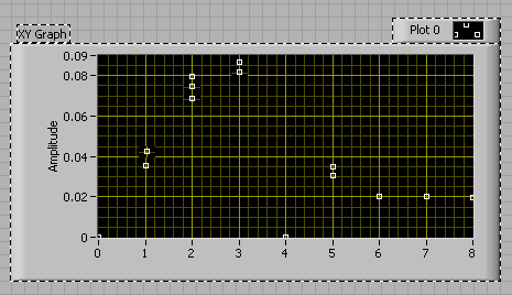
I have a table and a graph with a fixed axis x of Y values which varies. How to draw these new values y without replacing the previous ones? For example have a scatter of new data? Watch example Figure 1 below:
Figure 1: (Note: the image was photoshopped to demonstrate)
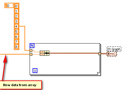
Figure 2: Current functional diagram, LabVIEW VI:
Thank you!
Just build up a simple concession:
-
I do not understand the difference between the two units (1px = 1 point). When you make a new document, why is - that someone would use pixels, and why is - that someone would use points?
Thank you!
A point is a unit of measure. It converts to 1/72nd of an inch.
A pixel is a measure. There is nothing else but a specification of color in a raster image. If pixel is not 'measured '; they are simply counted. A pixel can be any size. You don't know anything about the size of a pixel until you factor against a real measure of scale it. That's why raster 'resolution' is expressed in terms of PPI (Pixels Per Inch). Without the 'thumb', you can only count pixels; You can't measure them.
It's leaders in a program of raster image actually "count pixels." The leaders of the Illustrator are not. The only time where an officer "Pixel" in Illustrator is actually a pixel in a raster in Illustrator document image is when the raster image is adjusted to the 72 PPI and is placed to align with one of the sovereign increments. In other words, when the Illustrator leaders are set to 'Pixels', they are really just defined in Points (1/72 ").
Now, if you want to export the file to a raster format, and if you want to specify 72 DPI when you export, Yes, the "Pixels" sovereign will correspond to the pixels in the raster image exported. This correspondence object by object is only approximate, but, if you don't make sure that all of your objects are sized and placed in increments of any rule. Again, it is in every sense the same thing to have your rules defined in Points.
All measures in Illustator are actually expressed in points; the program converts to other units of measure. In order to present Points in its rules interface as if it were a unit of measure (which is not the case), Illustrator assume arbitrarily that the measure of a pixel is 1 point. Therefore, in Illustator, there is no functional difference between the Points and the "Pixels" in its leaders.
This silliness has led to much confusion. (And Illustrator is not the only program that does this).
Fear that you misread the Post 1:
function() {return A.apply (null, [this] .concat ($A (arguments)))}
1 inch in pixels depend on what you assign the ppi.
This comment does not refer to an adjustment to the level of artificial intelligence files. Parameter is not "PPI" in Illustrator that applies to the entire document, except for the setting of the resolution of the effects of pixelation, which acts on the PPI during which the pixelation effects are rendered. An Illustrator file does not have a specific PPI, because:
- This is the main purpose is to vector graphics, which, by definition, are independent of the resolution. Objects vector (paths of access and text objects) have no rasterization resolution.
- Illustrator is to assemble several objects. These include any combination of vector objects, text objects and raster objects. An Illustrator file can contain a number any object separate raster, and each of them can be adapted to any size. Real PPI to a raster in Illustrator object is therefore completely independent of the leaders page, even when they are placed in the unit fake "Pixels."
Defining the rules of "Pixels" is assumed more 'practical' or 'intuitive', when the project that you are working in is intended only for the pixelation screen (e.g.: web oriented work). But it is always false. It is quite different from the leaders of Pixel in a raster image program that has a resolution at the level of the document . For example:
1. in Photoshop, create a new image of 1 "x" 1 to 300 PPI.
2 show the rules with UOM set to po.
3. right-click the ruler and change UOM of Pixels. Note that the measure of 300 pixels is on the right edge of the image and is the same width on your screen, as was the 1 ".
4. image > ImageSize: disable resample. Change PPI to 100. Click OK.
5. notes that the measure of 300 pixels is always on the right edge of the image.
6. do a right-click the ruler and UOM change to inches. Note that the image is now 3 "wide.
Now compare this to what happens in Illustrator:
1 rectangle tool. Draw a rectangle 1. Align the upper left corner of the page.
2 object > rasterize. In the dialog box, enter 300 PPI.
3 show the rules with UOM set in. Note that the object measured 1 "width.
4 right-click the ruler and change UOM of 'Pixels '. Note that according to the leaders, the raster image 'measures' 72 pixels.
5 insertion of object > rasterize. Of the 100 PPI. Click OK. Note that his "measure", according to executives is still 72 pixels.
So, with the leaders of 'Pixels' the only time value Illustrator where to what it actually means anything in terms of actual pixels are when your raster images are set to 72 DPI or you want to export your graphic design at 72 DPI. In other words, it's the same as points.
JET
-
How to draw two points simultaneously on the image?
I want to draw two points at the same time on an image. I tried to use IMAQ point overlay and IMAQ meter for point. But when I try to plot two points using one of these two screws, I can't find a single point is plotted. How to solve this problem?
intensity wrote:
I want to draw two points at the same time on an image. I tried to use IMAQ point overlay and IMAQ meter for point. But when I try to plot two points using one of these two screws, I can't find a single point is plotted. How to solve this problem? If your image is zoomed out, the size can be to small to allow a good drawing of the point. Otherwise, IMAQ ecaple point works perfectly...
-
Plot data from several sources in table of graphs
Hello! I get 1250 pixel data and I want to plot the data for each pixel in a different chart. Each time, I get a data word and one word for the address of the pixel just, how do I trace these in an array of graphics? (Or the other table 1 d of 1250 graphics or table 2D 50 25 columns x lines).
When there was less that I used a case structure and graphics I would wire the address pixel in the selector of the case, now what can I do?
Any suggestions would be helpful, thanks.
Practically speaking it is not not possible to see 1250 chart 1 shot so its no need to have a lot of graphics. What we do in this situation is usually to initialize an array of elements of 1250 and replace these items when you receive data in a particular order. At the same time have a ring to control and update the name of items in the same order as you update the table. Now pass the array of values in the index table and connect control of the ring to the terminal index and connect the output to the curve. So when you select an item, you will be able to see the value of this element in particular.
-
Tracking of Multiple Point in Blackberry Maps
Hi all
I wonder if it is possible to use the webworks geolocation API to plot multiple points on a Blackberry or a Google map. Has anyone tried this yet? Are there references that you could give me to kick off development?
Thank you!
Yes it is possible. You ask just the API to update location and add the coordinate on the map. Just be careful with Google maps, as it can break WebWorks events.
-
Hello
Anyone know how to plot multiple points on a map? I think it's something to do with the blackberry.invoke.MapsArguments (locationDocument: Document) but I don't know how to use it. I tried:
var document = "
I can trace a single point with:
var args = new blackberry.invoke.MapsArguments(43.26, -80.30);
blackberry.invoke.invoke(blackberry.invoke.APP_MAPS, args);
Kind regards
I messed around with different XML structures and got it working:
var xmlString = '
Don't forget: You must multiply the coords per 100,000 (54.97781, so -1.61396 is actually 5497781,-161396).
More information on the elements XML here: http://docs.blackberry.com/en/developers/deliverables/11944/XML_element_location_893142_11.jsp and http://docs.blackberry.com/en/developers/deliverables/11944/XML_element_lbs_893141_11.jsp
Thank you for pointing me in the right direction, Tim!
-
The tolerance setting works for the "Convert anchor point tool"? Are there other ways?
Hello
I wonder if the setting "tolerance"in the preferences only works for the arrow tools?» I put it to 8 pixels and it seems OK for these tools, but when I use the tool 'Convert Anchor' point it is incredible difficult to hit a point for me. It seems that I have to hit a point exactly one pixel, which is hard with a screen high resolution.
My PC keeps beeping all the time and I'm getting crazy on this subject...
It seems that the framework of tolerance doesn't work here, I'm right? There are other parameters that could help me to work with this tool?Sorry if this is the kind of a beginner question, I have much experience with PS and LR, but not so much with Illustrator (and I couldn't find anything useful in the internet).
Thank you
RaschkoI agree, it is sometimes difficult to click on the sweet spot. Here are 3 proposals:
- Pay attention to the cursor icon. This will change when you are on a point anchor or direction.
- Try to turn on 'bearings commented. They can be a nuisance, but they are sometimes useful.
- Use the button "convert" on the Options bar. They may take a little longer but they are full-proof, moreover, you can convert or remove several selected points simultaneously using this method.

-
Handwritten scanned to Tiff - DPI/pixel size requirements for printing
Namaste"
I am planning to have a book printed sayings my teacher in his own handwriting in his journal.
The lyrics were written in ballpoint pen and twenty years old.
We their digitized by a scanner at hand gray in 300 dpi.
Since I cleaned up and cropped, so the standard 300 dpi is no longer there.
Because they are old, made with pen to ball and not very thick, it is not realistic to take 'out' of their context, so they're on a white background.
When I watch the news, scans, it says 400 points per inch (writing and white background), but when I look at what the pixel dimensions say, they are all less than 1 MB, mostly in the 300 k of Lombardo.
I don't understand this.
I was told that smaller 240dpi.
What is the relationship between the dimension in pixels and dpi? And how do you know that's enough?
Can anyone help clear this up for me?
When I take to the local printer and run them on their computer, for the test, the images seem fine.
I use PSCS3.
Thank you.
A girl-
When I scan art of the linework such as signatures, handwriting, drawings to the pen, etc, I updated the scanner for 2400 PPI print size, mode 1-bit/lineart/monochrome/NB (your scanning software should call one of them, the important bit is that it is NOT grayscale).
The reason for this was released most imagesetters and chemistries 2400 or 2540 DPI, scanning so at or near the resolution output provides the best appearance. If you are out on a laser printer or other office device you can scan its output resolution, 600 for example, but a file of 2400 PPi 1 - bit is not big at all then why not 'future proof' your scans so if you get them professionally out later they are at maximum quality.
Using a 1 - bit file removes all softened that you would with a grayscale image, and 1 bits can be easily made to have a transparent background so that you place them in a layout are a piece of cake.
My best advice for you is to determine your output size, then re-scan to 2400 DPI to the appropriate size.
For your other question, pixel dimensions is the number of pixels in the image and is the only true measure of the resolution of a digital image. Until that you determine the size of print DPI (pixels per inch) is not relevant, and the PPI will change according to the size of output: If you have a picture of 2000 pixels wide and you print 10 inches so your PPI is 200 (2000 / 10). If you export to 5 inches, the PPI is 400 (2000 / 5).
DPI (dots per inch) refers to the resolution of an output device. Both are commonly used to mean the same thing, but they are not synonymous - digital images contain only pixels, never points and output printers with points, never of pixels.
-
Move a selection one specific point distance
I need to move the areas of an image that I've selected using the unit of points.
For example, I get corrections in our copy where I need to replace some parts of image 8 points or more than 3 points.
Is it possible to do this easily? I can use the measurement for the distance measurement tool, but then it disappears when I'm actually trying to move the selection. The same thing happens when I try to use guides to the area. I wish I could put Photoshop to 'push' in the points instead of pixels.
Is it possible to make this easier?
(Photoshop CS4 version 11)
same diff just use Edit-> free transform instead
-
Problem graphic refresh with multiple locations
Scenario:
Draw two waveforms periodically to a chart (FMEM table for each iteration). Use the scope mode or scanning. Band mode seems to work a little better.Questions:
* If a plot in a wfm-array is empty for an update, another plot will not redraw properly. It will redraw when the second parcel was given, but the first plot will be badly drawn parts data points will be absent.* Scan mode leave many red lines and erase some data that's in the way.
Please take a look at the VI attached to see the (dare I call it bug) in action. If you have any ideas, please share.
I managed to find a partial solution to this problem, but the behavior seems weird and bug - like sweep mode always looks very bad.
Background:
I wanted to use graphics to create the best way to display the data, since I need to display several plots with high frequencies was updated, but the variable sampling rates. Before tracing data, it is already decimated so I only to draw as many points as I have available pixels.Solutions of circumvention attempts:
* ForceRedraw: Do nothing. I use it wrong?* Reporter FP: Does nothing.
To remove the empty FMEM at the end of the array of wfm (for an update/iteration):
-draws first properly draw
-don't pull on the second plot line
-If the window is resized, the data is deleted, only the last part of the plot is visible. Looks like previous plot data are "forgotten".
-Automatic scale will not work. It will be autoscales on the final section of data.* Increase the length of history: does nothing.
* Put a flag in front of the chart: live to be redraw until the window is resized. Update graph becomes very slow. The X-scale will go berserk. I used that thing once on an indicator of flickering text and placed an invisible object in front of it, which has contributed to this situation.
* Resize the window: works! Not a very practical solution. Scan even seems ok.
* Use XY-graph: my goal was to make the most efficient way to display data with relatively high update rates. I used a XY, but when I got a little bit of these graphs, the cpu load was very high and I checked it was the actual writing to the graphical indicator that took all the cpu. I tried the update less often and I already decimated data before sending it to the curve, but the cpu was still too high. Replace with the graphic work like a miracle with almost no cpu load
* If a wfm is empty for an iteration, draw the last trace point once again, but with a very small time-offset positive (I think it didn't work well plot with new): graph redraws ok in reach mode but not in scan mode. But if I draw again and again this last point, the other plot will finally cause the x-scale to autoset and I will need to keep track of the scale and not re - plot this point only if it is out of scale-x. It starts to get difficult here and I have not solved all the problems that may arise here yet, but it is of the workaround I use now. And for the graphics, I did find a way to disable this automatic update of the scale (is there a way?).
I did and VI test to test these issues (attached), where the different workarounds may be tested by activating different buttons. Run it just in the default to run without active workarounds and it should show the issue of discounting very clearly. I tested it on 2 PC and LabVIEW 2013, 2012, 2010 and 8.6.
This has been touted as the CAR 455443.
Kind regards
Jeff Peacock
Product Support Engineer | LabVIEW R & D | National Instruments
-
Hello.
I spent the afternoon looking for a solution to my problem in this forum but I did not yet find.
I need to draw points to a picture on a picture 2D and until now, I tried with 'Trace XY VI', 'Attracting Point VI' and this one:
With the first VI I get lines instead of simple points. With the other, the drawn pixels are too small and I can barely see them. Even with the third argument.
Anyone know how to plot more big points?
Thanks in advance.
In the thread, you have access, CC suggested using the oval Overlay IMAQ VI to draw larger circles to these points. Have you tried that?
Also, should you use IMAQ or you can use the image control screws?

Maybe you are looking for
-
HP pavilion g6 2241 his: power of hp pavilion g6 241sa failure
Hello forum members my query is, my problem was, Ive had several spills coffee light on my hp Pavilion 2241sa g6, al ive cleaned, new keyboards restarts etc, then for 3 months, he just put on the table with the battery, because the last attempt of cl
-
Upgrade the processors HP G62-228NR
Hi, I have a HP G62-228NR , and I am wanting to upgrade the Phenom II processor here. I want to just make sure that this IS compatible, im sure it is, but I'd like a second opinion, thanks for any help!
-
migrate from vista to mac parallels, need a new key
Phone number of Windows Vista from Microsoft Italy HelloHelp, please. I need phone number for Microsoft Italy Windows Vista, or any other phone number get a new key for this program.I migrate this Windows Vista for my MAC Parallels and has my old PC.
-
using the group name and password group in client anyconnect
Hello. Is it possible to use the group name/password of the legacy in customer cisco anyconnect vpn client? I checked the AnyConnect Administrator's Guide ' VPN XML Reference"and found nothing on this subject.
-
How to install win. 8 64 bits on my IBM Thinkpad T40 32-bit
How to install win. 8 64-bit ISO on my IBM T 40 Thinkpad 32 bit dvd Moved from the installation of XP, set at level and activate Forum.