Polar data in a graph of intensity
Hello, I'm trying to plot a graph of the intensity in a real-time application. The problem here is that I get to control the scale, the RADIUS and the angle separatedly, any ideas on how I can trace in a graph of intensity?
Hi MrX,
It is pretty basic math to convert r & theta x & y.
LabVIEW provide even basic functions to do this!
Tags: NI Software
Similar Questions
-
Link z scale graphical data without autoscale marker of intensity
When directly change us the value of marker without autoscale, no change can take place on the route of the graph of the intensity of. So, how can we link the values of the scale marker z for the data displayed on the ground?
To be more precise, because many people may prefer that they have the graph of the intensity for different sets of data with the same z scale so that they can very easily compare visually the value z-scale to compare the color. But for the different sets of data, they can get different and AutoScale will result in trouble for the same z scale.
However, when deactivate us autoscale and just do the scale marker z the same, in fact the graph will be is more really connected with the plot and making it impossible to compare the values of z of the plot.
I tried to change the beach instead of the brand, but it does not work for scale z that when we get a negative value for the location of marker z scale, the graph only get something very weird as only black and white.
So, how can we define two graph of intensity at the same z scale and z scale and at the same time markers have the graph link to the data we have?
Hi weirpenguin,
Please see the new example. I changed it to LabVIEW 2009 and U8.
If the graphic is U8, it means that data cannot be outside the range of 0-255 anyway, right? U8 is only 0-255. Then why grow you to be larger than 0-255 range?
Kind regards
-
Can transport data in multiple graphs
Hey,.
Right now I'm working on a project of analogue data of feedback from sensors on a petblowing machine to a pc at the office.
So far, I can send messages with a different id... The messages of 4 part Arb ID, ID seen, length (Yes), value.
The intension is to separate data on different graphics. As ID 32 goes to figure 3 and 16 ID goes to figure 2. Now it's my problem.
The values are similar 0-255, and they must also be monitored. So I had 4 plots on a graph to change the color on the value.
But when I want to redirect messages to the different graphics that I receive all my data but the double. Or when I send the data to a chart the
another past and if I look at with my probe he values changing if nothing was happening. So far, it works when I show my
data on a graph and proceed with a deal that leaves an id to pass so that the graph can be drawn. Someone an idea how I can make it work with multiple
graphs?
If you want to take a look at the code all also.
Thanks in advance...
OK so I'm done today of the VI... Normally, everything should work as it should.
I want to thank demux for the great support and everybody to watch...
The final VI is attached...

-
Creating a graph of intensity from the discrete values
I have 4 discrete results. I want to display this information in a graph of intensity. I want each of these discrete values to have a specific color on the intensity. If possible the value 4: a = 1, b = 2, c = 3, d = 4. If I spend 2 x 2 table 1,2,3,4 in the graph of the intensity, I want a red, b blue, c green, d be and yellow. How can I specify that on the chart? Is there a good example?
Thank you!
In this thread, I give an example where you set Z scale by using a property node. In your case switch off interpolation of Z scale as well.
http://forums.NI.com/NI/board/message?board.ID=170&message.ID=437481#M437481
-
dispplaying data on the graph of waveform inside/outside while loop
I create a vi using the random number generator, entering the number in the function(express>>arithmateic>>maths>>trig>>sine) fishing and connect the output of the function sine waveforms. Table of waveform show no problem. If I replace the with graphic waveform table, I get an error that the source type is differenct type of sink. I then put waveform chart outside loop everything hoping that tunnel would act as a table, but still I get the same error. I then put build table palette between all border and loop waveform graph which is placed outside the while loop. I get no error, but no data is displayed on the graph of a waveform. Theoretically, if I press stop I would see a distorted sine wave on the waveform graph, but this doesn't seem to be the case. I am wondering how to view data on the graph of a waveform in such cases!
Thank you in advance for reading and help!
See you soon
First of all, you can take a part of the basis of LabVIEW tutorials.
Since you need to work with a chart and it is the preferred method to display data point by point, I don't know why you try to use a chart. In any case, you cannot use all simply a table of generation because that would be just the result of the last iteration and your graph indicates it is a single point. If you activate autoindexing, then you get all the values, but not before the end of the loop. If you were to use a shift register and the build dashboard, you might place the graphic inside the loop, but then you would face performance issues that the table would grow uncontrollably.
-
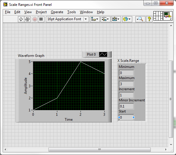
How to read the values of the scale of a graph of intensity?
My goal is to read the scale varies (SHOWN Max and min values) of a graph of intensity.
I want to do a scan of a box, graphically display the result in the graph, zoom in on something interesting, and then use the zoom coordinates to define the area for the next analysis.
Is this possible and how?
If not possible, is there a work around?
Use the nodes property 'XScale.Range' and 'YScale.Range '.
-
Table 4 x 4 in a graph of intensity
Hi, I was wondering if anyone is able to help me? I am doing a 4 x 4 table in a graph of intensity, but at the moment, I can't get a 2 x 8! It's probably something very simple - I have attached the code and a screen shot of this message. Someone at - it ideas? !!! Thank you.
Hi altenbach. Tried your suggestion and it worked immediately! You are a lifesaver! See you soon!
-
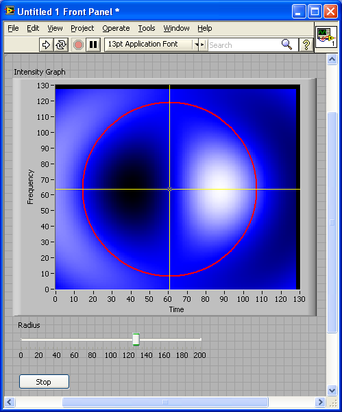
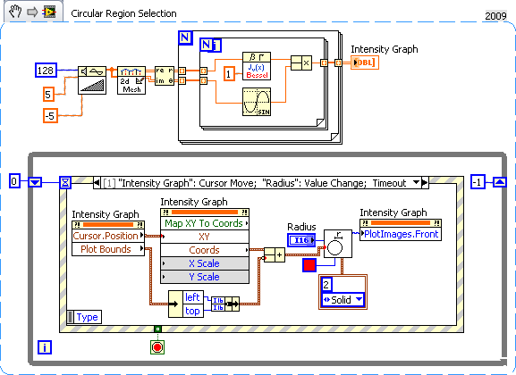
Refining circular cropping a graph of intensity
I am trying to create a more efficient and friendly programmer to circular harvest a graph of intensity. Currently I can crop the graphic with a matlab script but try to improve the process. I would like to be able to say where the image will be cropped before executing the command. My solution was to place an invisible plot with the same scale above the graph which can draw a circle around the area to crop. As you can imagine, aligning these graphs is boring and does not lend to rearraging my vi. I'm looking for a better way to draw a circle/say where it is harvested beforehand.
This is a relatively simple method by using the PlotImage property and a slider.
-
Recovery/annotation of text on a graph of intensity
Hello
I'm trying to overlay a text on a graph of intensity. It would be good if the text overlay behaved like an extra layer, like the IMAQ image to display indicators.
I tried 2 methods.
1. I'm creating a text overlay, and I am placing it on an image control. The image control is placed on the graph of the intensity with transparent borders (pretend that there is not).
The problem with this method is the background of the text overlay is not see through. The other problem is I can not pan and zoom in/out with the tools of graphic intensity given that the image control is located at the top of the graph of the intensity.
Later, I can see questions trying to pan as the overlay should follow the pan movement.
2. I'm creating a text overlay by using the image control and its conversion into a graph of intensity (convert picture to pixmap etc...). This second intensity graph contains only the text overlay. Then I'm merging the two graphs of intensity by pulling on some 2d on a main intensity graph subsets to the place corresponding to the mouse pointer, replacing it with the second graph of the intensity (the one containing the text overlay) and put it back in its original spot in the 2d array.
It's slow thing (700ms for a text overlay) and the question is now the overlay is merged with the graph of the intensity, it changes color when you play with the Z scale palette and grows with the zoom.Any suggestions?
Thank youUse the property of field intensity, draw images-> before. It's actually a superposition of control photo directly on the chart (free). I like the images in the field who have been snuck in the graphics, there are a few versions a feature very underused. Now just use all the photo functions to create taxt or that you could want.
-
How to clear data from XY graph for another try
I have a chart XY Motors charges against intensity. I used shift registers to build the table VI. After termination of the program once using terminal stop. And I deleted the graph. When I started taking the measure a second time, same data again before the first. So how can erase it. Please answer
It's a very quick way to do it: initialize your shift registers.
What happens in your VI is that, after the VI stops (when you click the stop button) the data contained in the shift registers (your matrices X and Y) remains in memory, if you rerun the VI it will add data in these tables.
To initialize your shift, registers, you need to connect vacuum table them before the while loop. Like this:
hope this helps
-
Type of input data for the graph waveform
Waveform graphs do not change the type of input data according to the wire. When I create a new chart that is set to double data type and does not change what I connect to waveform, so I copy graphics to another VI for appropriate indication. But the graphics don't accept complex data. How can I change the type of input data?
The graphics in vi you have posted behave properly on my machine.
Change according to the type of data that connect you to them.
Maybe something wrong with your installation?
-
Placing several sets of data on a graph (LabVIEW for Excel)
I read in a 2D array (first rank values of the x axis, 2 values for the value axis in line, 30 columns) of a number of excel files. With each iteration of my loop for example, I read in 1 all of these 2D table data, and I'm tracing the curve (using Excel Insert graphic) before I close this file and move to the following.
I want, however, must be able to generate 1 chart at the end with all sets of data together. So far, whenever I'm iterating, new data erased the old, and in the end I only get 1 set of data (the last game) on the 1 graph.
I searched through the Forum similar topics, but 1) I have all my data read or typed into a nice big table, they come in the iterations instead, 2) my data values do not share the same values for the x axis, while the beach is almost the same (from 0 to 1) and the number of data points is always 30 (3) I don't think I can use shift registers because all my data is obtained in my loop, when I open Excel (also in the loop) files and read them, so I did not 'Original data' to initialize the shift register.
Any suggestions on how I was able to read the data, graphics, read the new data, then graph on the same graph without losing my old data?
Thank you!!
Kalyie,
You may need to force your data to have the same category axis.
Another option would be to insert data in excel instead of a graph. From within excel you could have a set graph in place who knows where the X values and are there for each data set and it will draw it automatically.
You can also try messing around with the Graph.vi of update to Excel.
I had limited success with the Excel update Graph.vi, but worth a visit.
Thank you
Joel C
National Instruments
-
Zoom to part of a graph of intensity?
I have a graph of the intensity at which the axis represents discrete channels. I want to be able to zoom the picture so that there are a whole number of displayed channels. The default behavior seems to be that when you the xoom, it is possible to see half the field strings. What I have is a situation where if the zoom on the y-axis range showed channel e.g. channel 28.1 to 22.7, that intrigue resize the y-axis of the range of 23 to 28. I would also like to ensure that a minimum of one channel displayed. I see no obvious and easy way to do it, but I would be wrong...
Thanks for any help,
Joe
You mention the intensity graph and table either. Because they are quite different, can you clarify what you actually?
Personally, I would use all digital controls to define the xmin, xmax. You can do the math and will check if necessary.
Alternatively, it is also an event "Scale range change", that you can use to change the beaches after the user has zoomed in.
-
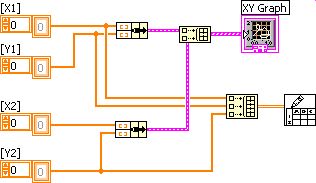
How can I write the data on the graph xy
I want to write the values of x and y... how can do that... I tried with the independent cluster.but the sons weren't told connected.it that the dimensions are not same.why my watch 3 xy dimenssional table? He must have a 2d painting.
can someone help me please...

Ignatius
Normal, 'Write on worksheet File.vi' required a simple table 1 d or 2D as input and not a specific type in the cluster (because the XY graph is a cluster).
So, given that your [X] data is the same for every [Y], you could build a 2D data table to use (by implementing the 'build picture' with [X] & [Y]).
If it is not the case (same [X] for all [Y]), you will have to proceed to another method-online 2 files or the conversion of custom text before writing.
-
Question on how to data field/table/graph xy
Hello-
I currently have a VI which reads in information through the DAQ Assistant, in two tables of waveform (load / time) and the displacement / time. I would like to be able to take this information and draw another (load vs displacement). I have converted the sets of dynamic data from the charts of waveform in both ways (load and displacement) and then them grouped in an array of clusters. I tried adding a waveform chart in the table of cluster, however it does not seem to be traced. (It is located in a loop so that it must constantly be updated because the control is underway.)
I would appeciate any help you may have. Please let me know if you have any questions.
Thank you for your time.
A graph is just simply not true, if you want to draw one table against another. This is what a XY chart is for. Just take your existing arrays and group them together. If you turn on the context-sensitive help (and it really takes on all the time) on the block diagram and move your mouse over the graph, it shows you exactly how to wire the data. Given a graph is a no story, you will need to implement if necessary. There is a graphic called example XY or just look for the Board of Directors. Many examples that use a couple of shift registers. The graph XY Express can be used as well.
Don't know why you want in a separate loop. Place it next to your written chart would make as much sense.
Maybe you are looking for
-
For example, when I enter the search term "cabinets" and get a page/tab search results with suggestions such as Sears, JCPenney, or Amazon, I want to be able to click on Sears and open the Sears page in a new tab/page. I want to be able to close the
-
Hello I can't find the switch cuda in my PowerMac g4 dual mirrored, 1.00 What is the difference between reset pram by touch or cuda? Switching on the open Mac I can see a small red light and I listen to the classic sound but nothing on the monitor. F
-
driver for SM bus and need another controller
Hello I have a HP 15-N241CA just did a clean install of Windows 7 Ultimate X 64 now my device manager tells me that I have no drivers for: SM Bus controller PCI\VEN_1022 & DEV_780B & SUBSYS_216F103C & REV_3APCI\VEN_1022 & DEV_780B & SUBSYS_216F103CPC
-
How can I turn the LCD on my A1300?
I haven't used the A1300 enough to remember how to use it. I just tried to take a picture using the LCD screen and I see is the info from the camera. I used the viewfinder, pulled a photo, and I see that when I press the button to the left of the "Me
-
What ink is the HP Pro 8500 JO is for? Basis of dye or base Pigment, all 4 colors or a mixture?