power density spectrum
I'm using strain gage accelerometers to collect data from acceleration axis X, Y and Z on channels separated as a way to quantify the vibrations in the cabin of an off-road vehicle. Using the DASYLab "formula module" I put across the output of the accelerometers to read directly in gs, or 32 ft/s/s = 1 g.
If I use the DASYLab 'fft module' to provide a spectrum of power for a waveform g time density vs generated by one of my accelerometers, what are the scale units which are delivered by the "Y/t diagram module? I know that the x in the table scale units are Hz.
I am producing a figure of displaying data that has the same format as power spectral density data presented in the figures in Mil - Std - 810 G method 514,6 Annex C. This paper presents data from sprectral in the form of curves of (g ^ 2) frequency vs /Hz.
So far, none of the data I gathered in my vehicle, looks something like the data presented in the in the mil specs.
Thank you for reading the question, I asked, given it and answer this question instead of going some other marginally related topic. I sincerely appreciate your knowledge and your willingness to share.
Tags: NI Products
Similar Questions
-
Weighting of exponential power FFT spectrum mode
In the spectrum power of FFT VI mode exponential weighting from the link:
Weighting is applied according to the following equation.
where Xi is the result of the analysis conducted on the ith block, Yi is the result of the average of X 1 XI, N = i for the linear weighting, and N is a constant for the exponential weighting (N = 1 to i = 1).
For the exponential weighting, N is a constant. What is its value?
Yes, but N = I do not mean that it is constant. For weighted linear N = i means N = 1 when I = 1, N = 2 when I = 2... And on average stops when I reached your set number.
For the exponential weighting N is constant (the number that you define) that leads to an exponential weighting. The average never stops in this case.
-
Coercian dot on the power spectrum
Hi all
Was just curious to know why I have a point constraint on my FFT power spectrum when it fed a waveform? I thought (and detailed help is agree with me) that a waveform has been the type of entry required. There may be more going on here that I realize, but clearly I'm not.
As a sidenote, I'll you this because I replace an express VI in an application, that they gave me to end up and the express power VI spectrum seems to give results that are disabled by the square of the input function. OK then that sentence makes little sense, what I mean is when I plug a function up to my DAQ board generator and supply a sine to a known frequency spectrum of power express VI sets out 16 Hz instead of 4 Hz, 2500 instead of 50. The spectrum of normal power VI works fine. Do not Express VI anyway but just curious.
Thanks in advance!
Is the matrix Y DBL? SGL or EXT would produce a dowry of coercion.
Lynn
-
RFmx and FetchSpectrum using Python
Hello
I'm trying to use RFmx through Python.NET. The code works until I have try to catch the spectrum using FetchSpectrum():
# create the name of the variable before you pass it to the method .NET
spectrum = RFmxSpecAnMXSpectrum# This does not work!
specAn.Spectrum.Results.FetchSpectrum (", timeout, spectrum)Here's the complete code:
import clr
import sys# location of the assemblies
assy_path = r'C:\Program files (x 86) \National Instruments\MeasurementStudioVS2010\DotNET\Assemblies\Current'
sys. Path.Append (assy_path)CLR. AddReference ("NationalInstruments.RFmx.SpecAnMX.Fx40")
CLR. AddReference ("NationalInstruments.RFmx.InstrMX.Fx40")from NationalInstruments import *.
from NationalInstruments.RFmx.InstrMX import *.
from NationalInstruments.RFmx.SpecAnMX import *.# The VSA settings
resourceName = "5606_slave."
centerFrequency = 10.0e9 # Hz
referenceLevel = - 10 # dBm
externalAttenuation = 0.00 # dB
Timeout = 10 seconds #.
span = 1.0e + 6 # Hz
RBW = 100e3
averagingCount = 10instrSession = RFmxInstrMX(resourceName, '')
# configuration VSA
rbwAuto = RFmxSpecAnMXSpectrumRbwAutoBandwidth.True
rbwFilterType = RFmxSpecAnMXSpectrumRbwFilterType.Gaussian
averagingEnabled = RFmxSpecAnMXSpectrumAveragingEnabled.False
averagingType = RFmxSpecAnMXSpectrumAveragingType.Rms
#specAn = instrSession.GetSpecAnSignalConfiguration ();
specAn = RFmxSpecAnMXExtension.GetSpecAnSignalConfiguration (instrSession)
specAn.ConfigureRF('',centerFrequency,referenceLevel,externalAttenuation)
specAn.Spectrum.Configuration.ConfigureSpan('', span)
specAn.Spectrum.Configuration.ConfigureRbwFilter (", rbwAuto, rbw, rbwFilterType)
specAn.Spectrum.Configuration.ConfigureAveraging (", averagingEnabled, averagingCount, averagingType)
specAn.SelectMeasurements (", RFmxSpecAnMXMeasurementTypes.Spectrum, bool ())
specAn.Commit ("")# run acquisition
specAn.Initiate('','')# find the peak power in the spectrum
_, pkAmp, pkFreq, freqRes = specAn.Spectrum.Results.FetchMeasurement (", timeout, float (), float (), float ())
Print "peak power: dBm {:0.2f} to {:0.6f} GHz'.format(pkAmp,pkFreq*1e-9)}}""""
A .NET method may require user pass the variable name that it wishes to
change as an argument. Python is not compatible "pass by reference", but the
the variable name must exist in python, before he can be handed over to the .NET method.
The .NET method will simply point to the new instance.http://nbviewer.IPython.org/GitHub/jonnojohnson/Agilent/BLOB/master/Python_Automation/Python_Automation.ipynb
"""# create the name of the variable before you pass it to the method .NET
spectrum = RFmxSpecAnMXSpectrum# This does not work!
specAn.Spectrum.Results.FetchSpectrum (", timeout, spectrum)instrSession.Close)
Here is the error:
Traceback (most recent call changed):
File "
", line 3, in
specAn.Spectrum.Results.FetchSpectrum ("", timeout, spectrum)ArgumentException: Object of type 'System.RuntimeType' cannot be converted to type ' NationalInstruments.Spectrum'1 [System.Single] & ".
at System.RuntimeType.TryChangeType (Object value, Binder binder, CultureInfo culture, Boolean needsSpecialCast)
at System.Reflection.MethodBase.CheckArguments (Object [] parameters, Binder binder, BindingFlags invokeAttr, CultureInfo culture, sig Signature)
at System.Reflection.RuntimeMethodInfo.InvokeArgumentsCheck (Object obj, BindingFlags invokeAttr, Binder binder, Object [] parameters, CultureInfo culture)
at System.Reflection.RuntimeMethodInfo.Invoke (Object obj, BindingFlags invokeAttr, Binder binder, Object [] parameters, CultureInfo culture)
to Python.Runtime.MethodBinder.Invoke (inst IntPtr, IntPtr args, kw, MethodBase info, methodinfo MethodInfo [] IntPtr)Any ideas?
Ah! That's about all. Here's what worked:
spectrum = NationalInstruments.Spectrum [System.Single] (0)

_, spectrum is specAn.Spectrum.Results.FetchSpectrum('',timeout,spectrum)
Here is the result and the final code for future reference:
import clr

import sys

Import os

import matplotlib.pyplot as plt
Import numpy as np# To Program Files Windows environment variable
Program_Files = os.environ ['ProgramFiles (x 86) ""]
assy_path = os.path.join (program_files,
"National Instruments",.
"MeasurementStudioVS2010,"
"DotNET"
"Assemblies."
'Current')sys. Path.Append (assy_path)
CLR. AddReference ("NationalInstruments.Common")
CLR. AddReference ("NationalInstruments.RFmx.SpecAnMX.Fx40")
CLR. AddReference ("NationalInstruments.RFmx.InstrMX.Fx40")from NationalInstruments.RFmx.InstrMX import *.
from NationalInstruments.RFmx.SpecAnMX import *.
import NationalInstruments
Import System# The VSA settings
resourceName = "5606_slave."
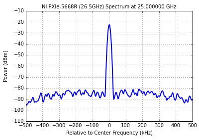
centerFrequency = 25.0e9 # Hz
referenceLevel = #-10 dBm
externalAttenuation = # 0.00 dB
Timeout = 10 # seconds
span = 1.0e + 6 # Hz
RBW = 100e3 # Hz
averagingCount = 10instrSession = RFmxInstrMX(resourceName, '')
# Get the model number
_, Model = instrSession.GetInstrumentModel (", Str())# configuration VSA
rbwAuto = RFmxSpecAnMXSpectrumRbwAutoBandwidth.True
rbwFilterType = RFmxSpecAnMXSpectrumRbwFilterType.Gaussian
averagingEnabled = RFmxSpecAnMXSpectrumAveragingEnabled.False
averagingType = RFmxSpecAnMXSpectrumAveragingType.Rms
specAn = RFmxSpecAnMXExtension.GetSpecAnSignalConfiguration (instrSession)
specAn.ConfigureRF('',centerFrequency,referenceLevel,externalAttenuation)
specAn.Spectrum.Configuration.ConfigureSpan('', span)
specAn.Spectrum.Configuration.ConfigureRbwFilter (", rbwAuto, rbw, rbwFilterType)
specAn.Spectrum.Configuration.ConfigureAveraging (", averagingEnabled, averagingCount, averagingType)
specAn.SelectMeasurements (", RFmxSpecAnMXMeasurementTypes.Spectrum, bool ())
specAn.Commit ("")# run acquisition
specAn.Initiate('','')# get x data
spectrum = NationalInstruments.Spectrum [System.Single] (0)
_, spectrum is specAn.Spectrum.Results.FetchSpectrum('',timeout,spectrum)# get data
analogwaveform = NationalInstruments.AnalogWaveform [System.Single] (0)
_, analogwaveform is specAn.Spectrum.Results.FetchPowerTrace('',timeout,analogwaveform)close a session #.
instrSession.Close)# calculate the frequency and power
startFrequency = spectrum. StartFrequency
frequencyIncrement = spectrum. FrequencyIncrement
sampleCount = spectrum. SampleCount
stopFrequency = startFrequency + frequencyIncrement *(sampleCount+1)
freqArray = np.linspace (startFrequency, stopFrequency, sampleCount)
current = list (analogwaveform. GetRawData())results of tracking #.
XScale = 1e-3
PLT. Plot ((freqArray-centerFrequency) * XScale, Power, LineWidth = 2.0)
#plt.ylim(referenceLevel-100.,referenceLevel)
PLT.yticks (NP.linspace(referenceLevel-100.,referenceLevel,11))
PLT.xticks(NP.linspace(-span,span,11)/2*XScale)
PLT. XLIM(-span/2*XScale,span/2*XScale)
PLT. Grid (true)
PLT.xlabel (' from center frequency (kHz) ")
PLT.ylabel ('Power (dBm) ")
PLT.title ("{} {:0.6f} GHz spectrum".format(model,centerFrequency*1e-9), fontsize = 'medium')
PLT. Show() -
DSA 4461 FFT on both channels simultaneously
Hello. I use card PCI 4461 DSA and am currently power density measures (FFT) on both channels simultaneously.
I found the example of the case acoustic and vibrations, but it is only for a single channel.
How can I do to measure 2 channels? I have to add a channel more 'DAQ - mx create a channel' vi series?
I don't know how vi DAQmx REad it would handle. I have had 2 channels for voltage using Express VI.
Thanks to Labview 8.2
Thank you
I advise to use extensions on your DAQmx task to select multiple channels. When you select the physical channel, choose Browse and a list of all available channels will be filled. Hold CTRL and click on different channels to add to your task. See the attached pictures if you have any questions on how to do it.
You can choose to display these data on a single waveform chart, or you can split the signal and analyze each channel separately. Try this and see if it works for you.
-
Hello
I would like to compare the values of one signal (table 1 d) with each other and then displays the maximum value. But only if desired.
It should be in principle, a peak hold function, I always displays the maximum value.
In the "power FFT Spectrum.vi", there is such a "ridges". However, I don't know how I can integrate it without the "FFT Power Spectrum.vi' in my vi.
Maybe someone can help me here.A picture of the vi says maybe more (the picture shows a first attempt, which unfortunately does not work as expected).
Thank you and best regards
Alesis
All you need is a little help from Max & Min function (at least for the way I remember Max Hold)
-
Hi, I need, and I don't know if it's possible, to convert an indication in dbm are supplied with a field meter volts/meter for elettrosmog control tv, can anyone help me? Thank you
Hello!!
dBm and adimensionnel unit used in measures of power--> 1dbm = 10 log [power (mW) / 1 (mW)]
While
Volts/m is a dimensional unit used in the measurements of the electric field.
In order to connect, you need to know the impedance characteristic of the medium of propagation and expansion of the surface.
Pretend to work in a vacuum at a typical distance r = 1 m from the source, you get:
ZC = 377 ohms
S = 4/3 pi r ^ 2 = 1, 04 m ^ 3
so, you can calculate the absolute power:
P (Watt) = 1/1000 * 10 ^ [dBm/10]
and the standard power density:
P/m ^ 2 = P (watts) / s = P (watts) / 1.04
which is equal to:
P/m ^ 2 = V/m A / m
You know that:
A / m = V/m 1/Zc
so:
P/m ^ 2 = (V/m) ^ 2 * 1/Zc
and you have:
Volt/meter = [(P/m ^ 2) (* Zc)] ^ (1/2)
Have a great day!
-
Hello
I have problem with my program.
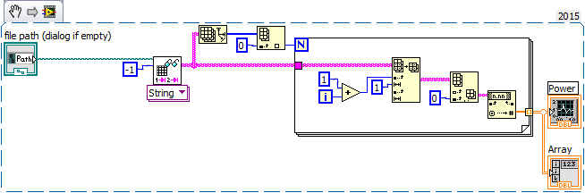
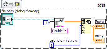
I can't create a graph of my table...First of all, I read valuse of my file that looks like:
Power   Density Power   Frequency   Voltage Current
25,334650E-6    36,900306E-6    190,825684E+0   862,942045E-9   864,983974E-9
24,206653E-6    35,157042E-6    190,825684E+0   827,446001E-9   882,577353E-9
25,580297E-6    36,612237E-6    190,825684E+0   851,907600E-9   863,375192E-9
25,898957E-6    36,910784E-6    190,825684E+0   824,207802E-9   829,508508E-9
26,401393E-6    34,364417E-6    190,825684E+0   807,872595E-9   821,918377E-9
25,830897E-6    34,823581E-6    190,825684E+0   813,358895E-9   836,582956E-9
24,849543E-6    35,491383E-6    197,160889E+0   813,544546E-9   880,989262E-9
25,744268E-6    34,769462E-6    197,160889E+0   826,847838E-9   837,655477E-9
Then, I want to create a chart of the first column. But it did not work...
What can I change in my program to solve my problem?
Concerning
Hi piotrek,.
Why do you read 'String' when you need numbers for a graph?
And what's the problem using only not Autocleanup before posting your diagram?
It could be as beautiful as that:
Your VI tells us: you need learn the AutoIndexing with loops, using effective functions (such as "+ 1") and read the LabVIEW help on each function.
After reading the help of LabVIEW yu could simplify your VI to this:
-
The power spectral density function counts inaccurate amplitude caused by the window function?
I'm new to this forum, so please let me know if this would correspond better to a different discussion forum.
Here's the question:
I would like to know if the power spectral density function ("FFT PSD for 1 Channel.vi") automatically compensates for the loss of the amplitude of entry caused by the window function. In other words, is a specific window correction factor applied within the PSD vi or do I apply manually?
Details of the background:
I tried to answer the question myself by generating a sine wave sampling, it as it is periodic in record time (i.e. 0 to each end of recording time). The frequency of the sine wave was such that the frequency would exactly correspond to a spectral line in the PSD. Then I generated the PSD of the sine wave twice: once using a Hanning window and once using a rectangular window (not on average in both cases). The rectangular extent of the PSD with windows to the frequency of the sine wave is 1.5 times the size of the PSD with a Hanning window applied.
The experience above indicated to me that a manual setting of the PSD output for the function of window was necessary, however, I repeated the above experiment using random vibration data and does not clear 1.5 x factor. I have also been informed by his colleagues that the PSD should set for the window function.
Thank you for your comments.
Spectral leakage. When you use a finished sample data from the spectrum resulting is the convolution of the spectrum of the signal as if it extended indefinitely in time with the spectrum of the window. Even if you do not use a window function, you actually have a rectangular window the same width as the sample size.
Draw out of the VI PSD with all style of trace to show points to the data points. Turn off Auto scale on the X axis, and expand the graph around your pic. Look at the results of different windows. In any case, there are several values non-null. With actual sampled data of limited duration, you will never get the idealized line spectrum.
If summarize you the output spectral value remains close to 3.2 for all windows.
Lynn
-
Amplitude of power spectral density is about 1e6 times higher than it should be
Hello
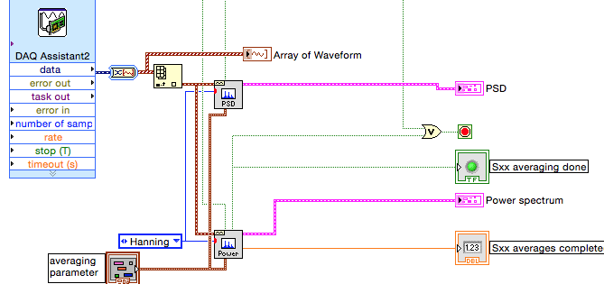
I use vi of power spectral density (PSD) and power spectrum vi in the process the same time acquired by data acquisition (attached figure) signal. I sent in a 0.1V sinusoidal signal of 1 kHz in data acquisition, and the power spectrum gives me the right power RMS at 1 kHz (which is 0.05), but DSP vi gives me 1670, which isn't fair. The amplitude THAT PSD gives me must be smaller that the power of amplitude spectrum gives me. This is supposed to be a simple treatment, but it drives me crazy. Is someone can you please help me solve this problem?
Thank you very much.
INSA
If you convert the dynamic data Type (badly) from the DAQ Assistant for an array of waveforms, sampling rate information must be included and none of your additional calculations is required because power Sprctrum and the PSD VIs will take care of this... This is what Dennis mentioned in his post.
We cannot do a lot without data. Please display waveform data type and add a waveform table indicator. Run the VI until the indicator data. Stop the VI. On the Edit menu, select use current default values. Save that VI, possible with a different name and post it. We will then have access to your data.
Lynn
-
My HP spectrum X 360 convertible is overheating with a high degree of loss of battery power. The system turns off often. Extreme overheating is a major concern for me. The rapid descent of battery greatly interfere with my work.
What should I do to get my system on track as before?
-
Spectrum for computer laptop 13-v051na: connect more capacity power adapter Message
After starting, I get the following message. "For maximum performance, connect a higher capacity Power Adapter.
The power adapter I use is provided in the box with the notebook. So I'm at a loss on what to do and do not understand the impact with an adapter in addition low capacity.
AFAIK, the ability for the laptop power adapters are not in the HP store.
Details of the laptop;
Spectrum of HP for computer laptop 13-v051na, part number; F6P95EA #ABU
(Note that this laptop is a variant of PCWorld/Dixons cell phone spectrum HP Ref. 13 - v001na F4W33EA #ABU)
Details of the charger supplied with the notebook; (markings on the charger)
Power supply for charger USB - C;
Model; TPN-CA02
HP part No.; 848067 002
HP Spare; 848293 850
Entry; AC 100-240V 1. 4A
Exit;
5V 2A DC
12V 3A
15V 3A
45W max
Additional information about the message;
Message; "For maximum performance, connect a higher capacity Power Adapter.
In the taskbar, the icon indicates that the message is from HP system information.
Application properties (found via the Task Manager) HP system information are;
- File; USBCMSG.exe
- Location; C:\Program Files (x 86) \HP\HP event system
- Version of the file; 1.4.14.0
- Version of the product; 1.4.14.0
- Date of change; 20/06/2016
- Original file name; SysInfo.exe
Good news is that there is a difficulty.
I was given further guidance to Support cat HP, including a link to the page software and downloads. This shows a new BIOS Softpaq, which has not been suggested by HP Support Assistant. Details of the update of the BIOS are;
HP Notebook System BIOS Update (Intel processors) F.26 Rev.A 15.4 MB 24 August 2016
File name: sp77130.exe
Communicate details
Exit the: 12 August 2016
Version F.26 Rev.AI have applied this update of the BIOS and the wrong power adapter warning message no longer appears.
Problem solved. Thank you HP.
-
'power' and 'size' in the power spectrum?
When I choose "power at the stage of the power spectrum, numbers in my data were negative. I don't understand why. What is the difference between "power" and "ten factor"?
And what are the "dB" and "linear" in the average of actual size selection? "DB" means the following equation? Vnorm = 20 * log10 (Vnorm)? 'Linear' means greatness?
Thank you very much!
-
Draw a myDAQ signal power spectral density.
Hello
I need to draw the power of a signal acquired using myDAQ spectrum. I have already acquire and track the input signal. The example given in Labview for the power spectrum using a predefined sine wave and replacement of the sine of the input signal does not work...
Help, please...
Thank you
bns2804 wrote:
This part has worked well for me as well. But the problem I was getting was that the graph for the power spectrum was limited to 500 Hz only, despite the change in the range of the axis...
Thanks a lot for help
This is because you are sampling at 1 kHz (1000 Hz). Remeber Nyquist (you must taste a signal at least twice its bandwidth)? If your FFD don't go up to 1/2 of the sampling frequency.
-
Hello
I have a question about BER and SNR and I would appreciate your help.
I have a power Spectrum (live with the presence of interference) and I would like to know in what parts of the spectrum, I can achieve a target BER (lets say 10th-3)
My suggestion was to first determine the signal investment ratio on the graph (for BPSK) and then search for available positions in the spectrum that can give me this SNR
So say for 10-3 BER, en No. DB 9 (on the graph)
If Eb (dB) = 9 (dB) + No. (dB) or Eb (dBm) = 39 (dBm) + No. (dBm)
now my questions are?
1 - instead of BER can I focus on NRS and are my calculations correct?
2-noise background in my power spectrum is observed from BDP-110-130 dBm is not a value constant .what should I do in this situation to find Eb?
3. What about interference? because WLAN is perhaps the received power - 50dBm in this situation that the SNR appropriate therefore to achieve this BER?
is it correct to say Eb should be = - 50 + 39 (dBm)
I thik find positions them avaiable in the spectrum (especially 2.4 GHz) to achieve a certain BER or SNR should not be as easy as I think.
Hi tintin99, the calculation seems to me.
For the second question, I don't know what application you are considering, so it is difficult to answer. If you measure performance to highlight, I'd go for the peak noise. To help us to give an exact answer, you provide more information about your application. For example, NEITHER-6115. The following link will be useful: NOR-6115 noise floor.
In case you're only interested in theoretically calculate the background noise, please check for the radio receiver noise floor. According to the definition, you can calculate the background noise as follows:
Background noise =-174 + NF + 10 log bandwidth
Where NF is the noise figure.
I hope my answers help. Still once, for questions related to the concepts of communications, please try discussion forum, I mentioned above. RF meter of NOR, please post to measure RF devices

Maybe you are looking for
-
Identify mailboxes mailbox spotlight search
Hello Does anyone know how to determine where an email is either the mailbox, when I got an e-mail using spotlight. Spotlight is the email and I can open it, but then I must go in additional research position and find the box where it is stored. I'm
-
Is there a limit to how many folders of bookmarks Firefox can import?
I just installed Firefox 14 and tried to import my favorites to Internet Explorer 8. I have 236 files in Internet Explorer, but only 160 imported to Firefox. Is there a limit to how many folders of bookmarks Firefox can transfer? Just to be clear, I'
-
My mozilla crashes when I open a video file or music on gmail or youtube. I've recently updated everything and always do this. All stop working and I have to close my mozilla with operator.
-
Can't do dmg file in the folder - "operation failed with status 1"
I have a 1 TB hard that often went around. There are some personal files here although I am trying lock creating a DMG using disk utility and turning on encryption. However, whenever I try to do that, I always get an error code - status 1 to be exact
-
When you use a left-hand Navigation pane, if there is enough of folders in the navigation pane as you have a vertical scroll bar, if you click on a folder with the mouse (to see supported in the right pane), and then expand the folder (either by clic