Precision NOR 9263 - NI9269
Hello
I just have a question. How the ni9263 and neither 9269 could have the same number of bits (n = 16), the same level of voltage (+/-10 v) and a different precision (9263: 0.11V / 9269: 0.006V)?
I think that the accuracy of the signal depends on the resolution and the resolution = V/2 ^ n. Now why precision is different?
Thank you
concerning
If you have discovered that the number of bits does not tell you everything
The resolution of the DAC is not everything. He needs of the CCIP, a reference source (build - in or external), a power supply and amplifier, all rely on a PCB in a box.
Each part plays a role to uncertaincy/precision, common main enemies are drift (in time and temperature), temperature, humidity... EMC/noise /...
And no wonder... part is about twice the cost of the other.
You can buy a resistance for less than 1 c or > 1000 times this value... the two migth have resistance... Well well, at some point...
Tags: NI Hardware
Similar Questions
-
Hello
I run a very basic test on the cRIO:
Signal generator > I (NI 9234)
AO (NOR 9263) > Oscilloscope
The entrance is 1 kHz and I sent the sampling frequency of the AI to 2.5 k, which should be enough to produce a signal smooth on the scope. It does not work like that (I tried the 51.2 k s/s max and that does not work either)

I have dc coupling, I export the NI 9234 clock.
I have attached the code please can anyone help?
* Just to note that I send a sinusoidal signal of +/-4 volts *.
Hey,.
I had a quick look at the VI. Have you tried to move the setting of the rate data outside the while loop? So that define you the flow of data once at the beginning and then to not constantly each iteration?
Alternatively, you can set a flag that signals the entrance to the MOD3 node to determine if the data looks the same before get out you?
-
Hello
I have a question about the resolution of the NOR-9263 analog output module.
The specs say it's 16-bit resolution, and that it has a range of 20V (-/ + 10V). I want to use the NOR-9263 to reproduce a 16-bit recording of a waveform, but I need the output of 0V to 1.2V.
I have 2 choices:
(1) use LabVIEW to scale my signal to be between 0 v and 1.2V, before sending it to the NOR-9263, or
(2) send my waveform to the NOR-9263 (taking advantage of the full range of 20V), mitigate and pass level DC using basic op-amp circuits.
I think that option (2) is better, but I want to check my reasoning in this forum.
If the resolution of the NOR-9263 is 16 bits, which corresponds to 65 536 different voltage levels which can be represented. I'm assuming it's on the whole of the party, if the device can generate pressure separated by 300 uV (= 20/65536) levels. Now, if I had to tighten my waveform in a 0-1, 2V rank, which is the option (1), I'm assuming this corresponds to only 4000 (=1.2/0.0003 about) of these voltage levels. It is roughly 12 bits, which means that I would essentially lose 4 bits of information of my waveform.
Using option (2), I would get a voltage analogue output with 16-bit resolution, and no information would be lost my waveform. The downside is that some external circuits are needed for mitigation and offset level.
I was wondering if this reasoning is correct. On the other hand, it may be true that the unit fits when you specify minimum and maximum levels of voltage (via the '.vi DAQmx create channel (AO-tension-Basic)'), so that the voltage levels are separated by less than 300uV (in my case, I need ~ 18uV separation to achieve 16-bit resolution on the beach 1.2V).
Best regards
Robert McEvoy
Hello Robert,.
You are correct that your range of adjustment with 0V - 1.2V will not increase the size of your possible step. The NOR-9263 has an input range, so you will need to go with your external hardware option if you need hold the 16-bit resolution. Please note that if you should also determine the accuracy specifications given in the detailed specification document to determine possible inaccuracies in generation of the NOR-9263.
Kind regards
-
How to get the rate max one sampling NOR 9263 and other cards?
Hello!
I'm using a NI 9263 map and a chassis cDAQ-9172 proyect and im he 8.0 whit CVI programming. IM generating a sine and square waves to do some tests on a radio.
I want my program to be functional for all cards of this type, and we know that most of the cards have different specifications, for example sampling max tariff, in this case the Pentecost of work NI 9263 100 kech. / s as the maximum. IM generating waves based on the sampling frequency.
If my program must be compatible with most of the cards, my need to program to acquire max sampling rate using a specific function of NIDAQmx.h.
Do you know if theres a function or attribute that can return this value?
I tried this function with different attributes, with no results:
DAQmxGetTimingAttribute (taskHandle, DAQmx_SampQuant_SampPerChan, & MaxSamp);
DAQmxGetTimingAttribute (taskHandle, DAQmx_SampClk_Rate, & MaxSamp);
DAQmxGetTimingAttribute (taskHandle, DAQmx_SampQuant_SampPerChan, & MaxSamp);
DAQmxGetTimingAttribute (taskHandle, DAQmx_SampClk_TimebaseDiv, & MaxSamp);
DAQmxGetTimingAttribute (taskHandle, DAQmx_SampClk_Timebase_Rate, & MaxSamp);The three first atribbutes gives me the rate real samp which is 1Ks/s (according to me, is the rate of samp set to the default value for all cards you before be initialized for the user), but do not give me samp (100Ks/s) max flow.
The rest of the attributes only gives me the value of the clk, which is 20 MHz and the divisor of the clk (20000). Also I tried with a card 9264 (max samp rate is 25 ksps / s) and the function returns the same results.
Any idea?
Thank you!!
Hey Areg22,
I think I've found the service you're looking for:
http://zone.NI.com/reference/en-XX/help/370471W-01/mxcprop/func22c8/
This link gives just the syntax for the function, but the following gives you more information about the function:
http://zone.NI.com/reference/en-XX/help/370471W-01/mxcprop/attr22c8/
When I used the property of this function node output was 100,000 for the NI 9263. Which is consistent with the plug. I would like to know if it works for you.
Thank you
-KP
-
How can I turn the power on and off NI 9263 voltage output using a distribution channel?
LabView 8.6
cDAQ-9172
NOR-9263
I used the simple fan control - but can it be modified to turn on and off via a channel instead of a button.
In other words for example 5 seconds now and 10 seconds off the coast.
I would also be adjustable.
Hi Helpme9211,
Try it please change as my attached screenshot.
Sincerely, Kate
-
Bad analog output help Every_N_Samples-NI-9263 cDAQ-9172 chassis (works with cDAQ-9178 chassis)
Hello
The NOR-9263 analog output voltage geberation works correctly with the cDAQ-9178 chassis but gives wrong result using the chassis NOR cDAQ-9172.
In the attached code example, a single cycle of a sine wave is composed of 40000 samples and came out in the background using Every_N_Samples at a rate of production of 5000 samples per second.
The output buffer size is set to 10000 samples.
Prepare us the buffer writing 10000 samples 1, then write the remaining data in the background using the Every_N_Samples callback.
Bug: Using the cDAQ-9172 chassis, to the 5000 s/s sampling rate with the help of an external field (or through closure to another HAVE), we observed that 1 10000 samples came out twice, followed by the rest of the waveform. The last 10000 samples are never exits. If you are working properly, we would expect to see 1 full cycle of a sine wave.The bug does not occur with the chassis NOR cDAQ-9178. I use the driver NIDAQmx v9.2.1f0 on Windows XP
The bug does not happen with simulation devices, so you will need to use harwdare real to reproduce.Please find attached an example of code C based on the example program OR "ContGen - IntClk.c" to reproduce this bug.
Thank you
whemdan,
The MathWorks
Hi whemdan,
By default, DAQmx regenerate old samples if no new data is available. To give the correct behavior, you can:
Use DAQmxSetWriteRegenMode to disable the regeneration (DAQmx_Val_DoNotAllowRegen). In most cases, this is recommended if new data are written continuously in the buffer as the build is in progress.
If you just need to generate 40 k samples, you can write them just all at once, rather than in 10 pieces of k (the code you attached probably is just an example, so I'll assume that you have a reason to write the data into segments in your actual code).
I think the difference in behavior between 9172 and 9178 can if explained by the different way, buffering is set up on each product. The 9172 uses a buffer of 8 k (on the STC2) in all cases (source). The 9178 uses an 8 k of memory buffer (on the STC3) If you use regeneration shipped, but uses the 127 samples FIFO cartridge, if you use no on-board regeneration (source).
Then... on the 9172 8191 samples are immediately transferred to the FIFO. By default, the hardware is going to request new data when the FIFO is less to fill (this is configurable with DAQmxSetAODataXferReqCond). I'm not sure what the transfer data request size is in your case (you can set the maximum value with DAQmxSetAOUsbXferReqSize), but obviously it is bigger than the other 1809 samples that you have not yet sent to the Board of Directors of your first entry. At this point, the pilot will regenerate 10 existing k samples so that sufficient data will be available to meet the demand of data transfer.
The 9178 however use the FIFO of 127 smaller samples so you will not have the same behavior in your case.
In summary, the behavior is explainable by the difference of material. If you want to avoid to regenerate old samples, you should ban the regeneration using DAQmxSetWriteRegenMode.
Best regards
-
To input analog shutdown when the analog output is completed and synchronization
Hello
I'm trying to get my LabVIEW program to send analog output to a computer and read acceleration using the cDAQ-9184. Chassis output that I use is the NI 9263 and the chassis of entry is the NI 9234. I generate a signal of white noise using LabVIEW Express signal generator.
The first problem I have is the synchronization. I had an old VI that has begun to measure the acceleration just about a second after the entry has been given to the machine. I used the LabVIEW tutorial on how to sync the analog input and output, only to discover that it does not work with two different hunts. Then I found another tutorial that shows how to synchronize different frames between them.
The second problem is the cessation of the LabVIEW program. What I want to do is to generate the signal and then simultaneously send and read the input and output analog, respectively. It is because I don't want a phase difference or any shorter signal for a direct comparison. But as soon as the signal is sent to the machine, I want the entry to stop analog playback and then then the LabVIEW program must stop. I want to be able to choose any length of signal to be generated and stop as soon as the entire duration of the signal has been sent to the machine.
I tried 'DAQmx stop', "DAQmx Timer" and 'DAQmx's task made?' and none of them have worked for me. It is also my first time on a forum posting, so I hope I gave enough information. I enclose my VI as well. The VI shows I read an entry for the analog input voltage, but I am only using this to try to get to the work programme.
I'd appreciate any help I could get.
Thanks in advance
Peter
Hi Peter,.
I have some recommendations for you that I think you will get closer to your solution. First of all, I assumed you meant that you had 1 chassis (cDAQ-9184) who had two modules in it (NOR-9263 and NOR-9234). My next steps are based on this assumption, so if it's wrong, please let me know.
For your first question about the synchronization, the code you provided is very close to what you need. You need to do, however, implement architecture master/slave for startup tasks DAQmx functions. To do this, you can add another frame to the flat sequence structure and put the master start task (input voltage) after the start slave (output voltage) task.
To manage your second question and that the program ends at the point where you, the first step is to get rid of all the logic that you use with the local variable of length of time. Rather than use this logic, just wire the node "task performed?" of "is task performed?" operate to stop the loop. This will cause your loop to stop as soon as the signal is sent to the machine.
I have some other recommendations for you that will increase the performance of your program:
(1) rather than writing on file inside the last loop, you can use the DAQmx Configure Logging (PDM) .vi. You will place this VI between DAQmx Timing.vi and DAQmx Start Task.vi to the task of the analog input voltage.
(2) after the last while loop, you want to stop the task and analog outputs as well with another DAQmx stop Task.vi.
(3) rather than using a local variable for the entrance of displacement and wiring it in the DAQmx Write.vi, you can wire directly from the output waveform of the wave to build function node.
That should help you get started in the synchronization of these tasks.
-Alex C.
Technical sales engineer
National Instruments
-
Protocol of communication for NI 9222
Hello
I can't believe I have to ask this question, but after extensive research, I thought I must ask - sorry for this simple question.
I just got my NOR-9222 and NOR-9263, they come with a VGA port. Then, how should I connect it to my PC? It is difficult to find a VGA cable these days so I just tried everything I have - VGA/HDMI, VGA/D; MAX cannot find the device after I plug.
I checked the user manual and installation guide and can not find that all of the information. There are VGA/USB, RS485/USB adapter out there, but I want to assure those to use before I rush order something.
Thank you
Those who are NOT VGA signals. Yes, they use a similar connector. If you try to use DAQmx with these modules, you need a cDAQ chassis. They range from USB to Ethernet connections and unique to 14 slot slot. Of your very simple description, I'd probably go with a cDAQ-9174, which is a USB 4 chassis.
-
Hello
I just started to use LabVIEW FPGA and have some problems with the acquisition of signals. I set up a test project where I try to the issuance of a signal using a NOR-9263 and collated the signal using a NOR-9215. In addition, I measure a signal created by a signal generator sine. During the measurement, I get unexpected values (see attatchment). I think I get into trouble with the FIFO storage. What is my failure?
Concerning
Daniel
My first guess is that you run into a situation where once from time to time, the number of items to be read from the FIFO is not a multiple of the number of outputs to Decimate 1 d Array. When this happens, you will lose data and the first item next FIFO reading doesn't match the first chain, so you will get incorrect values on the chart. Try to change your code so that when you do the reading of FIFO, it reads that multiples of the Decimate 1 d table size, not to mention that this number should also be less than or equal the number of elements to read in the FIFO (as you already).
EDIT: also, you must make sure that the FIFO write never times out. Now you're ignoring this value. Chances are, it won't expire here, but if this is the case, which could also cause problems because you could write only some of the channels before it fills, which still move channels.
-
Please see page 4 of the specifications for the device. The signal that I'm trying to measure through a shunt 30A: 300mV, but in most cases, the maximum value is about 10 A/100mV. The readings that we receive are not clean and are quite loud, when the hope is that they are quite clean.
It seems that the smaller card voltage range is +/-1.25 V. According to the manual, the absolute uncertainty according to the table is 740 uV (or 0.74 mV). I watched it and it was quite high. I mean in 2A (20 mV) absolute uncertainty of 0.75mV is 3.75% and it is quite high. I realize that we use only about 4% of the voltage range and it is a problem, but I still think it could be better that it's - am I interpreting this right?
If I interpret it correctly, then is card on par with the industry standards?
Hello
Please clarify, I was more in the way of solving problems to try and get the best representation of your signal! Take a look at this article by NOR retailer the absolute accuracy. You can calculate this using the values in the table on page 4 of the manual you mentioned.
How to calculate absolute precision or the accuracy of the system?
http://digital.NI.com/public.nsf/allkb/8BA2242D4BCC41B286256D1D00815B90
There are three ways to calculate absolute precision in anticipation of your system design, although I'll add the specification on page 4 of the manual I believe is the number planned and tested by NOR. I apologize because I'm a little busy right now or I would run the numbers myself.
Absolute accuracy specification is a signal that properly uses the +-1.25V range. A 0.74mV absolute precision in the schema of a 2.5Vpp signal is less than two-tenths of a percent error (0.185%). There are modules (as you mentioned) for smaller ranges of entry, that's why you have seen a performance much better with the-range 0.5 to 0.5. You might consider to amplify the signal in the range of +-1.25 to get the best performance with the PXI-6123. Although the distortion seems to be important in your application, using only 4% of the available range is just a case do not use the material best suited to your application.
Kind regards
Train of Finch
-
every meter of precise timestamp 6608 with gps, irig-b
We have a timer/counter 6608 which forms the basis of an astronomical photometer. We have signals TTL entering five channels and an IRIG-B gps clock. After a lot of help of NOR, we now have loops that have precisely timed durations (our ' integration time'). The problem is our GPS a timestamp. Although we have a GPS timestamp for each of these 'integration time', the actual times of these events (which, if the integration time was 1 s must increment one second at a time) to walk around +/-0.75 s. We can just figure out how to get this timestamp to reflect reality. Loops bang of the (correct) counts per second, but the clock cannot follow (if she does sometimes some integrations in a row). We need someone to associate the correct to the integration period beginning at a specific time (we understand the limitations at the ms level harware).
see you soon,
Tom harrison
Hi, Tom Harrison.
There is an article in the knowledge base that presents a solution to this specific question: PXI-6608 not recognizing IRIG-B time signals GPS
Things to check:
(1) make sure your signal IRIG-B is the type "DC Level.
(2) make sure that your IRIG-B signal is compatible with the PXI-6608.
(3) make sure that fix the synchronization signal on the line of real-time clock synchronization.
For more information about the synchronization by GPS with the 6008, read through this knowledge base.
I hope that you are having a great day!
-
x 8 connection distance MXI causes conflicts with my on my Dell Precision T3600 PCI slot
Hi all
The easiest to say is that I am migrating from a x 4 MXI explicit connection to an x 8 MXI express connection and when I do I get an error on the motherboard which is unable to load the single PCI slot.
Error in WIn7 64 bit Device Manager reports a yellow exclamation point
Device "Intel (r) 82801 PCI Bridge - 244 properties"
The error listed in the device status box: "this device does not work properly because Windows cannot load the drivers required for this device. (Code 31) »
Unfortunately, I need this slot machine to run a card calendar to conjucton with PXI hardware. There is no anomaly when I used the x 4 connections with virtually the same loadout except for one Exchange a PXI-5122 (x 4 config) to SMU 5122 (x 8 config).
If I leave the MXI PCIe card in but do not connect to chassis PCI slot SMU (and the fine card appear.)
If I remove the PCI card into the slot, the error still occurs.
I swapped the x 8 card and NVidia graphics card without success (the 16 x only two slots).
I photographed the reader and removed the H310 Dell PERC RAID card and charged the RAID array RAID integrated Intel C600 and still no change.
I have updated BIOS to A07 to latest A08.
I updated the Intel Chipset at the latest on the Dell Web site.
I guess that I just wonder at this point if someone is able to run a x 8 MXI express at SMU with a Dell Precision T3600, T5600 or a T7600 chassis.
PC - Dell Precision T3600
Windows 7 Enterprise 64-bit SP1
3.2 GHz Xeon 6 core (E5-1650) w 16 GB of DDR3 memory
Reference Dell PERC Raid (x 8 PCIe) H310 / C600 onboard Intel RAID
Nidia Quadro 600
2 x 1 TB SATA drive (mirrored)
SMU Rack - OR 1082
Slot 1 - SMU - 8381
Slot 2 - OR SMU 5122
Slot 3 - NOR SMU 5442
Housing 4 - OR 4 to 6 TB RAID NI 8262 x MXIe
Housing 5 - PXI 6733
Housing 6 - PXI 6733
NI MAX report is attached as a text file.
After much work by NI Applications Engineer Kyle K, this problem has been resolved.
I'll post the solution to this PC dependent problem here, just in case it will help others in a similar situation.
It seems that Dell sometimes uses one default BIOS quite restrictive on the number of PCI bus in these (and other). By allowing several PCI bus, you will be able to list all the devices in the sacrifice of some memory available for OS 32 bit running on 4 GB of RAM. No problem for me because I'm under 64 bit OS.
Congratulations to Kyle even if he has not posted here yet for him give real congratulations.
Greg
-
Problem with the sensor of pressure and NI 9205 with NI 9263
I have a bridge pressure sensor based with a range of 0 - 5000 psi and requires a 10 V excitation. The output is 3 mV/V. I plugged on a cDAQ with a NI 9263 providing excitement V 10 and a NI 9205 to read the output values. I would expect a 0-30 mV output corresponding to 0 - 5000 psi, correct? (Incidentally, the NI 9205 module must be accurate to 0,1 mV or this should lead to a precision of about 16 psi, right?).
However, when I tested it in fact the sensor on the run a test ranging from 0 to 1000 and back to 0 lb/po2 (now for quite awhile to States of pressure) the values I get from the NI 9205 are about 204.614 mV for 0 lb/po2 and then goes 204.867 mV to 1000 lb/po2 (actual results are noisy (, so these are averages). I enclose the SignalExpress file used for the test as well as the Excel file containing the resutls. Testing was performed with a number of other active sensors (load and displacement, LVDT and gagues strain gauges) in addition to the pressure that I'll eventually use them for my experience. In the SignalExpress file, the pressure transducer is the only sensor receives the excitement of the NI 9263 (ao_0) and ai_3 on the NI 9205 module.
So this time I tried to run the test again, but changed the SignalExpress file (second .seproj attached) to include only the pressure transducer. But now I don't have an answer at all by the transducer (it remained simply flat).
As to the connection of the transducer material, it is a connection 4-wire (excitement, - Exciation + Signal - Signal). I plugged the cables from signal to pins 4 and 23 (AI3 and AI11) for a differential pair. Then, I plugged the son of excitement to the pins 0 and 1 (AO0 and COM). Finally, I took a wire jumper and connected 23 on the NI 9205 module PIN to pin 1 on the NI 9263. I made this last step at the suggestion of support OR for a previous problem with a string potentiometer. This stage connected the ground between the two modules (the sensor did not answer with a pressure change when I don't have the wire).
I appreciate any help as to why. I did not receive a 0-30 exit mV.
his does not work like that.
The probe should @30mA to 10VDC. There is only available from the canal AO 9263 1mA. you need another power supply.
-
Drift & precision clock 6323 PCIe
Is anyone know the temperature or time to derive values for the clock of 100 MHz on the NOR-6323 PCIe card? The specification document only lists such as 50 PPM accuracy.
Unfortunately, the information you request is not available. Typically, builders oscillator provide stability of frequency as a range specifications (max and min values for example ±20ppm) and not the dependence of precision against temperature (for example a table of temperature vs frequency stability).
-
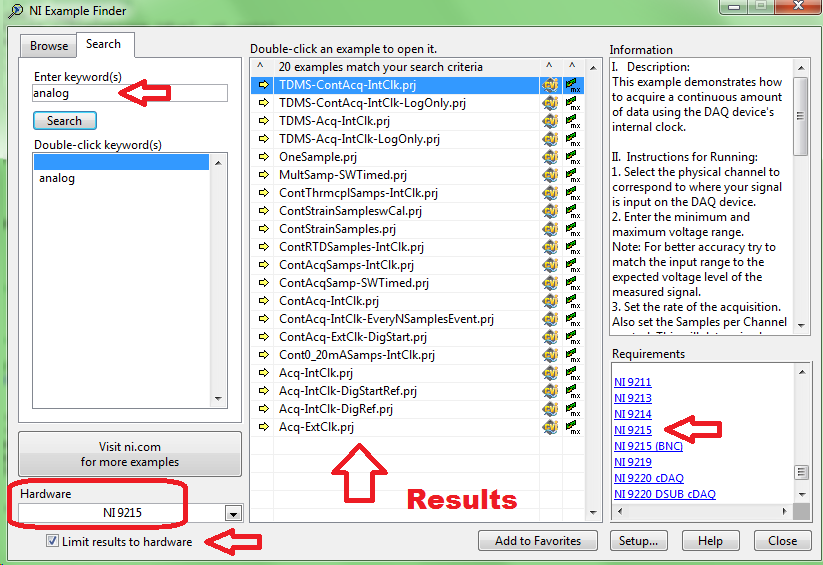
Looking for examples of 9184/9263/9215
Well, obviously, I flood the forum tonight.
I've never used NiDAQmx before, so I'm looking for examples of code in CVI for a cDAQ-9184 with AO 9263 module and an AI 9215 module. I imagine that there are examples of code for hardware compatible with different names, but after a quick search using [help] [NOR example Finder] I could not achieve what either.
Thank you
9184 chassis has no specific software.
If you add the 9215 to loss of material select and check "Limit resusts to material", next search for 'analog', you will find a series of examples which can be executed on the module. It goes same for AO module you have.
Maybe you are looking for
-
One of my accounts will not send, giving a R0107004 error.
For a few days, when I hit 'Send' lacks sometimes, but worked to try again. Today, it has suddenly stopped working. It gives the following message: "an error has occurred when sending mail. The mail server responded: the address must match the authen
-
I know not how to save a window with multiple tabs and windows to reopen command from the previous session, but is it possible - in Safari, or through some 3rd party plugin - to quickly record an entire session of Safari (i.e. multiple windows, some
-
Waveform table, draw and dynamics of double data
Hi all! I would get separate plots on a single waveform chart. In fact, I'm simulating 4 signals (but in reality, it would be the signal from sensors) and I would get 4 plots. In the end, I only get 3 plots and no 4. It's very strange... Yet, I chose
-
Cannot copy files to the CD/DVD to the computer.
Original title: new problem - cannot use Cd/DVD to open files I can do now? I tried to re - install My Documents to my computer. Now, my computer has a CD FULL of Documents recorded, but does not open what can I do? Need repair help
-
Hello... I'm a newbie "to the big 8" and I've never met this garbage and counter intuitive system in my life. I realize Microsoft I struggle to deliver real value for added cost and cannot rely on the bar of the 400% upward that Apple can command (ah