Pressure sensor ground loop problem
Hello
I have an interesting problem, I hope someone can help me with.
I'm measuring pressure with a pressure sensor. We see a lot of noise with the measure, and I believe that we have a ground loop. I have checked the noise is 60 Hz. What is interesting is that the case of the pressure sensor is connected to the Earth. When we put on the sensor of metal pressure in the booth, we see the noise. When disconnect us the stand noise pressure sensor disappears. The stand is connected to the Earth. I'm feeding the sensor with a 24V power supply which is also connected to the Earth. I think that this is the ground loop.
My problem is that the 24V power supply should be grounded for safety and the I cannot isolate the ground pressure sensor.
I attached how I got the system wired. How to connect up to my analog input module pressure sensor OR 9215 to break the ground loop?
Thank you
Dan
Ahhhh Yes,
I have solved this problem. It is a ground loop. I had the field related to 2 places.
We have removed one of the references on the ground and poof everything worked fine.
One of the problems I've found is a reference of external power supplies and others do not. If you provide an additional reference to the Earth... Ground loop!
Ground loops can be mean terrible things. According to my experience, they are the number one electric goofiness and the noise causes.
I have compiled some resources on my website to help people
http://www.autosofttech.NET/resources
The best is field wiring and considerations of noise for analog signals
If you want the final word on the subject see this book
Techniques of reduction of noise in electronic systems
Hope that helps!
Tags: NI Hardware
Similar Questions
-
PXI-6224, SCB-68, power supply for pressure sensor 9-28Vcc
I use a block of SCB-68 connection to connect a Honeywell FP2000 series pressure sensor to a PXI-6224 DAQ module. The transducer requires 9-28Vcc, but the connection block seems to have only 5v pinout. Do I need to use an additional power supply to the transducer?
Yes.
Don't forget to connect the ground from the power to the Gnd of the AI of the 6224.
Lynn
-
Equium M50-244: loop problem internal ati2dvag.dll
I had a M50-244 XP Home Edition (sp2) who have ATI onboard until I uninstalled it completely. The laptop has become totally useless vomit ati2dvag.dll inner loop problem and nothing seemed to heal so I decided to completely get rid of ATI.
It started with VGASAVE which, with a few adjustments, work is fine and so my machine now. I disabled the video as controller he kept coming up with "new hardware found" and I didn't load the drivers more who would do what he started crashing again.
Currently its on 'test' and I'm doing everything possible to see if it will crash once again, I hope not.
Maybe I need another driver and activate the video controller, but I am hated for doing anything more now that his works normally, finally!
Some said the installation of the graphics driver on the site omegadrivers.net and improves the performance of the graphics card.
Maybe an installation of the driver from the site could be useful.Check it out
-
NEITHER USB-6008 connect to thermocuples and pressure sensors, control valve
I am endevoring to build a gasification plant biomass for bench scale test process control plans. NEITHER USB-6008/6009 will be adapted for use as a data acquisition. I'll take RTDS, thermocouples and pressure sensors. I don't want to use industrial automation controllers. It is also possible to use the channel of analog output for sending signals to a control valve position (using sufficient current/voltage between the two drivers).
(1) OK. I just wanted to be sure that you were aware of the potential dangers.
(2) an RTD is a resistance that has small changes in resistance per degree of temperature change. To measure that you have need of a current source and a sufficient resolution in order to detect small changes. At 25 degrees C a typical RTD is 109,73 ohms and resistance ohms 0.38 per degree changes. If you had 1 my crossing this RTD voltage through it would be 109,7 mV and the voltage change of 0.38 mV by degree.
The resolution of the 6008 on the most sensitive range is 0.49 mV > 1 degree. The accuracy of the 6008 is 1.5 mV typical.
For a Type K thermocouple, voltage at 25 degrees is 1.407 mV and change by degree is 39 µV. Millivolt solving half of the 6008 translates into about 12 degrees.
If you need a source of excitement for RTD and a kind of amplification for thermocouples and RTD before she would make any sense to try to use USB-6008.
(3) I have not used anything except LabVIEW with DAQ devices and drivers. I think DAQmx can be used with MATLAB and other languages.
(4) the 6008 is the low range made by NOR. You will need to go to a more expensive camera or add signals conditioning circuits. Talk to your representative OR assistance in the choice of a suitable device.
Lynn
-
Certificate of scaling of pressure sensor
Hello
My pressure sensor has the following calibration certificate:
(lb/PO2) pressure unit of data (mVdc)
--------------------- ---------------------------
0 -0.275
100 49.824
200 99.774
100 49.844
0 -0.264
Balance - 0.275s mVdc
Sensitivity: 100.049 mVdc
Calibration factors:
Sensitivity = 20.01 mV/V
the = 5 VDC voltage will give a result of 0 to 100 mV
I'll use DAQ support to take the measure of pressure.
the question is: what should be the two electric and two physical quantities (IN mV/V units) that I need to enter using DAQ Assistant when you descale the pressure transducer by the method of the colon. Once again, please specify the values in mV/V units.
Thank you
wisjaf12,
You can choose one of the two points at your convenience.
For example: First Value: 49.824 second value: 99.774. (Electricity). First value: 100 second value: 200. (Physics)
CarmenC.
-
Hello
I wonder if anyone has used a sensor of barometric pressure with myRIO Council. If Yes can you suggest any probe good accuracy?
What of it? http://www.embeddedadventures.com/barometric_pressure_sensor_module_mod-1009.html
It will work properly with myRIO?
Thank you
Christos
Hey Christos,.
Looking at the sensor as you linked, which should work perfectly with the myRIO. It uses the I2C/SPI protocols to transmit his readings to a controller, and the myRIO dedicated pins for I2C/SPI communication. Therefore, you should have no problem pulling measures the pressure of the probe.
The myRIO has also 3, 3V output for external sensors power PIN, so you should be able to feed the sensor directly from the myRIO as well.
I hope this helps!
Ryan
-
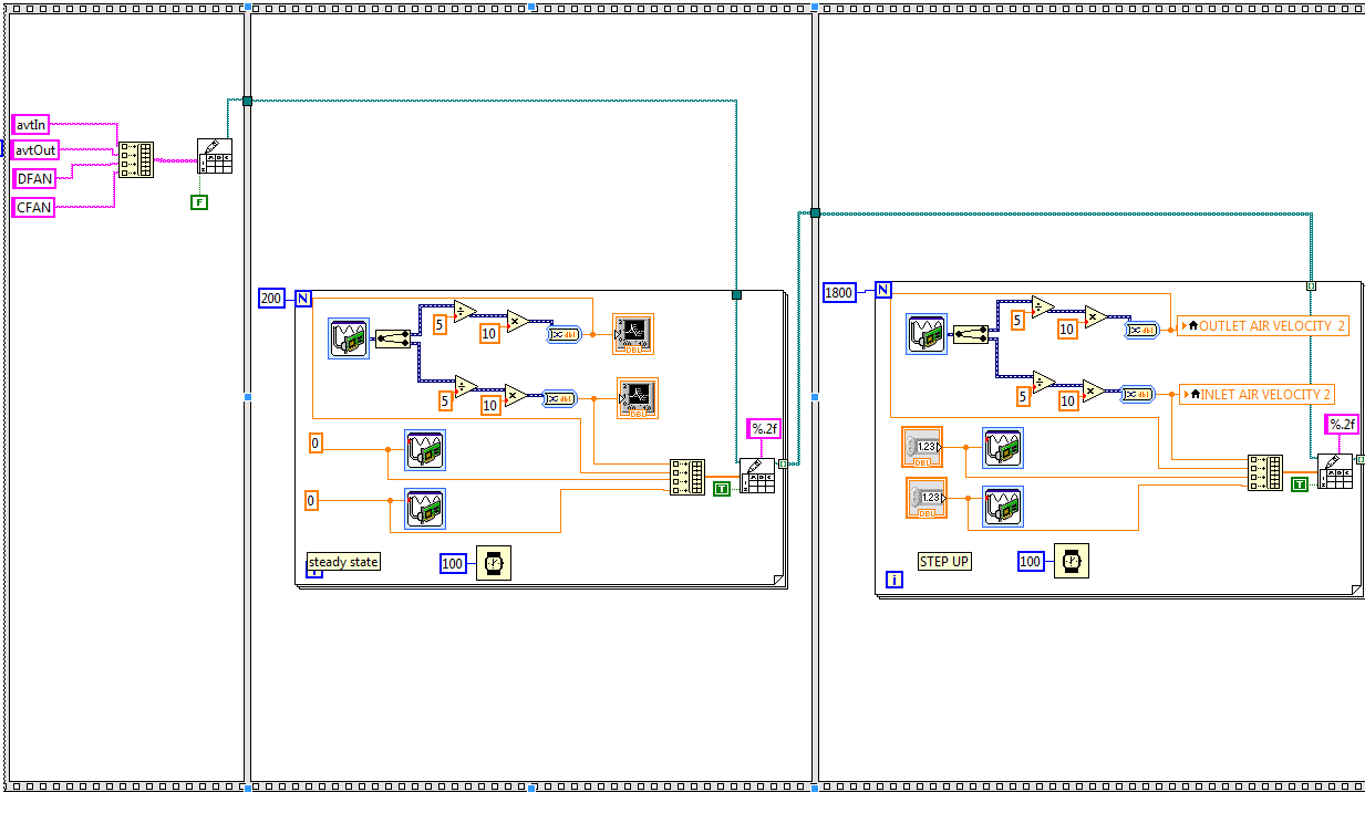
Hello!
I built this vi to record the data of air speed sensors two and analog signals that drive the two actuators. My problem is: the number of iterations, I put on the second image, the same number of iterations will be held at the third picture. The example below, I put initially the loop run for 20 seconds and the second loop to run for 3 minutes. When I run the program both loops ryn for 20 seconds. Any tips?
Concerning
It's because of the release of the first loop table. A for the loop performs an iteration to the smallest size of County or an array of N. You simply need to right click on the output, and then select disable indexing. No need to create an array of file names.
p.s. Get rid of the structure of the sequence. It is not necessary.
-
Out of reading 2-wire 4-20mA pressure sensors using the NI9203 module
Hi all, I'm sure that a lot of people can give a response would we apply for this.
While looking at the wiring diagram on some pressure transmitters (2 wire 4-20 mA output, direct wire), that I'm about to buy, I noticed a slight inconsistency with the wiring in the NI9203 manual. Here are links to manuals for sensors:
Following the manual of NI9203, the + ve terminal of power supply (24Vdc in my case) must be connected to the Brown Terminal in the transducer and - ve supply ground COM on the NI9203. This leaves the Green Terminal in the transducer must be connected to AI0... AI7 on the NI9203 module. This provision makes perfect sense to me. However, the user for the transducer manual suggests that the Terminal green must be wired to zero volts land i.e. COM. This configuration makes less sense to me.
My question is, the internal electronics of the transducer released still the same my current for the same measured pressure given by the curves of calibration for sensor, even if the Green teminal is not connected to zero volts?
I have a hunch it's okay, but I wanted to be sure before that I lost many years spent money / bad record pressure. This should be a matter for manufacturers of sensors I know, but I found this forum is * much * more useful!
See you soon,.
Chris
Hi Chris,
The 9203 is a device for current descendant be plugged on one side common or 0 volt. You must connect your pressure in 2 wire mode sensor.
+ 24 v DC to the positive terminal on your sensor pressure 1 terminal or brown flying lead, Terminal 2 green flying lead is connected to AIx on your 9203 and the commune of the 9203 connected to 0 Volts on your power supply.
All 2-wire device used in a current input down is still as cable + volts then 2-wire device + then then 2-wire device - (or 0) then HAVE + then common then 0 volt.
In my experience the 9203 can be rather prone to noise pick up devices with 2 sons and need a suitable clean power supply. For 2-wire devices, I take 1024 readings and then averaged to reduce noise.
See you soon
Stephen
-
"Setup is preparing your computer for first use" loop problem
Hello, I was hoping you guys could help out me with a big problem, I ran across when trying to install Windows 7 on a desktop computer new, custom - build. I managed to successfully install my Windows 7 64-bit, it appeared, but when I try to run it, that I will meet a black screen that says "Setup is preparing your computer for first use" and it will stay there forever, I would say. I let it run all night and didn't go anywhere.
I tried to start in safe mode, and Windows was loading files sys32, he got to "Classpnp.sys" and it froze. After a few minutes, the screen is blacked out, and I got fired the familiar screen "Setup is preparing your computer for first use.
I bought the copy of Windows 7 nine FRY, there will be no problem with that. My HD is a (new) 240 GB PNY Optima SSD, my mobo is a (new) Z97X-SLI Gigabyte, and I have 16 GB of RAM. All these things have been recognized by my BIOS, it seems that everything is properly connected.
I tried to install Windows 7 on a second time and exactly the same thing happened. I also tried to repair the installation to start upward, but he finds no problems. Also a check of the memory and the disk has verified without any problem. The only things I plugged are my monitor, keyboard, and mouse.
Does anyone know of a workaround for this screen loop "first use"? Any help would be greatly appreciated.
Set of utilities to test for computer HARDWARE manufacturers:
Note: If you are Overclocking or use an automatic overclocking or BIOS power saving features, start by disabling: Intel EIST, Turbo Mode, Cool and pretty and fall back to the speed of stock as a starting point.
Disconnect any other (additional) internal hard drives and external USB devices.
Look for any loose hard drive power or cables SATA, graphics card or other power cables.
First run Memtest86 +:
It runs from a floppy disk or CD and should eliminate or confirm if one or more of your memory
sticks are bad or the values of the SPD in the BIOS are correct.
Let it run for as long as you can: 2,4,6,8 or several hours (at least 3 full passes), if no errors at that time then your ram is OK.
Memtest86 + Guide/How To (use the.) ISO to create a bootable CD)
http://www.overclockers.com/forums/showthread.php?t=409152
Test your hard drive
Intel® drive SSD Toolbox
https://Downloadcenter.Intel.com/Detail_Desc.aspx?AGR=Y&DwnldID=18455
Corsair SSD Toolbox:
http://www.Corsair.com/en-us/blog/2013/may/the-Corsair-SSD-Toolbox
Toolbox of Kingston:
http://www.Kingston.com/us/support/technical/sandforce_ssd_toolbox.aspx
OCZ Toolbox: http://ocz.com/consumer/download/firmware
Support PNY: http://www.PNY.com/support/contact-us
Samsung Magican review:
SanDisk SSD Toolkit: http://kb.sandisk.com/app/answers/detail/a_id/9328/
Seagate: http://www.seagate.com/support/internal-hard-drives/laptop-hard-drives/laptop-600-ssd/
Life of the SSD: http://ssd-life.com/
= Is installed after Windows =.
Device drivers: have you installed latest drivers from device of the manufacture of the motherboard?
Check their support site for the latest drivers as the CD that came with the computer
or motherboard may be older and less stable drivers.
Visit the download of the manufacture of the graphics card:
Download and install the most recent Windows 7 or 8 drivers for your card.
ATI: http://support.amd.com/us/gpudownload/Pages/index.aspx
NVIDIA: http://www.nvidia.com/Download/index.aspx?lang=en-us
See also the test of 'Smoke box' Nvidia or other demos: http://www.nvidia.com/object/cool_stuff.html#/demos
or equivalent ATI.
Prime 95:
http://www.Mersenne.org/freesoft/
It's a stand alone .exe file contained in an archive .zip.
Simply choose to run the 'stress test' option for 8 hours or more.
If your PC can pass this test, your memory and CPU
are very good (close the housing cover in order to maintain adequate ventilation)
Core Temp:
The temperature of each core of the processor.
Note: For the overclockers using stock radiator and cooling fan Intel/AMD you can expect
a range of 35 to 40 at idle and 60 to 65 C max temperature when running Prime95.
http://www.alcpu.com/CoreTemp/
CPU ID (CPUZ): http://www.cpuid.com/cpuz.php
Watch the clock speed of the CPU under various conditions of loading
(when using speed step technology Intel EIST).
#1 Note:
CPU - ID has two tabs - tab 'Memory' that shows the actual speed of the memory
and the "SPD" tab shows the nominal speeds for each memory location that is filled.
#2 Note:
Compare the two values, the actual speed of the memory must not exceed the rated speed of your memory.
CPUID HWMonitor: Hardware program that reads the sensors of health main PC monitoring systems.
voltages, temperatures, fans speed.
http://www.CPUID.com/HWMonitor.php
Speccy:
Advanced for your PC system information tool.
Need to know what's inside your computer?
No problem! Speccy will give you all the information you need.
Note: May or may not show the motherboard manufacturing.
Overview: https://www.piriform.com/speccy
Free version: https://www.piriform.com/speccy/download
Test of Stress of FurMark GPU (graphics card):
http://www.oZone3D.NET/benchmarks/fur/
Pass marks burn in test: http://www.passmark.com/
Burnin test, and their test bench at the same time give a good workout from all the major parts of Windows.
HD Tune:
Provides information of the car and has an option (tab scan error) to test your drive.
CrystalDiskInfo:
http://CrystalMark.info/software/index-e.html
User Manual: http://crystalmark.info/software/CrystalDiskInfo/manual-en/
Monitors the State of health and the temperature. Solid State Drives brackets (value of the software).
SpeedFan:
Monitors internal temperatures and has a function of analysis health online (SMART tab) for hard disks drive.
It displays your drives model number and compares your drive with other discs of the same brand and model.
Note: Unfortunately now includes a lot of bloatware, be very careful when installing remove bloatware.
http://www.almico.com/SpeedFan.php
GPU - Z:
A utility light, designed for you give information about your video card and GPU.
http://www.techpowerup.com/GPUZ/
PC WIZARD:
A powerful utility designed especially for detection of hardware, also analyses more.
He is able to identify a large scale of system components and supports the latest technologies
and standards.
http://www.CPUID.com/pcwizard.php
J W Stuart: http://www.pagestart.com
-
Calibration of pressure sensor
I have two pressure omegadyne transducers. I tried to calibrate the transducers via linear equations. The problem is that when I put the second slope of line transducer and the y-intercept, the first (slope of the line and intercept) changes automatically to the second parameter. Transducers are mounted on two different channels. I can't have two different equations for the two transducers. I appreciate it if anyone has a solution to this.
Concerning
Ali,
When you're in the DAQ Assistant, on the configuration tab, in the input parameters of voltage is a Custom Scaling pull down. If you who pull down, you can select Create new and which will allow you to install a custom scale for each transducer if you wish. Just assign the custom scale for the appropriate channel once you have created the custom scale.
If you use the same transducers of beach and they have different slopes... I refer to them and buy some finding themselves in a few percentage points of each other on the range. No one should sell you two producers of trans who have the same range that do not use the same slope... the y originally I see who need some tweaking, but not the slope! .. just in my opinion. I sent a lot of return of material that does not perform or has not been linear in its response. ... again, just my opinion.
Enjoy!
Chad
-
Hello
I use a power supply (kepco BOP 100-4, if it helps) and control using a card PCI-6221. I am also able the current and voltage in the circuit of load using the same Board.
Feeding is a floating source, but took me to the Earth, so for measures to HAVE it, I use the differential mode. On the power supply of the entry and exit have the same pattern, so I was wondering if there was any risk of a loop of land due to the GND AO?
Thank you
scalpas:
I think that all the grounds (digital I, AO,) are bound to the Earth in the PC. If you have an ohmmeter, with PC and unplugged, look for continutiy between a GND pin on the acquisition of data and the metal casing of the PC part (case is usually connected to AC power grounding).
-AK2DM
-
multiple inputs and nested loop problem
Hello world
I'm using Labview 2009.
I want to change the value of a variable by using the wheel or keyboard.
So I downloaded a button and the screws of the keyboard that suits my needs of multi-rotation forum.
These two screws are running inside a WHILE loop. Because I would be constantly updating the variable I will run my main screw that houses these two screws also looped a WHILE.
Problem is that while loop within a while loop
 I couldn't run my main VI because of this problem.
I tried in 2ways
1 including them as an auxiliary in my main VI but as the two screws screw contains a few other variables inside of the inside while loop that LabVIEW displays error as auxiliary screws will not work
2. I also tried to copy paste the two screws as it is in my main screw but could end up only in a lot of errors.
How to deal with this problem of nested while loops?
Please guide me.
Kind regards
Maury
You make a mistake of data flow. The outer loop can turn only if all of the code that he has completed. The structure of the event cannot complete because inside while loop has not finished, and if inside so that the loop ends, the loop cannot turn because the structure of the event stalls. You can only go to the next iteration after all both have completed, from the mess.
All you need to do to incorporate ALL the code inside the structure of the event. Attached, it's a simple project (LV 9.0), modify as necessary.
See if it makes sense for you. (there are a few minor bugs probably)
-
Spectrum of HP X 2 - HID SENSOR COLLECTION driver problem
Hello
I just bougt garage a Ultrabook of spectrum HP X 2/tablet.
Since I already have a Windows 8 N Pro license I installed it on my spectrum X 2.
The question I am now face is that the dirver HID SENSOR COLLECTION is not woking and I can't use my sensors such as: rotation (accelerometer), light sensor, the screen...
I can see this error in Device Manager by double-clicking on the HID COLLECTION of SENSOR:
"
This device cannot start (Code 10).
The process hosting the driver for this device was completed.
"
I have installed all drivers HP of my spectrum HP X 2 page drivers and I also installed all Windows updates.
Can someone please?
Thank you
Mircea
I found a solution for the problem of driver HID sensor Collection.
It seems that the driver uses something Windows Media Framework and because it can not find it on my spectrum X 2 it fails.
This driver problem will happen on all the HP spectrum X 2 who have installed Windows 8.1 Pro N (N is the European version) because there is no Media Feature Pack installed by default.
To fix the driver HID Collection sensor problem, I installed the Media Feature Pack for N and KN here 8.1 Windows versions:
http://www.Microsoft.com/en-US/Download/details.aspx?ID=40744
After the instalation just sensors begin to work.
It is a BIG PROBLEM and HP needs to do something about it!
A big thank you to Wiab of Lenovo Comunity forum for us to share the solution:
Kind regards
Mircea
-
Case of Structure / while loop problems
Hello
I am trying to write a code that draws a random number whenever a key is pressed. The chart must be a random number on the y axis and the number of times that the button is pressed on the x-axis. I want to draw the last twenty random numbers. I use a while loop and a box structure. If the button is pressed, the case structure incruments the number of times where the button is pressed and generates a random number. I'm using shift registers to track the last twenty numbers generated. When the key not, registers to shift to day values incorrectly. My code is associated with this issue.
I know that the last value of the shift registers of wiring to the structure of the case will change the table across the last value when the button is not pressed. I know what causes the problem, but I don't know how to fix it. I would appreciate it if you have a look and give me some tips.
Thanks in advance.
Your problem is that the loop runs continuously and your values in the shift register are replaced when you do nothing.
There are a few ways around this. It would be simpler to use a Structure of the event. Another option is to simply store your table in the shiftregister. Use Rotate 1-d Array and replace a subset of table to update your chart. It is a little more robust and easier to use than using the history of the shift register.
But the absolute simplest, based only on what you told us, just use a graphic instead of a graph. A graph keeps a history. The length of the default history is 1024 samples, then you want to reduce that to 20. Then you just wire your random number right in the chart, and everything is done for you.

-
Table 1 d in the while loop problem
Hello world
I searched this problem in the forum, but seems only some positions quite didn't answer.
I'm stuck by saving the data in a while loop.
I have a while loop, within which there are two exits in each iteration, I want to add to a table, and then after the while loop is completed, I want to combine these two tables in a 2D array (since the release of them must be a pair in my case).
I tried 'Build array' and 'transpose array' and 'write in spreadsheet' element set, which maintains concerns me is how simply to add the result in a 1 d table during each iteration, these 2 outputs are in digital format, which prevent to directly create a table for it.
Any idea is appreciated,
Thank you
Chen Kunsheng
Here are some other ways to insert.
It may be useful
Maybe you are looking for
-
Satellite P300 - 19F DVD does not work
I have a Satellite P300-19F with Win Vista 32 bit Home Premium SP2.I can't read any DVD. It does not show a corresponding drive letter.If I go on under control panel Device Manager - system, it recognizes a Pioneer DVD - RW DVRTD08A, but has a warnin
-
Why my phone will not connect to my wifi
Why my phone will not connect to my wifi
-
Local variables of logging into a database
Hello! I followed the instructions in 'Logging again USE property to a database in TestStand' to be able to log my local variable under the Options/columns/parameters/Expression database. My problem is that I can't access my variable in the Expressio
-
Loss of Internet connection momentarily WAG354G
Hey everyone, I use a WAG354G router, connected to the phone line by a "Speedtouch ADSL Filter" which divides my line "Modem" and "phone". Every so often, about every 5 minutes or so, I lose the internet connection for about 20 seconds, before it rec
-
Cannot access the user account
I recently sent my computer in my college of departmental it to update some software. They could not access my account due to a password. They bi - passed this by making two accounts 'Test' and 'comments'. If I'm going to one of these accounts I can