Problem of reliability data acquisition PXI-4071
Hello
I'm having a problem of reliability using my 4071 Pxi digitizer mode.
I have a number of tests that use the SMU-6363 (usually configured for DC) analog output to provide a stimulus for our own device, which has a number of a/d converters. We use the PXI system for calibration and testing.
1. I select a voltage ranging from tensions.
2. program the PXI-6363 to drive this tension
3 TIME about 10ms to settle. Note there no discrete capacitors or resistors in the circuit. Everything is parasitic and would generally be under the nF mark and less than 10 ohms
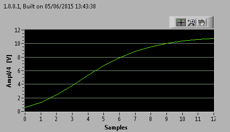
3. configure and Initiate() acquisition of data with the PXI-4071. In general, I use a sample rate of 1000 s/s and get about 30 samples (worth 30 ms). Activation is immediate and I used the default a queue time, 0, set the time and it doesn't seem to make a difference.
4. measure the voltage with the CDA. For debugging purposes I have sometimes made twice once before calling Initiate() and once after. The after is normal. The time required to measure the ADC is shorter than the acquisition time, but regardless of stimulation by the SMU-6363 is constant
5. extract the waveform.
6. the average waveform and compare the value of ADC measured by applying tolerances etc.
Here's the problem: it works well most of the time. But only 0.1% of the time (1 on an acquisition of 1000), I get 8-12 samples that are close to 0. It sounds like a problem of time settling (on the surface), but no matter the amount of wait time data, I always get this behavior. Not only that, but the tension before the call to Initiate() in height CDA, it always confirms that the motor voltage is already set to the programmed value. Nevertheless the acquisition presents near data 0.
So far our independent ADC always reports the expected before and during acquisition (100%) voltage. It's like the DMM input is disconnected during the acquisition during a period of time, because we have confirmed that the voltage is already present prior to the acquisition (component can). I have no errors the insider or FetchWaveForm calls. I still have all my samples. And 99.9% of the time that everything works as expected.
The DMM and ADC are connected to the same point and both are referenced to ground, and as I said before only the parasitic capacitance and resistance (cable). We use a matrix of switching (PXI-2530 (b) to make these connections. We almost always use 51/2 digits and 10V range for data acquisition.
Hello
I thought about it and was going to repost but am distracted.
The device with the ADC also has a mux and switches the mux to an internal node. It only switches when measuring and is open at other times. There is a race condition where the acquisition starts too early and maintains the acquisition after that the switch is open. Unfortunately I don't have the option to trigger.
I forgot the internal mux that I had designed the test years ago and I did some updates to improve the stability of the test. That's why we start the ADC measurement when acquiring.
I just added a routine to reject samples below a threshold
Tags: NI Hardware
Similar Questions
-
How to acquire data through several channels in parallel using E 6070 PXI, PXI-4071 and LabVIEW?
Hello
I use LabVIEW and NI PXI-4071 PXI NOR 6070E to measure the current through a variable resistance. Now, I use a single channel of SCB - 68, but I want to add another channel at the same time so that I can have two resistors instead of one that I cam measure current through them.
I have attached a Pdf file showing installation of equipment to use and code LabVIEW also.
Can someone look at these files and give me some guidelines or ideas that can help me solve this problem, please.
Thanks in advance.
Best regards
Shaheen.
Your 4071 can do a measure at a time. Your data acquisition cannot measure resistance is not she of the analog inputs.
However, you could use a multiplexer and multiplexer your 4071 DMM. This habit give you simultaneous action, but can acquire data one after the other, the speed depends on the multiplexer, you choose!
I hope this helps.
-
Hello
We use the DMM and SMU-6363 map to test a hardware device. We will also use a PXI-2530 b switching matrix. We will use the digital multimeter to perform the measurements of voltage, DC and AC, measurements of impedance (2-wire and 4-wire), frequency and waveform acquisition. Can the PXI-4071 left be 4 wire connected (black jacks taken connected and red connected) mode and still be used to perform all other measures (including 2 impedance of the cable). This would simplify the switch connections.
Current measures use the son + and LO, but the HI and S-can remain connected. The problem you are having is if you have an active device the digital multimeter and take you a 4-wire resistance and the measurement of voltage with all 4 wires connected and then change to a current... When you do this, short-circuit you the terminals of the DUT, on that you just take the measurement of the resistance. If the terminal HAD, say, a power supply 10V, then you have just shorted out. Of course, this isn't a problem if your Instrument is a passive device, or if you change just the unused two lead whenever there is an active device of low impedance.
If you want to make voltage, current and 4-wire resistance, you need all 4 wires. If you want to do the voltage and current, you will need 3 wires, but you could connect the s + Hi and then just do the two wires. I vote running every 4 son to your DUT for maximum flexibility.
2-wire resistance is a must if you are measuring resistance above 10 MOhm. Alternatively, you can use 4-wire for all measures.
-
Hello people,
I recently updated my CalExec 3.4 3.4.1. Desktop XP OS.
I can't calibrate the PXI-4071, I have not had any problems in the past.
MAX has no problem seein' and it makes even the inside however calibration option, with CalExec I get as much as
update from the slot, after that this error... Error-1073807297.
I have attached a hood perforated of all error... can you help out me.
I have a Chassis1042 w / counterpart 8330 PXI AND PCI and PXI-GPIB.
Thanks in advance.
Hey JSOTO,
You connect to any equipment calibration using VISA? If so, you can check that all these devices are rising and successfully through VISA? If one of the VISA alias is incorrect, then could you appears as this error.
My recommendation is to start Trace of e/s OR (formerly known as "NOR-SPY) (start" all programs"National Instruments" NI Trace of IO). Then try to calibrate the unit. I/o path will record all calls VISA and could lead us to the root cause. Once you have saved the data, you can export it and send it to us. If you are not comfortable posting all data on this forum, then you can post only the steps leading to the error or we can contact you by e-mail and continue troubleshooting it.
Tell us what you find.
-
DSA maxing out CPU data acquisition
I'm developing an application on a PXI-8196 (Windows XP) controller that uses a card PXI - 4472 DSA to read a single microphone and a FFT signal analysis. I need solve the two frequencies of 36kHz (and), so I've planned for sampling 96 kech. / s. I wrote a simple loop of data acquisition, configuring NI44xx DAQ/read screws using read the string unique at this rate, but when I run it, it immediately pegs my CPU 100% usage. So far, I did have problems with missing samples or the system crashes, but I am a little concerned that only data acquisition uses all my CPU time. Y at - it tricks that I can implement to reduce the CPU load?
I tried to vary the parameter samples per channel - with sizes ranging from 1000 to 48000 samples - buffer but I do not seem likely to reduce the CPU usage. Changing the sampling frequency affects the CPU usage (up to about 40% to 48 ksps / s; ~ 75% 72 ksps / s), though. According to this KB: http://digital.ni.com/public.nsf/allkb/D9DDF9FA02D1C18A86256EBC0016C93D
"A controller Embedded PXI-8176 can compute all the time of the spectra of FFT power on 8 channels for PXI-4472 clocked at 102.4 ksps / s »
so I think with my 8196 I should have no problem at all to read only one channel 96 kech. / s.
Anyone have any suggestions to reduce my CPU Overload? Thank you!
Here is a link to some good information on how to OR-DAQmx 7.4 and later behaves with respect to the use of the processor: Default CPU use with NOR-DAQmx Version 7.4
-
Why data acquisition in an executable collect fewer samples?
Hello
I have LV2012 on Windows and SMU-6341 map in PXI chassis.
I have a task for the acquisition of data on I-1 on my monstrous application. Well, to get to the point, I have here a case where the task of data acquisition starts, waiting 20ms, reads all available samples and puts an end to the task. For the parameters see the piece attached. Then, the collected data is plotted on a waveform graph. Usually about 200 samples are taken in the case of data acquisition. Then loops shown sequence, until certain conditions are met.
Unfortunately a problem occurs when I deploy a rack application (exe) on a production PC some 600 miles away from me.

This is an example of what I get on my development PC (LV and runtime give similar results):
This is an example of what I get on the production of exe PC (13 iterations, bad luck
 ):
):It totally looks like the data acquisition task mentioned seizes one sample to an iteration of the loop.
I enclose a noodle dragged out of the main program. I'm about to test the version of this noodle on the production of PC in a few hours, but I would like to hear all the ideas that emerge.
Thanks in advance!
cubz wrote: from my experience, the continuous 'Samples' mode does not stop when the buffer is full. The loop of 4 seconds (with 10 k samples/s in the sample buffer 40 k)-that is to say samples how finished works IMO.
If the buffer is filled in continuous mode of the samples, you will get an error. I'm sure it's something you don't want. In this example, you have provided, you really should have finished samples and has said the acquisition of data to read samples of N. It is the only way to ensure you get all the data you want.
In regards to your differences between development and executable, the executable file tends to only not nearly as happening (Debug stuff for the most part), so it tends to run faster. If you're depending on a software clock, anything can happen (having a ton of little or no data). That is why we say you use the clock machine and get the number of samples that you actually want.
-
I get upgraded my laptop (HP for laptop - 15-r224tx) for Windows 10 but I can't find the driver for the controller of PCI Data Acquisition and Signal Processing. Please help me find the right one.
Thank you!
You are the very welcome.
It is the latest version of the W10 driver for this card model... see if this solves the problem, if you have not already installed this driver.
This package contains the installation package driver for the controller wireless LAN Realtek RTL8723BE/RTL8188EE in the laptop models running a supported operating system.
File name: sp72517.exe
-
Hi team,
I just install windows 7 edition integral and peripheral Bluetooth windows 8.1 is not be detectable, when I search for problem that I came across this PCI data acquisition and Signal Processing controller driver is missing and a unknown device driver missing shownup in my result of troubleshooting. Please help me
Please find the screenshot for your reference
Thank you
Hello:
See if these drivers work...
CQI PCI controller:
This package contains the driver which allows Intel platform dynamic and thermal firmware setting. Intel platform dynamic and thermal environment information system temperature and power use for the heat of the system
protection to work properly. This package is provided for the laptop models running a supported operating system.File name: sp71638.exe
Bluetooth:
This package contains the installation package driver for Realtek bluetooth in the laptop models running a supported operating system.
File name: sp71288.exe
Unknown dev:
This package provides the HP 3D DriveGuard software (HP ProtectSmart Hard Drive Protection) for the laptop models running a supported operating system. HP 3D DriveGuard software protects the drive hard by parking the heads if cell phone accidentally falls, or is suddenly struck by another object.
File name: sp71811.exe
-
15 - r235ne: SM bus controller / IBD DATA Acquisition and Signal Processing controller
Hello team
I am facing problem in finding the right driver for material below.
1 SM bus controller
2 IBD DATA acquisition and Signal Processing controller
kindly help
concerning
NASIR
Hi, Nguyen:
Download and install the Intel chipset installation utility and restart the PC.
The 2nd driver down on the left is the automatic installation file.
-
Data acquisition reading incorrect when you use a loop
Hello
I wrote a simple VI (00, 01, 10, and 11) output to a circuit connected with 4 resistors. Based on what value the ciruit receives, it passes current through a particular resistance. It is again entered in Labview and traced.
The problem is when I send a particular value (i.e the 00, 01 and 10 and 11) and get that back, it's okay. But when I send and receive the consectively connected via the loop counter, they are incorrect (not synchronized with the number of the loop).
I made sure that circuit works very well. It has something to do with the loop synnchronization, reset, value compensation, etc. can be.
Please Guide...
Change your DAQ assistant that reads to be 1 sample on request.
Right now it is set for continuous samples. And 10 samples at 10 Hz. Then it runs and starts. The next iteration, you send a new digital out, but the wait for 4 seconds. When you read again, you get the next 10 samples that are put into the buffer of data acquisition, but now 40 samples have actually entered the DAQ buffer. In time your DAQ buffer will be finally complete and raise an error. In the meantime, you will continually read data continues to become more tainted by the iteration.
-
data acquisition won't taste at the specified rate
Material: C - DAQ 9178, AI 9239, inside a servo and an encoder potentiometer module
Setup: I use the 9239 to measure the angular position of my servo and encoder of trees by streaming came pressure pot of the servo and my encoder. I put the sampling frequency on the DAQmx - Schedule VI to 100 Hz.
Problem: I don't think that my DAQ is sampling data at 100 Hz because my VI registers more than 10 000 data points for a 10 second test. In addition, every time I have save my data in a text file, the vector of time my test data resets after a number of iterations.
To debug, I tried the following configuration:
I've defined the sampling frequency of 100 Hz (or is that s/s?), the samples per channel (size of buffer for continuous mode) at 2000 samples, number of samples per channel up to 10 and loop milliseconds timer on my VI at 10 m accordingly, data acquisition would send 100 samples per second (or 1 sample every 10 ms) on my PC buffer (which could store 20 X that amount). Then LabVIEW would read up to 10 samples per loop iteration (which is itself ~ 100 Hz) and work with these 10 samples inside the loop. However, since the loop is operating close to the sampling frequency of data acquisition, then LV should only work with 1 sample each iteration of the loop (100 Hz / 100 Hz)-not the 10-sample-max that I specified.
However, I stumbled on "error-200279: the application is not able to cope with the acquisition of material" when I ran the program. Why?
My code and materials should be easily able to cope with data acquisition - at least the way I put it in place
This whole situation wondered my fundamental understanding of data acquisition timing, so I would really appreciate an explanation of exactly how to deliver DAQmx uses data synchronization, why my DAQ sample at 100 Hz, and how can I fix the calendar specified by the user.
Thank you!
aeroAggie wrote:
The C - DAQ 9178 there some minimum sampling rate I will not meet?
It's actually the 9239 that limit your sampling rate. Read the data sheeton page 5 there's available data rates. In short, your data rate allowed is 50kS/s / n, where is goes from 1 to 31. 50 k/31 gives you 1.6kS / s. So, it's the minimum sampling frequency that can be used.
-
PXI-4071 sampling too slow when using a hardware trigger
We use 3 PXI - 4071 s in parallel to measure with accuracy of high voltages. The program is written using LabVIEW 8.5.1.
An additional test condition has been added which requires the use of a quadrature decoder and the synchronous DMM.
We thought it would be simple, using backplane trigger 0.
However, something odd happens.
With a low-cut VI that uses a single DMM, we get 100 microseconds time to sample running with internal triggers. However, if the overall relaxation or trigger of the sample is set to TTL0, the sample time becomes so 5.1 milliseconds. It seems very strange that even just definition of overall relaxation, expected to affect only the time of the first sample, not the time between samples, has that effect. The plug for the DMM also said, that the maximum trigger rate is of 6 kHz.
We have confirmed this reported sample time is independent of the speed of the clock actually connected to TTL0. If the clock is faster, it gets the reported sample time. If it's slower, the samples occur on the edges of the clock.
Does anyone know if there is a parameter that has a default that changes based on the source of command and can be changed to work around this problem, you?
I found the solution to this.
Over time the value-1, the DMM uses a short value (less than 100 US) to set hour when, in modes triggered internally. However, he used much longer (about 5 ms) when the value - 1 and with the help of a hardware trigger.
If the running-in is set to 1e-5, i.e. 10 microseconds, "the estimate" returned for conversion period goes from 5.1 ms 100, we and conversions actually occur at a rate set when clocked with trig 0-5 kHz
-
data acquisition stops automatically
I want to stop assistant DAQ automatically after a period of time, so I created this VI.
When I start the program, it work and after reaching the value of time specific 50, the graphical indicator ' looks like "stop, but wait after 9999 second, the graphical indicator suddenly see a lot of data that seems to be taken for the 9999 seconds, what is happening? After that, it gives an error saying:
Possible reasons:
Attempted to read samples that are no longer available. The requested sample was already available, but has since been replaced.
Increase in the size of buffer, most frequently the reading of data or by specifying a fixed number of samples to read instead of reading all available samples would correct the problem.
Property: RelativeTo
Corresponding value: current playback Position
Property: Offset
Corresponding value: 0Task name: _unnamedTask<100>
Data acquisition cannot be stopped like that?

Thank you
Not quite. Like this.

-
Error-1074118625 with the PXI-4071 and PXI-2527
When you use the LabVIEW and PXI-4071 PXI-2527 IVI drivers, I get a 1074118625 error in TestStand. The sequence that initializes the MUX, init DMM, connects the MUX, expected debounce, and then to the DMM reading, I get this error.
Error: niDMM .viExplanation of waveform (waveform data) reading is not found for the requested status code.
Check that the required status code is correct.
[Error code: error code defined by the user of 1074118625.]
This sequence of events is used successfully several times elsewhere in the TestStand. This error does not appear in any section of the knowledge base, or any help. Any explanation would be greatly appreciated.
I found this with google that seems like it could apply:
http://digital.NI.com/public.nsf/allkb/A593DEBFD86A69C68625727900748EEC
-
LeCroy Waverunner 640Zi - Data Acquisition
Hello... I'm trying to set up my oscilloscope waverunner with LabVIEW SignalExpress for data acquisition.
I took the steps so far:
1 pulse generator hooked to scope of signal generation
2 USB scope to the installed computer with LabView
3 downloaded lecroyscope driver 3.2.9 - x 64
I turn on the scope and plug in the USB to the computer and SignalExpress begins.
a. start by using data acquisition
b. Add step/aquire signal / IVI aquire / IVI brought aquire
c. create new IVI session... resources descriptor (I choose my USB device ' USB0::0x05FF:0 x 1023: 2812N61507:INSTR '), I select the right driver (lcscope), and I do not click enable simulation data, press ok
d. I still receive configuration errorse. did the research... some forum said goto MAX, find drivers and uncheck the Cache and the exchange of check
f. attempt to initialize... always get config errors.
g. return to MAX... change to simulate with specific driver.
h. initialization works... NO errors, BUT no data are acquired.
Help, please!
Hello
Sorry to jump in if I was out of the country for a while and am still catching things in my office.
I think you are looking for someone to say yes, "you can connect to the scope with NOR-MAX and VISA, and here's how interactive tool do"
A few things:
LabVIEW for XStream extended driver is the right one. It works with all the TeledyneLeCroy Windows based scopes.
As I see has already been noted. (I'll give Kudos soon), the scope of application must be configured to use interface USBTMC. To do this, go to the drop down Utitlites on the scope menu and select "utilities configuration... '. "in the tabs that appear at the bottom of the screen, select the 'Remote' tab and make sure that the interface type is set to USBTMC. This will also show you the VISA resource (I see it in the title of the image of VISA interactive tool indicated in a previous post).
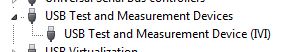
Once this field is selected, the PC should detect the USB connection and install the device. (you can see in your device manager as a Test of USB and the measurement device):
Once this is done, you can then enter the NOT-MAX and it will detect and display resources. You can now communicate with the device:
If you have problems, do not hesitate to give me a call and I'm happy to walk through it over the phone.
Kind regards
Leonard Brown
Technical sales engineer
Teledyne LeCroy
1-800-553-2769


Maybe you are looking for
-
Hello Supposedly it is possible for the content to iTunes on a Mac, an Apple TV, when they are in the same network. I did pretty well with my Apple TV 2nd generation. However, when I bought the 3rd generation Apple TV, it does not any computer on t
-
Hello IM karaar How to reset my security id appke questions
-
I show two updates of security with a date of 1969 is that right
I show two updates of security with a date of 1969 are those just my Fox fire beginning very slow very very slow This has happened Each time Firefox opened Is a month ago
-
Utility supervisor password does not work after update Vista
I updated my computer that I brought in October 2006 PSP AOE P100 227 to Vista.I noticed that the supervisor password utility does not work. I downloaded the new software for this toshiba that was released yesterday but the wissard installation conti
-
When will they be released? Links for docs are present: https://bdsc.webapps.blackberry.com/cascades/reference/bb__multimedia__mediaplayer.html , but no page exists