Problem using labview and GPIB
Hi guys,.
Finally got recognized my tool GPIB in labview, which is nice. I created the block (attached you can see you diagram) but it works like 20 sec. I press run continious and I can change the values in direct mode, as I hear it. But then after 10 seconds, it appears the error that is in the screen and only works again if I reboot the function generator.
The model is Tektronix AFG3102.
Concerning
Tags: NI Software
Similar Questions
-
Communication problem between LabView and acquisition of data USB 6259
I want to monitor a data USB-6259 acquisition using LabVIEW 8.6. However, when you try to create an explicit task (using the DAQ assistant) in order to acquire a signal, I get the message asked supported device found¨. I can see the USB-6259 under ¨Devices and interfaces¨ to the MAX, but when I try to import the configuration data for NOR-DAQmx 8.7.2 in MAX, I get the message ¨Can´t import file configData.nce. File not found¨. I use NEITHER-DAQmx 8.7.2. Any suggestions?
Corneliu
Hi, Corneliu,
This question could be generated due to a corruption of database of MAX. Here is a link to restore the database to the MAX.
http://digital.NI.com/public.nsf/allkb/2C7480E856987FFF862573AE005AB0D9?OpenDocument
Just follow the steps and let me know if that solves the problem.
A greeting.
Jesus.
-
Time real ADC/DAC for SMPS by using Labview and USB
Hi all
I asked the Sales Department of this same question, so here's a two-pronged approach:
I am reserching a control algorithm for power switching, and so far, its performance simulations seem to be good. Now, the goal is to implement the circuit from the experimental data.
I've seen several NI USB DAQ boxes that seem to have the performance, I'm looking for (for example, the box USB-6211 a sampling rate and resolution I need).
The control algorithm uses the following mathematical functions: add/sub/mult/div/exhibitor and derivative/integral.
My question is this: is "strong enough" Labview take four-channel data 250Ksps, crunches the numbers in an equation and spits out the answer to an analogue on the channel, while time REAL? I'm looking for a rate of analog output of ~ 100 kHz.
Thank you for any suggestions you have!
-Rick
Hey,.
So if you were trying just to perform an input or output, then the box USB-6211 would certainly be able to treat it as the machine clock could manage the inputs/outputs, no software. However, what you are wanting to do, basically a feedback system, he will have to avoid (at least to a USB device) because you need to be able to specify Active which is the output. So, for this reason alone and the fact that you want out of 100 kHz, this device and the USB devices in general will be not an option any what software you use, LabVIEW or otherwise. On another note, you want to make sounds more like live update, not in real time, which is more on the jitter. Bottom line, for these kinds of requirements, you might need to move to an FPGA card, something like the NI PCIe-7841R would work. It's more expensive, but for your needs, FPGA will be the only option and it comes down to the latency of the bus, but also the response time of software. With FPGA, as shown in the first scheme of the following document, you basically close your software through hardware loop.
Basics of FPGA
http://www.NI.com/white-paper/6983/en
-Ryan S.
-
Recognition of map to play using LabVIEW and a webcam
Hello
For our project in my school (2nd year of electronic engineering), we are a distributor of Blackjack robot. In the help of LabVIEW and a webcam we'd like to take a picture of the card he's going to face and then compare it to a database, we did prior to that the program knows which card it is.
So what we really want to do is
-scan the card he'll deal with (take a photo of him)
-compare with our database of predefined photos of all playing cards
-Once it has good info is obtained, channeling through our program so that we can count and whatnot with this card.
-He needs to recognize the value of the card, not the type (i.e. must know that it is a 4, not that it is a 4 diamond)
I have not found a good solution, again, can someone help us project? Any tips are appreciated with kindness

Kind regards
Vincent
-
Problem between Labview and Melanie 2602
Hello world
I think my question is a bit silly, but I really don't know what the problem is. I just want to read my current solar cell by changing the level of my blood to get an IV curve, which is normally pretty easy. So, I created a loop, where I increase my voltage step by step, and used a function named VI from Labview library that connects the Keithley and Labview together, "Keithley 2600 Series.lvlib: Source Level.vi. I start at 0 and increase by 0.01 volt each time. If I use execution of climax, I see clearly the value is correct, and if I go inside the SourceLevel VI, I clearly see the command string: "smub.source.levelv = 1.6," for example, if I want to put my voltage at 1.6V. The attached picture shows a part of my code.
Despite all this, it is clear that the Keithley does not react properly. It only works v of v 1V, 2V, 3V, etc... but never the values between. My IV curves are ok to read the Isc, but no VOCS. Never happened to any of you? I would be really happy to understand what I'm doing wrong, because it seems easy enough to solve. :/
Thank you very much!
It is quite difficult to debug a picture of a tiny part of the code.
But I'll take what I see. Your constant shows a 0.01 (comma). So I guess that you are in a country that uses a comma instead of a decimal point. I don't see what is happening inside the code Keithly, but I'll make an assumption that he made some conversions where it is expected that the comma is a period.
Look closely at the code Keithly and see if that explains it. Try to set your PC to use a period for the decimal point and try to re-run your code and see if it works better. It is possible that Keithly conversion uses a system, rather than setting using a decimal point, which is that your sentence says it's sending.
-
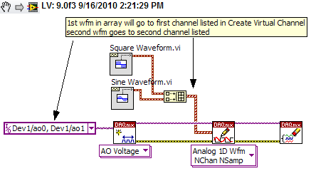
Using Labview and PXI-4461, how can I AO0 output Signal Square and AO1 output waveform
I am using PXI-4461 and Labview, boredom, generating 2 signals simultaneously.
How can I get AO0 out square and exit AO1 SignWave?
Help, please. (The example Code would be nice)
Thank you.
Create two signals and make a table with them. Use DAQmx Create Virtual Channel to create two channels. First waveform will be sent to the first string, second waveform on the second channel.
I understand not all as calendar, clock frequency, amplitude, trigger and other parameters. You can add these things. This is just a basic example.
-
Using PCI and GPIB-Enet drivers set
We need to use a PCI and Enet GPIB controller at the same time under Solaris 9.
Is this always the case that it not there no driver unified for the PCI GPIB card and the Ethernet GPIB for Solaris (Solaris 9) controller, as shown in your post on the forum of April 2004 (pfrogers and JoshuaP)?
If there is no unified driver, is it possible to install two drivers in different directories, and then compile a program that will access both devices having carefully he use different files for header C and libraries, according to what access controller? It seems to me, the answer will always be no, because your API GPIB function calls will have the same name between the two controllers, so there is no way to specify what (PCI or Enet version) function to call.
Thank you.
Hello
Thank you for your message. Yes, it's always the case that there is no unified driver for the PCI-GPIB card and controller ENET/GPIB for Solaris 9. You are also right in your assumption that you will not be able to compile a program that will allow you to access these two drivers in different directories. I apologize for the inconvinience this may cause you.
Have a great day!
Kind regards
Todd v.
-
Choose and place using labview and or vision acquisition
Hello world
I'm doing a project studying on Vision guided pick and place of a robot (abb) industrial. I would like to know the steps involved in the creation of the block.
I locate the object, move his webcam cooordinates. Then made a pattern match, and would send the cooordinates to the microcontroller. then from microcontroller for control of robot... then the industrial robot should choose the object and place it in a predefined area...
I would be extremely grateful if you guys can help me because I am new to LabView.
Thank you
Pradeep.M
What you describe is quite complex, but here are a few tips. The key is to establish a correlation between the coordinate system of the robot to the coordinate system of the camera. I guess that the camera is statically located above the pick-up area? I move the robot at each corner of the frame to its choice position vertically and note the position of the robot at these locations. These 4 points in space will be correlated to X, coordinates of pixels in the camera image. Basically, you need to write a sub - VI with entries being pixel X and is coordinated and coordinates output being the robot.
Writing a test application saying the robot to get pixel location to any X, Y in the framework to test your Subvi. If this does not work, then you need to set up a correspondence to the model. You probably want to do a geometric pattern match. Take a look at this example: http://zone.ni.com/devzone/cda/epd/p/id/5555
You will need your pattern match algorithm to return both the coordinates for your robot, and the orientation of the tool needed for good pick up the object (if the pick-and-place robot tool requires to be in a specific direction). If it's basically up to you will convert the object X, Y and rotation angle in the framework that you receive correspondence from model to any coordinate system, the robot uses.
The placement algorithm could be simply an adjustment of orientation to the object being investment and then investment positions could be an array of coordinates of robot which you browse after each pick.
Be sure to implement security mechanisms in your algorithms so that the robot can never go somewhere outside of a safe range of coordinates.
-
Using LabVIEW and LabVIEW 7.1 2010 on the same PC (Windows XP)
I have LabVIEW 7.1 on a Windows XP 32-bit PC, and we intend to move to LabVIEW 2010 soon. Many of our software uses traditional DAQ, DAQmx and DeviceNet. We have to use both versions of LabVIEW for awhile on the same PC. Is this possible at all?
I installed a trial version of 2010 and now I don't have DAQ and DeviceNet in LabVIEW 7.1. Any suggestions will be very useful.
Thank you, Nick
See this recent thread:
http://forums.NI.com/T5/LabVIEW/DAQmx-version-for-LV-8-2-1-and-2010/TD-p/1276594
Then maybe you can use different boot partitions or virtual machines.
Felix
-
Comcast subscribers - have you had problems using MSE and get your email in Outlook Express?
Everything worked fine until 08/12/2011 - then I got two mailboxes in Comcast - we receive, we do nothing.
I just got the service installed - but niether Comcast nor Microsoft can give me all the answers. Program Comcast allow me to remove the mailbox slowed down... something to this topic to the POP3 server.
I * want * can garlic to pass by OE, just as it does on my old AT & T landline!
Someone at - it answers? I spent hours on the phone with officials, having checked the settings were correct, but can't help otherwise.
WHA happens if you try to send a message to yourself?
Please post any error message in its entirety. You can left click on it to highlight then right click to copy and then paste in this thread.
Make sure that your calculation of parameters these. Comcast support is upstream the worse there and always tell people to use port 25.
Don't forget the port SMTP is 587 and also that my server requires authentication is enabled.
How can I set up/configure Outlook Express, Windows Mail & Windows Live Mail to E-mail from Comcast?
http://www.Comcast.com/customers/FAQ/FaqDetails.ashx?ID=2288http://customer.Comcast.com/pages/FAQViewer.aspx?GUID=5be34cb1-B190-4FC1-BEAA-818778a54aed
-
Having problems using DPS and edge animate to iPad Air
Hi, I just recently purchased for an air of iPad, eager to explore and learn to use DPS. I tried to import a file the edge OAM to indesign cc.
When I do put the file and run an overview, as soon as I click on preview, it breaks. The view zooms in a section of the design.
I designed the file Edge animate like 2048 x 1536 wishing to optimize for the retina display. My file INDD must be 2048 x 1536? Or just my folio. If anyone can help me with this, it's going to be a life saver. Thank you. Screenshots included as examples.
-Paul

The indesign file before overview

The preview.
Animate edge does not work when placed in a folio of 2048 x 1536.
Edge animate, all cut in half, keeping assets optimized for retina display and store them in a folio of 1024 x 768.
-
We are about to upgrade to VIsta using LabVIEW and I'm sure that a lot of people out there have experience with this.
Y ' All could let me know or give links to:
-What need whatch out for
-Learn about the issues
-Availiblity pilot
-No problem with older versions of LabVIEW with Vista
-Anything else I might need to know.
Thank you
Joe v
Hello
For more information on the older versions of our MS Vista compatible software and drivers, please visit the link below.
http://zone.NI.com/DevZone/CDA/tut/p/ID/6893
Please let us know if you have any other questions!
Anna Kozminski
Technical sales engineer
National Instruments
-
help the guitar hero automated using labview
Hi, Im working on my final project for a class e and Im making a guitar hero automated using labVIEW and vision builder. I already have all the buttons and the strum bar, but I need help with the whammy bar. My problem is that it should only work on the notes which take more time with a single click, I think I should add some time delay (or something like that) so if the camera sees the note more times the amount of time its will send a signal to the solenoid to continue to press the whammy in intermittent form bar (I think I need a square to wave this) part).
I'd really appreciate if someone can help me or show me an example implementation of the part.
Here is a video of a similar project without the whammy bar
Edit: Im using a NOR-cDAQ 9472 module for output on a digital OR cDAQ 9171 chasis USB
Thank you
Javier Morales
Dear Javier,
It sounds like a cool project work.
Why not try wiring of the output of the shared in a shift register variable to retain the previous values and compare the old with the new value using a door and. You can connect to a wait function in your loop and wire abour 100ms, normal human reaction time, while is the button held for two cycles this triggers your whammy bar.
I hope this helps.
Kind regards
-
Hello
I have to synchronize two software to 20 ms of precision, the timestamp of labview first single use (128bits, 1904 ect...) and cannot be changed.
and the second is written in C++ using DAQmx, I find the trick of subtracting the number of seconds of a struct tm classic.
But it's not accurate enough for me.
The only solution I found, is to use Structure SYSTEMTIME and use the same round as the struct tm.
But I do find it very nice, so is it possible to use the same routine as labview in a classic C++ program (or cvi classic)?
Thanks in advance!
Eric
Hey Eric-
I don't know if you are still working on it, but I thought I would mention the time CVI API absolute in the library of utilities. It uses the Format binary time of National Instruments, which I think is what should use LabVIEW and should meet your needs.
NickB
National Instruments
-
Deal with failure when using LabVIEW 2011 and DSC MODBUS communication
I'm currently reading from operating records a PLC with MODBUS/TCP. I confirmed that the PLC will update the values and in response to a MODBUS communication correctly by using a third-party program called Modbus Poll. However, when I try to query the PLC using the LabVIEW shared variable engine, I am unable to read the values of the same addresses that I consult with Modbus Poll.
My installation is simply to a PC directly connected to the controller via Ethernet without a router between the two. I'm using LabVIEW 2011 SP1 with the DSC module.
I opened the Manager of distributed systems OR to display the State of all variables in the Modbus Library that I created, and I noticed that the ILO CommFail permanently the value 'true '. All other variables with a 'read' access mode signal "failure of process". I tried to restart the process and stop and start the local variable engine without success. I also restarted my computer several times to see if any services did not exist, but this does not appear to have solved the problem.
Finally, I resorted to listening to communications on the network card I have the PLC connected via Ethernet using Wireshark and found that while Modbus Poll communicates with PLC, number of MODBUS and TCP packet is sent and received. However, when using only LabVIEW or the DSM OR communicate with the controller, there don't seem to be any communication on the network card.
Something that may be interesting to note is that I could communicate with the PLC and to read values with the DSM just once, when I understood everything first what address I should be reading of. All of this has stopped working shortly after. Prior to this, 'CommFail' was not generally set to 'true' with my current setup. Thinking it was my firewall, I have since disabled my firewall, but this seems to have had no effect on the problem either.
Any help on this would be appreciated.
So, I thought about it. It turns out that the IP address of the server i/o MODBUS must be set to the address of the MODBUS slave, not the local computer. The address of the i/o MODBUS server is defined by the navigation in the Explorer window projects, expanding the variable engine shared library for MODBUS and right click on the server MODBUS (for example Modbus1) item and select Properties.
In addition, the addresses seem to be shifted by + 1.
Thanks for the tip so.


Maybe you are looking for
-
Question on the recovery CD and the Vista anytime upgrade
Hello I bought a toshiba laptop now a year ago, it came pre-installed with vista home premium.I would like to do a complete cleaning my system as its useless been lately and isn't a fact since I bought. It came only with - a the product recovery disc
-
Why do I get "Exception during preview: cannot create provide" message when you try to run the Synctoy 2.1.0.0 software Using Synctoy since 2009 with no prolbems Operating sysytem: WIN XP Prof [Moved from comments]
-
Factory restore does not restore Win7 but Win8
I just installed Windows 8, but I want to go back to Windows 7. So I chose the factory via the HP tool restore Assistant, which I have done many times before getting a clean install. To my surprise it has restored the laptop to a new installation of
-
What is the Max Ram can be installed in an HP Pavilion ZV5000?
What is the maximum amount of ram I can install it in a hp Pavilion zv5000.
-
How can I take a picture and put it on who's who in 'friends '?
I have windows vista, internet explore 9 .i have a picture of friends, I would like to ask on Trombinoscope under 'friends'.can, if so happens, I need simple instructions that I am not too clear! Thank you for your time.