Programming analog input registers for MSeries NOR-6280 under rtx
I have an aiex1.cpp example, I kown it write a bit in a register, I want to translate it into RTX.but I found some one wirte registry and I am also not kown the default bits in registers, then use "*(u16*) addr_tmp |" (1 =< 7);"="" is="" wrong,="" what="" can="" i="" do="" about="" writing="" some="" bits="" in="" register="" under="" rtx?="" please="" help="">
Hello Beilei,
Yes, the _softCopy starts at 0. However, remember that the _softCopy isn't always 0. After execution of the line you mention, a value is stored in newValue... after rinsing newValue to the registry, that value is also stored in _softCopy. Basically, this procedure ensures that the other bit of _softCopy fields are not changed inadvertently.
If you have doubts about what is happening, I'd recommend perusing the code during its execution so that you can see what is happening on the line (you can wan to break out into several lines).
~~~~~
Regarding the errors that you have found in RTX, please follow thereadmeto build examples with this interface of the OS. The Readme indicates that it has been tested with RTX 6.1. If you use a later version, you will have to deal with all the changes that can occur with this operating system. If you work through all the questions, thank you post back to us to know what went wrong. We welcome any comments on this interface of the OS!
Thank you
Steven T
Tags: NI Products
Similar Questions
-
How to read the NI 9201 Module lab mode analog input signal
Hi all
IAM using the module Crio-9012 real-time controller
ND iam using NOR-9201 for entry and exit of NI9263 for
I have configures cRIO 9012 on my Pc
But how I'll take analog input using the module NOR-9201
Thank you
TC
Hello
I recommend you take a look at the following examples in the example Finder LabVIEW. If you go to help--> find examples, you will see this window. Just search 9201 and you will see 2 examples:
I hope this helps!
-
PCI-6110 to change analog input range
The analog signal I want to measure is 24 volts and the maximum PCI 6110 is Volt.However 42, analog inputs that appear in the device under device NOR-DAQ traditional (old) configuration is 10 volts (single selection). I'm using LabView 7.1, DAQmx 8.6 and there is no function for allowed me to modify and change the analog device input range (Please find the print screen of the attachment). Can I know how can I change the analog inputs range?
I think that's what you're looking for:
S how to set up a data acquisition card series for the entry level so it does not Clip?
You must set up an appropriate gain so that the other ranges of voltage is displayed.
In addition, you can post on the forum instead of Labview data acquisition in the future, because the chances are that you will get better/faster responses there

Good luck!
-
You can synchronize digital input with an analog input on a 6034e?
Is there a way to synchronize the digital input and analog input on a 6043e?
I tried the test application "SyncAI_ReadDigChan", but it fails during the humor tick Verify():
"The requested value is not supported for this property value.
Property: NationalInstruments.DAQmx.Timing.SampleTimingType
You asked: NationalInstruments.DAQmx.SampleTimingType.SampleClock
"You can select: NationalInstruments.DAQmx.SampleTimingType.OnDemand.
I'm currently collecting analog input data for the duration of a digital input pulse.
Thanks for any help.
Joe
No, you can't.
The problem with E-Series cards, is that they have just static DIOs, so you cannot have their clock.
You would need a M-series card for that where you have correlated DIOs.
-
can you have set for the analog inputs points
If you install an analog input can you get set points that trigger an alarm or an engine that allows you to enable or disable
In SignalExpress you can use alarms to trigger recording on and outside:
Alarms Page - help of LabVIEW SignalExpress
Regarding disabling engines, SignalExpress is not intended to control applications. For controls, you should use LabVIEW or entirely a VI in LabVIEW, SignalExpress. To do the latter, you use a LabVIEW VI step in SignalExpress that will run a LabVIEW VI that performs control of treatment and the output you want. This way you could work in the SignalExpress environment for all the acquisition of data, and you should only use LabVIEW to program control VI (or screws).
-
How to use 1-channel analog input for start/stop aquire sample second channel input analog?
I have a little problem. I've just been programming in labview for 2 weeks.
I'm trying to figure out how to use my channel of analog input on the USB-6009 case for start/stop (reference trigger and start) presented to the second analog input channel samples.
I need the first analog input string to operate continuously and control sampling on the second. When the second channel will start sampling program brings a new graph each time and saves it (I have all this that figure out).
How can I configure the trigger so the lance program presented in for the second channel when the 1 channel reached above 2V (e.g.) and stop when it falls below 2V.
I use a pressure force sensor on the first channel that gives me straight (up to) 5 V when it is pressed and nothing when it is not...

Thank you.
Grand... Thanks for the information!
But can't I then make a 1 channel instead and wait until that meat of the max element value?
-
Need to read a 30, 1.5 a analog input using a NOR-9205
Problem: I need to read two analog inputs with good resolution using a C-Series card. The two beaches of signal are 0-30 V @ 1.5 and 0-5 V (not sure of the current). I need to be able to read the signal 5V with a precision of mV (or 16-bit resolution).
I looked at the module-9221, which works very well with the 30V, signal, but does not have enough resolution for the 5V signal. The 9221 is 12 bits on the beach of 60V.
I looked at the NOR-9205, which works very well with the 5V signal, but it cannot process the higher V 60 signal.
If a voltage divider circuit comes to mind, but has anyone found a good solution to this (other than to get both modules)?
Well, the current should not question. The entrance of the analog device (ideally) should draw no current and everything running on the source will cross the UUT.
A 4:1 voltage divider should evolve the signal to 9205 AI as long as you do not violate the absolute maximum voltage between a pin of the device and the Earth.
-
Analog input for NI EVS-1463RT loging
Hello
Im trying to connect an audio input OR EVS - 1463 RT (LabVIEW RT App). I thought that the audio input behave as "analog input" for example DAQmx Device.Is there a driver to control the acquisition on audio input NI EVS-1463RT? I need only to connect the sound signal and save it for the next treatment.
Thanks for the replies
Jan
In LVRT there is absolutely no way to use these audio jacks. I think they're working on the Windows version however.
-
CSC analog inputs, for example, ai07 or ai13 modules
On the CSC-I like the I-07 series, what is the relationship between the inputs of channel physical (ai0 ai1) as seen in measurement and information Explorer (MAX) compared to the 1-2 and 3-4 module PIN numbers? Pins 1-2 are the same as ai0 and pin 3-4 identical ai1 or is it the opposite? CSC Quick Start Guide, or the User Guide for the series AI CSC CSC Configuration Guide have this information. Thanks for any help!
Hi Louise,.
Page 6 of the User Guide and specifications shows a block diagram.
http://www.NI.com/PDF/manuals/371066d.PDF
On the right side of this diagram, you can see that the E/M material inputs DAQ series is AI (X) or As (X + 8). Since these modules are modules of conditioning, signals, they do not in reality a measure, they simply affect the signal so that you can take a measurement by the DAQ hardware.
I (X) will be the channel that you specify on the DAQ hardware (for example, entry zero analog channel). If you perform a differential measurement, spacing must be eight apart, and HAVE (X + 8) will be the other side of the signal that connects to your DAQ hardware (in this example, the channel analog input 0 + 8 = 8).
Please let me know if it helps.
-
Synchronize the clocks of 2 PCI cards for analog inputs with e/s digital reference
I'm trying to synchronize the clocks of reference of 2 PCI cards so that the analog inputs are synchronized. However, my appilcation has also digtial e/s on two cards, and who apparently made the mistake DAQmxErrorResourcesInUseForRoute_Routing. This discussion describes a similar problem, but the solution was to just put the reference clock to the slave device, who had no other tasks running on it, so what mine does.
Is there way I can synchronize the clocks of refernce without interfering with the digital I/o?
Thank you!
PS: My application is in C++.
The reference clock is really a lower-level component that is shared by all resources on a given device. All tasks on a given device must use the same reference clock. So if you use DAQmxSetRefClkSrc for a task, you can use it to set the same value for your other tasks.
Best regards
-
analog input on USB-6009 - what potentiometer to use for this test?
Hello, I am referring to this video
http://www.YouTube.com/watch?v=rSNRG_Ddl1s
What is the resistance (ohm) the potentiometer used in the film?
Thank you
Luke
They know the author of video ...
Since it is connected to the output of 5V to the DAQ card, you don't want to use too low of a low value.
A pot more of 500 ohm must work safely. Exact value is not critical for this demonstration. Rear wiper terminal must be connected to the analog input, the other two legs go 5Vout and GND.
-AK2DM
-
How to read the analog inputs of one Board of R for (PXI-7851R) series
You can guide me please with the steps for reading of the analog inputs of a series a. card I use as the target fpga PXI-7851R.
Have you looked at the examples provided with LabVIEW? There are examples showing how to read the analog inputs.
-
Cut-off for the 6008 analog input voltage
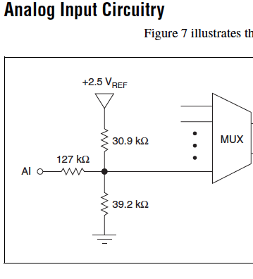
I am using the analog inputs NI USB-6008. The specification says they have a 144 k ohms input impedance. But it does not say what is the cut-off voltage. If you leave a disconnected and measure the voltage you will get 1.4 volts. So I guess it's the cut-off voltage, but it is not spec'd.
Someone agree that these Amnesty International isn't terminatied by 144 k - ohms to 1.4V? Is this in the documentation somewhere?
Figure 7 on page 16 of the NI USB-6008/6009 User Guide and specifications shows the strange input of this unit circuit.
Lynn
-
reading of the analog inputs with RPC
Hello
Because LabVIEW can not handle this (in VI; the value that you have saved the excel file has not been the same, that I saw during the measurement...) This confused me for a long time
 ), I want to write a C++ program (IDE: Dev - C++) which can read & record 2 analog inputs of the NI USB-6009 box. For this, I looked for an example of National Instruments and I found a little. But my problem is that I can't even use any example, because it has always held a mistake, after that I have compiled and started.
The error once the task has been created and has the :-200220 error number with the description "device identifier is invalid. But I do think that its invalid, because it's the xP example
I must say that I am new in programming C++, which means I could have a rookie mistake. And I couldn't find documentation or something for the NOR-DAQmx library.
Someone has similar problems with DAQmx and C++ and know how to fix? I don't really know what I can do now without a working example or documentations...
Hi Mario
It's the same thing. You didn't just save all of the data:
Please take a look at my comments in the attached VI.
Christian
-
What is the minimum response of analog input, through DSP online, output analog time?
Hello experts!
I want to know if it is possible to get a very quick response latency (~ 1 ms) sound recording (analog input), through online registration (DSP online), the presentation of his (analog output) processing, by using the DAQmx programming codes. My system of NEITHER includes NOR SMU 8135, SMU 6358 DAQ Multifunction controller and SMU 5412 arbitrary signal generator. I also have access to the latest version of Labview (2015 Version) software.
My project is on auditory disturbances, which inovles record vocalizations, manipulating the recorded vocalziations and then present the manipulated vocalizations. My current idea of how to achieve this fact triggered output voltage after reading the input using DAQmx Read samples. DAQmx Read output is filtered online and then passed as input for the DAQmx writing for analog output. For purposes of illustration, examples of code are presented below. Note for simplisity, codes for the trigger part are not presented here. It's something to work in the future.
My question here is If the idea above should be reaching ~ 1ms delay? Or I have to rely on a totally different programming module, the FPGA? I am very new to Labview so as to NEITHER. After reading some documentation on FPGA, I realized that my current hardware is unable to do so because I do not have the FPGA signals processing equipment. Am I wrong?
Something might be important to mention, I'm tasting with network (approximately 16 microphones) microphones at very high sampling rate (250 kHz), which is technically very high speed. Natually, these records must be saved on hard drive. Here again, a single microphone is shown.
I have two concerns that my current approach could achieve my goal.
First, for the DAQmx Read function in step 2, I put the samples to be read as 1/10 of the sampling frequency. It's recommended by Labview and so necessary to avoid buffer overflow when a smaller number is used. However, my concern here associated with the latency of the answer is that it might already cause a delay of 100 ms response, i.e. the time to collect these samples before reading. Is this true?
Secondly, every interaction while the loop takes at least a few tens of milliseconds (~ 30 ms). He is originally a State 30 late?
Hey, I've never used or familiar with the hardware you have. So I can't help you there.
On the side of RT, again once I don't know about your hardware, but I used NOR myRIO 1900, where he has a personality of high specific speed for the RT where I can acquire the kHz Audio @44 and process data. Based image processing is ultimately do the treatment on a wide range of audio data you have gathered through high sampling frequency and number number of samples as permitted by latency, please check this .
I lost about 2 weeks to understand host-side does not work and another 2 weeks to understand the even side of RT does not work for online processing (real time). Then, finally now I'm working on FPGA, where the sampling rate is 250 kHz (of course shared by multiple channels).
The complex thing with FPGA is coding, please check if the filter you want is given below as labview automatically generates some codes of some filters.
Most of them will work in 1 SCTL IE if your target has 40 MHz clock algorithm will run in 25 ns. That's what I was looking for, I hope you
See you soon... !


Maybe you are looking for
-
Where is the user interface to rearrange the search engines in Fx34?
I found the new page in the Options dialog box, but this does not seem to allow the reorganization. In addition, what happens if I want (or need) to see more than just the icons to tell apart search engines?
-
WiFi for computer laptop HP ENVY 15 and Ethernet connection problem
Hi, a few months ago, I brought a HP ENVY 15 Notebook PC running windows 8.1. It is connected to my wifi with Ralink RT3290 802.11bgn Wi - Fi adapter. My modem is a Technicolour TG582n 2 Wireless ADSL + with wireless 802.11 b/g/n compatible. As soon
-
Error 800b0100 during the installation of any windows update
Hello I have a problem running Vista updates. I can't update to SP1 via standalone as well. I am shown error 800b0100 all failures. I ran here is the log and system update readiness tool =================================Preparation of control system
-
Drivers for SM Bus controller and PCI Simple communication controller
Hello dear friends, PC model number is P6-2355IL I need two drivers. Please take a look 1 - SM Bus controller 2 PCI Simple Communications Controller I need them for windows XP Professional and windows 7 Ultimate Both 32 Bit 64 n Thanks to all in ADVA
-
F300 series open the printing preferences window
You can set the print preference setting window automatically opens on the 'Shortened' page, and if so how do you go?