Property names of waveform graph
I want to choose between the two types of axis on my x waveform table.
(1) absolute time---> time--> AM/PM and HH Custom Format: mm S
S
(2) IF the rating to 3 digits (digits precision) and hide the trailing zeros selected.
Anyone know the names of the properties of these attributes of map of waveform? I tried to look in the list which arise when you make a graphic waveform property node. But I could not find. I think I certainly lack.
BTW, I have 2 waveforms on the same list of waveform.
What you want, it's XScale.DisplayFormat.Format, XScale.DisplayFormat.Precision and Xscale.FormatString. To see the correct format strings, you can right click, select Xscale > set form and in the Properties window, select the Advanced Editing Mode.
Tags: NI Software
Similar Questions
-
I have a chart single 2D out a conditional of a loop indexing output such that over the rows of the table are not the same size. -Basically, they have different starting and ending points and sizes. -Not so concerned by the endpoints, because as soon as I get correctly starting points, everything shows fall in place.
The challenge is that when I try to have the variable t0 (start time) for each line, the wave of construction vi form would always keep each line at the same starting point.
I used the approach bundled with success (the cluster approach ensures that each waveform starts at different times according to the guidelines of my t0 defined for each line) but then I'm not able to get in the channel names I could make using the graphical approach (wave generation) waveform.
In essence what I get here, I'm losing here.
Because I don't want one of my mentors, Bob and Altenbach have fed up with me I have attached a vi this time

Attached VI shows a combination of the two attempts (first with the waveform graph) and then with the graph of cluster
1. with the first (graphical waveform), I get my channel names as you wish, but the alignment of the wave is not correct.
2. with the second (graphical cluster), the alignment is good, but I can't do the names of channel in the chart, even if they are present in the cluster.
I read some reviews that mentions that attributes can be displayed with waveform and data Dynamics (not clsuters) so I guess that's why.
I saw another report indicating the start time for a waveform 1 d will always remain the same for the rest lines defined for the first line even if changed for the following lines in a loop.
So I guess my question is: what is the way around questions like that?
First of all, let me be the first to the congratulate and thank you for finally posting a code! I'm not 100% certain I understand your question or your code, but I have an idea, perhaps, of what you want to do, so I wrote a little VI who made something simple that could be relevant.
You mention waveforms of different lengths and beginning at different times. You also want everyone to have a unique attribute (although I'm not sure what you want to do with the attribute). So, I did the following:
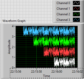
- Generated an array of 100-sample random to represent one second of a waveform.
- Created 4 waveforms on this 100-sample basis. The first waveform (channel 0) is just these 100 points. The second, 1 channel, is the concatenation of string 0 with the base of 100 samples, or a waveform "double". Channel 2 is 1 string concatenated with the base, and channel 3 is 2 string concatenated with the base.
- In order to trace the four channels that they rest 'on' the other, the waveform has the number of the channel added to it. Channel 3 is 3 + (4 copies of the basis of 100 points), a waveform 400-point random centered around a shift of 3.
- All channels have dt value 0.01 (but I guess I could have varied, as well).
- To make the channels start at different times, I started channel N N seconds before channel 0 (by subtracting the index of the loop, I, T0).
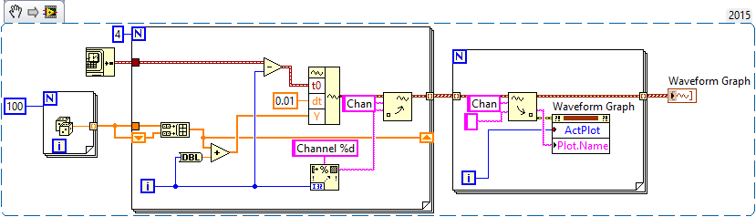
- For each channel, I created an attribute called "Chan" equal to "Channel N" (where N = 0, 1, 2 or 3, as the case may be).
This is the plot that results. Scale X is the absolute time value (no Date) using the 24-hour HH: mm
S format. You can see that the plots are 1, 2, 3 and 4 seconds of time, and are offset from each other by a second. I used the trace attributes to change the name to the respective attribute.The code to do this is very simple - I almost don't need to show it, because I think it is completely described by the text above, but this is here:
Now, it was not that much faster that some of your previous posts, when you refused to your postcode, "guess us" what you wanted (but not to not correctly guess), you tried to "push" us in the right direction (still refuses to post code), and no one seemed very happy?
Bob Schor
-
Change the axis label w.r.t. the scale automatically in the waveform graph
Hello
Is it possible to change category axis labels and the value the axis according to the scale automatically? I have a waveform graph which is automatically resized and values on the y-axis of milli, micro and nano volts according to the results of the output from the tests carried out. I need the label of the axis to change automatically according to the scale... Could someone tell me please how to do this. Thanks in advance.
Best regards
Julien
Alain,
I don't know exactly what you want.
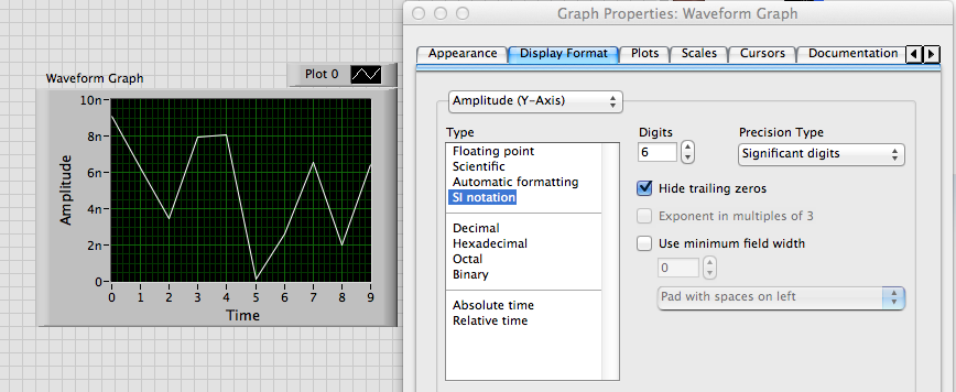
If you want to just scale to change as follows: 10n or 5u, use the property format scale IF the Notation.
If you want to change the name of scale label text, you use the YScale.NameLbl.Text property. The attached VI shows one way to do something like that.
Lynn
-
amplitude of the waveform graph
Hi guys,.
could you please tell me how to control the amplitude of a waveform graph. I want the mV amplitude, and I want to control the scale of numbers also.
Thank you
Bill David
Bill David,
You want to manually set all by developing the program or by running program?
For a manual start by turning off Autoscaling on axis Y. Then comes the value end upper and lower values you want.
Programmatically is similar except that you use property nodes. Some properties have names that might be a little confusing, you may need to do some exploration and trial. Context-sensitive help and help detailed will be your friends.
Lynn
-
How to get the individual history of the multiple waveform graph plot
I have a table of waveform with several plots, which is a cluster as input.
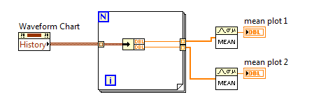
I want to calculate the average of each of these plots. With simple concession of waveform graph, all I had to do is to use the property in the history of the graph node and pass the history to the generation averaged vi. With the array of multiple locations, I am unable to get the history of each parcel.
The property of the history of the land multi card node is an array of custers, not quite what I need to calculate the average.
How to me history of individual plots?
Thank you.
unbundle just your datapoints inside a loop like this
-
Two background colors for the same waveform graph
Hello guys!
I have a question for you: I am a new user of labview, so please be nice!
So here's the deal: I just created a thanks 4 thermocouple temperature registration program.
In real time, I then have a waveform graph 4 curves as soon as I start my program. And in my program, I had a button that allows me to record the temperature in a file for a period of time at a certain frequency.
So, what I have is: I got my chart of waveform with a black background for example, and once I pressed the button, the background color will be changed automatically to highlight the part of the graph where the record occurs, then the background will return to the black after finished recording. In this way, on the same graph, I could say that registration took place from here to there by looking at the graph. I have two different background on the same graph.
I don't know how to change the background of a chart using the property node, but is it possible to do what I want?
I hope I'm clear. Otherwise, feel free to ask me for more details... I might post my vi if necessary
See you soon
Well, I know this is not exactly what you want to do, but you can try the following.
Change the color of the line on the chart when recording occurs.
You could therefore have a red line, then press on save, then it turns blue, then back to red.
And when that is confusing since you have 4 different lines on the chart 1,
You can change to a red line and a dotted red line, for example.
Would that be acceptable? If so, I can show you how to do this.
-
switch between log and linear waveform graph
I have a waveform graph that plots linearly. However, it causes an error during the logarithmic line tracing. Is anyway to create a switch that allows me to change between log and linear plot without creating additional graph?
Thank you
Chris
Use a property node: Y Scale.Mapping Mode. Written 1 to the node passes in logarithmic mode and 0 is for the linear.
Lynn
-
Hello to you all, useful forum fans! :-)
I implements an array of tape showing the values of several parameters in real time, using a waveform graph, but during the race he keeps resetting of the history of the card at irregular intervals. Unfortunately, because it is for my work, I can't post the code. I'll do my best to describe the problem and the installation program, however.
I have a data acquisition loop to read the values in real-time in a table of the floats and stores it in a global variable functional memory data buffer that contains a table 2D of floats, a 'page' of floats by time interval. This forum works at 50 Hz through the expectation of millisecond Schedule VI.
I then a chart update the loop running at 10 Hz via forward schedule VI. This loop reads the data of all samples buffer VI he has accumulated (usually 5, but sometimes 4 or 6) and converts it to an array of waveforms through the VI of waveform build by taking each column of data and by assigning to it, definition dt to 0.02 (50 Hz), and parameter t0 to time less dt current multiplied by the number of samples in the table. The terminal waveform graph is then set to this table of waveforms.
Most of the time that it works well, with the new values added the previous values to create a smooth graph of multiple plots with the correct values are displayed. However, sporadically the chart Flash empty and begin to fill again from scratch. I can tell is just jump in time (the axis of abscissa) because I can move the axis scroll bar and there is no other data to scroll.
I in addition to these two loop loops a GUI-structure of the event and a task of State machine loop. However, I have excluded these two loops ownership history of the graph through inspection and breakpoints. This is why I can only think that there are conditions or the type of data which, once introduced in terminal results of the graph by adding DO NOT present data as usual. Empty array is not the answer; I tested with a separate simple test VI, and therefore in the chart, keeping the currently displayed data but do not update new data.
I would appreciate any idea what any of you have as to the possible causes of this behavior. I apologize again for not being able to view the actual code, although I can work to establish a similar setup with the data buffer, etc. in a separate VI and after that. Also, I would like to know if you want me to describe the other logic, settings, or the circumstances for you.
Thank you very much for your help!
-Joe
Whenever I've seen this problem when you use a waveform he chart endded up being a problem with;
(1) the number of parcels has changed.
(2) the names of the plot has changed (WF attribute).
(3) time info Goffy where t0 and dt were inconsistent with what was already posted (new data point a t0 that is earlier than what is already plotted this plot)
It's a pain to figure out the first time.
Ben
-
horizontal line on waveform graph
Hello world!
I'm still new to Labview, but I am trying to add a horizontal line to a already established "histogram" on my graph of the waveform. How this code works is that it takes a force of a forceplate (this force Exchange) and trace it as a bar to the left of the graph target (it's their strength of target - height represents the amount of force they wish to exercise). Ideally, you would like these bars have the same height (the person exerting the force uses the same amount as their target). To make it a little easier for them to see the target height, I'm wanting to draw a horizontal line at the height of the target, but keep the bar chart so that they can see how far their strength exercised power comes from their target they grow stronger or softer. Is there an easy way to do this? Ideally I'd like the bar chart and line, but if there must be two lines (one for the target does not move and one for the force that would change) which is very good also.
Thank you for your advice and your entries!
Emily
Dear emmaline35,
you use a waveform graph, not a graphic. Graphic does not markers (which would be the most simple solution to mark the extreme).
There is a suggestion that I have not tried: http://lavag.org/topic/11199-adding-a-reference-line-to-a-waveform-chart/?p=67119 (some solitions partially work are suggested earlier in the thread, too)
Suggestion 2) If you need this marker (horizontal) and if your application is not computationally intensive (which does not seem so), I would use a chart and add a horizontal guide. That can be set programmatically: property node > XScale > [MarkerValues] but you will have to replot the graph for each newly received value.
See you soon,.
-
How to connect a cluster of berries to a waveform graph
I'm trying to reproduce the pattern-block which is attached to this issue, but I don't know how I connect the waveform to my clusters of berries. I get an error that "the type of the source is table 1 d of cluster of 2 elements. The sink type is 1 d doubles [64-bit real (precision ~ 15 digits)].
You need a chart xy, not a waveform graph.
(Remember also that this table index is resizable. You only have a single instance. Your photo code is old, ~ LabVIEW 4.0 or MORE)
-
missing samples in the waveform graph
Hello world
When processing a file .wav into pieces, I noticed that there are missing samples on the waveform graph where two pieces must be met for the display. What could be the cause of this? Any help appreciated. Thank you!
Milan
Your method of reading in pieces in a for loop is create a table 1 d of waveforms with the tunnels of automatic indexation. It is as well as what you have the data appear in different plots. I don't know if that's what you want.
But if this is the case, the problem is that you get to the last point of the first plot, and the first point of the next parcel is a different value. Because they are two different plots that you do not get the line to join them, as you do between points that are part of the same plot.
-
Save the Studio measure waveform graph as a file for reading later
Hello
I would like to know if there is an easier way to record data are rendered on a waveform graph (configured as a graphic of the band) to capture incoming data in the code and send copies of it to a file. It would be nice if there was a method to do this, with all relevant metadata stored in the file (color, etc.). Better yet, the file could then be opened in a labview application (for example, a TDMS file) for later review.
Thank you.
PS. I use VS2010 and MS 2010.
So, it looks like you already have all the data points. For metadata that you mentioned, line color, plot colors, point colors, line styles, etc. are all accessible from the properties so if you wish, you can retrieve all that data.
I think that upon return from t0 is the same compensation history, you can use the ClearData() method.
-
Sort the Datafinder results by property name
Hi all
I want to sort my resultlist property.name = "BENCH":
Dim oMyDataFinder, oMyQuery, MyDate, MyMin, oMyResults
Set oMyDataFinder = Navigator.ConnectDataFinder ("My DataFinder")
If oMyDataFinder.Name = "My DataFinder" Then
Dim AdvancedQuery
Set AdvancedQuery = Navigator.CreateQuery (eAdvancedQuery)
AdvancedQuery.ReturnType = eSearchFile
Call AdvancedQuery.Conditions.Add (eSearchFile, "BENCH", "is", "*")
oMyDataFinder.Search (AdvancedQuery)
Set oMyResults = oMyDataFinder.Results
error resume next
Call oMyResults.Elements.Sort ("BENCH", FALSE)
MsgBox (err.number & "" & err.description)end if
the error is ' 438 Proprietà o Método supportati not dall'oggetto ".
oMyResults.Elements.count is 1
What is the problem?
can I sort by date (the "DatatypeDate" property type)?
Thank you
Yustas
Hello Yustas,
your variable 'oMyResults' is already a collection of items, so there is no a member of elements.
Try to use instead:
Call oMyResults.Sort ("BENCH", FALSE)
Hope that helps,
Eva
-
Hello
I use the metal theme to design a façade of Labview. I would like to plot x, y of the data on a chart, however, there is only a graphic of waveform and waveform Graph available in the metallic theme. Can you help me in tracing the x, the data is in the curve of waveform in the attached VI?
Thank you
hiNi.
You can customize the graph of the metallic wave and replace it with a XY Chart and set some properties to match the waveform graph
Or let me do it for you
Joint back-saved for 2011
Cross posted at the "Discussion of UI military theme" on the side of the community
-
Hello
I have a question about the waveform graph. My prolbem is that the x-axis of graphic waveform shows only up to x = 0.1 and it does not show the chart more than that, and when I increase the X-AXIS scale in his PROPERTIS (lets say at x = 2), increase the Max on the x-axis (x = 2) but the chart presented to the 0.1! I have attached a very simple code that shows my problem.
Could you help me please? I need the graphics to show me for all values x, x = 0 to x = 10.5.
Thank you
Soran
Hi Soran,
Sorry, your question is still not clear to me.
You hear all the values up to 10? I kept freq = 0.1 and adjusted other values, don't know if that's what you are pregnant.
Maybe you are looking for
-
Thunderbird, says my ISP does ' t recognize my password, no e-mail
No e-mail. T - bird said that my ISP does not recognize my password. Worked fine until today. I went on the Web site of my ISP (Mediacom)and the password got me right in. But it does not always work with the T-bird... ???
-
POLICE MAIL ENTERING TOO SMALL
WHEN I GET AN INCOMING EMAIL, THE MESSAGE IS ALMOST TOO SMALL TO READ. I WENT TO VIEW-ZOOM-TEXT ONLY ZOOM IN. I DO THIS A COUPLE OF TIMES AND I CAN READ IT, BUT THE REST OF THE TEXT BECOMES TOO LARGE. WHEN I FINISHED READING, SO I UNDO WHAT I DID.
-
My friends Cpu to turn on/off the system makes throgh POST on the display of the MESSAGE and then hangs on the PCI Device Listing... Verifying DMI Pool Data... It's on a P4 Socket 470 850 Chipset, RDRAM, WD 120 GHz HD, McAffe Anti-vires, 350W Pwr Sup
-
I have about 1000 vacation photos and all are 3.23 mb (4608 x 3456).
I want to compress them using MS photo mgr. I don't want compromising pictures, but I'm sure by doing this, I share them? I see that I can compress for web pages, these will be posted on my blog. I hesitated because I'm not sure what it actually doe
-
Errors of registry and junk files
I analyzed my pc and it tells me I have errors of registry and junk files? How can I fix it?