Pull graphics individual of a multiple waveform graph?
Hi all, is there a way to the analysis of individual graphics of a waveform based on a description given? I know that the wave doesn't than the Y, t0 and attributes t, but there must be a way to do this.
The user enters a group of data by channel. I want to be able to do is isolate one graph of the waveform based on the tag name of the channel and show this on a separate chart.
I've attached screenshots taken from view of the code where the plots are generated and the center of user input.
I would appreciate help. Thank you!
LabVIEW 2012
Windows 7 64 bit
Hello
You can do it. When you get the name of the attribute (as in my first attachment), you can compare it with the name of the desired tag, using the functions in the range of comparison.
If your match is found, then a case structure and write the waveform in a chart.
Otherwise, proceed to the waveform through a shift register and write in the graph.
I have attached a VI in LV 2010.
Tags: NI Software
Similar Questions
-
How to get the individual history of the multiple waveform graph plot
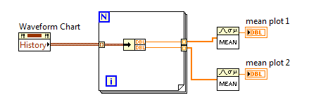
I have a table of waveform with several plots, which is a cluster as input.
I want to calculate the average of each of these plots. With simple concession of waveform graph, all I had to do is to use the property in the history of the graph node and pass the history to the generation averaged vi. With the array of multiple locations, I am unable to get the history of each parcel.
The property of the history of the land multi card node is an array of custers, not quite what I need to calculate the average.
How to me history of individual plots?
Thank you.
unbundle just your datapoints inside a loop like this
-
Multiple waveform graph, history of waveform card
Hello to all my colleagues.
I have problem with software of my purchase. I create software for the acquisition of 40 signals. I need to view and save these signals. I measure these signals with different frequencies (this depends on the user's selection), but the lowest frequency is 500 Hz and the highest is 2 000 Hz. Because I see a different size of X scale (5 sec - 60 dry), I decimate these signals for display and display only 100 samples per second.
I think that my problem is related to a very long history of waveform graph. When I display all signals in a single diagram, permanently signals are not displayed and the table is larger than the correct size of X-scale, means that the courses of the waveform graph freeze. I think the problem is connected only with display and no acquisition because I tried to check the measured data and there isn't any problem.
You have one any opinion how can I solve my problem?
Please, help me, because I'm out of ideas.
Thak you.
Here's my VI.
Double post,
Please find the thread here:
http://forums.NI.com/T5/LabVIEW/multiple-waveform-chart-history-of-waveform-charts/m-p/1762160
Best regards:
Tamas Szekely
Technical sales engineer
-
Multiple waveform graphs do not simultaneously view data
Hello
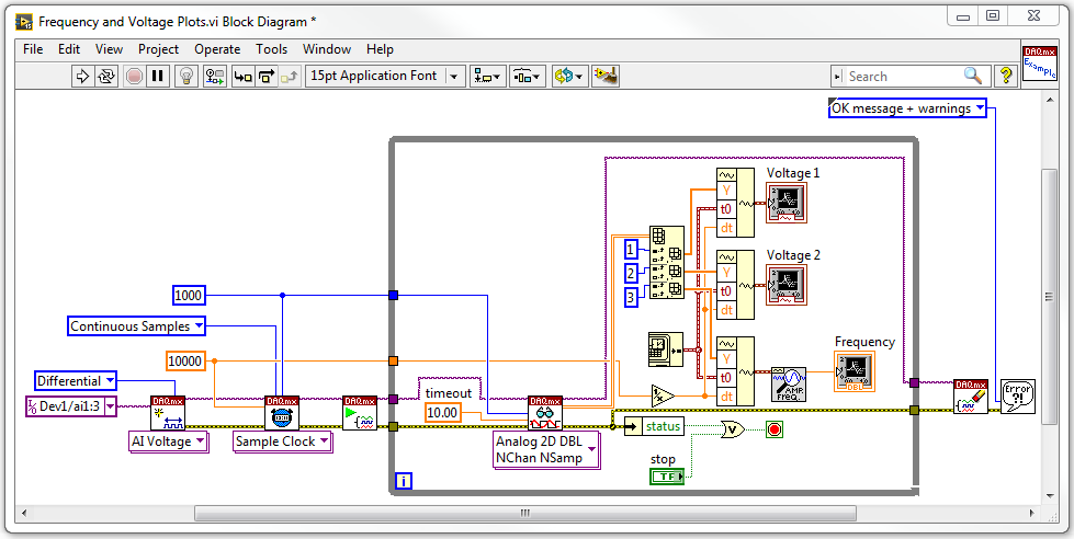
I use a box USB-6009 to acquire three analog input voltage signals simultaneously. I want two plot the voltage wrt time signals, while the third signal, I want to extract the frequency and then draw the wrt time frequency. I want the three of us graphic waveform having a category axis in units of seconds from zero seconds. My diagram of block VI is below:
When I run the VI, I get some problems. First, the frequency table is not plotted all the data, and although I am happy, time begins and reset it's count in tenths of seconds rather than in seconds.
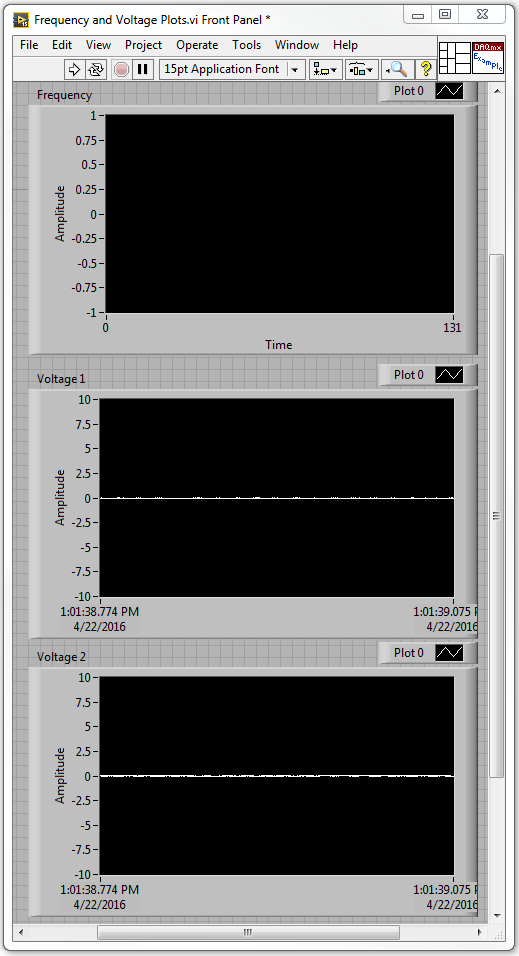
With the voltage 1 and 2 maps, the voltage is read correctly, but the x axis are in terms of date and instead of seconds. The front of the VI is below:
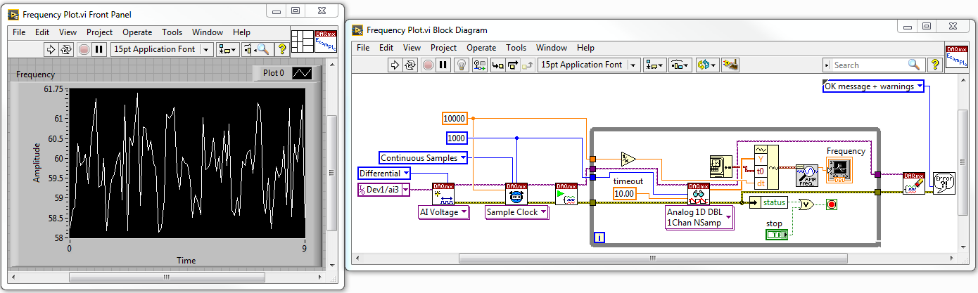
I tried to run the VI with only the third signal voltage being played and the table of wave shape of the plots the frequency perfectly. The Panel diagram and the block before lower is to:
Could someone tell what I'm doing wrong in the first VI?
1. you must use the version of waveform table Mutiple multi-channel DAQmx Read Points. Then, you don't have to accumulate the waveforms yourself.
2 tables index is 0-based. Thus, the filrst of the table element is actually 0, not 1.
-
Create multiple vertical lines for waveform graph
Hi all
I use NI 9234 USB vibration of rotating machinery data acquisition. A simple VI was made for this.
The next step is the analysis, signals were well displayed waveform, time, FFT, all important values... and so on.
But I have a problem with multi vertical lines of the waveform graphs, it looks very simple, and I tried many ways but have yet to get it with a good solution.
Vertical lines are used to display the frequency of breakdowns of machines (such as we post 1 X, 2 X, 3 X,... more harmonics).
Does anyone have a solution for this problem?
Thank you very much!!!
Here's a very quick example (LabVIEW 8.2)
-
Save the Studio measure waveform graph as a file for reading later
Hello
I would like to know if there is an easier way to record data are rendered on a waveform graph (configured as a graphic of the band) to capture incoming data in the code and send copies of it to a file. It would be nice if there was a method to do this, with all relevant metadata stored in the file (color, etc.). Better yet, the file could then be opened in a labview application (for example, a TDMS file) for later review.
Thank you.
PS. I use VS2010 and MS 2010.
So, it looks like you already have all the data points. For metadata that you mentioned, line color, plot colors, point colors, line styles, etc. are all accessible from the properties so if you wish, you can retrieve all that data.
I think that upon return from t0 is the same compensation history, you can use the ClearData() method.
-
Hello
I use the metal theme to design a façade of Labview. I would like to plot x, y of the data on a chart, however, there is only a graphic of waveform and waveform Graph available in the metallic theme. Can you help me in tracing the x, the data is in the curve of waveform in the attached VI?
Thank you
hiNi.
You can customize the graph of the metallic wave and replace it with a XY Chart and set some properties to match the waveform graph
Or let me do it for you
Joint back-saved for 2011
Cross posted at the "Discussion of UI military theme" on the side of the community
-
Hello
I have a question about the waveform graph. My prolbem is that the x-axis of graphic waveform shows only up to x = 0.1 and it does not show the chart more than that, and when I increase the X-AXIS scale in his PROPERTIS (lets say at x = 2), increase the Max on the x-axis (x = 2) but the chart presented to the 0.1! I have attached a very simple code that shows my problem.
Could you help me please? I need the graphics to show me for all values x, x = 0 to x = 10.5.
Thank you
Soran
Hi Soran,
Sorry, your question is still not clear to me.
You hear all the values up to 10? I kept freq = 0.1 and adjusted other values, don't know if that's what you are pregnant.
-
How to display the signal on a waveform graph in Labview Signal Express?
Hello
I want to display a signal in Signal Express 3.0 in a "waveform table", but don't know how to do it and I think that it may be impossible?
In Labview, there are two ways to view data, a 'waveform table' or a 'waveform graph. The great thing with 'picture of waveform' is that it allows you to set a length of history and you can see the data move to the left (option graphic strip) that samples are recovered. It works perfectly.
In Signal Express I can only select "Graph XY" or "Waveform curve" by doing a right-click of the mouse, but I can't select "table of waveform. Is it really true that it is not possible to view data in a graph of waveform "with Labview? (1 analog signal during streaming, 100 samples to read at the rate of 1 K)
Thank you in advance,
Enrique
Hi Enrique.
You are right that there is currently no graphic waveform in SignalExpress. The thing nearest you can join, is saved data under a log and then he looks one when recording (which I know this isn't quite the same interactive behavior).
For your last comment, you wrote 'waveform curve', but I guess you meant 'picture' here as well.
Sorry about that. We recently received this request, then perhaps in a future version.
Phil
-
Is there anyway to rotate a waveform graph, so that I can view them vertically? (the wave moves vertically, rather than left to right)
You vote for this idea on the exchange of ideas, swap axis allow for graphics signals and diagrams intensity (and possibly others)
-
How to display more than two waveforms on a waveform graph?
Well, I have a question in the basics of waveform graphs. I have to post four waveforms simultaneously in my program. I can see two graphs on it, but when I try to display four waveforms, I get an error:
You have two or more data types of cluster wired together, but clusters have different types or numbers of items.
Cluster (unnamed), a group of 3 elements.
conflicts with graphic waveform cluster, a cluster of 2 elements.Is there anyway that I can change a graphic in waveform to a cluster of 4 elements? Because I borrowed this waveform of a VI example on waveform cards "Charts.vi", so I guess it must have been programmed to be a cluster of 2 elements.
I hope that I have my question clearly.
Thanks in advance
One of the problems that you have is that data from the DAQ assistant has a time stamp from now which is about 3 billion seconds
Data from the simulated signals has a time stamp based on the beginning of the acquisition which is about 0 seconds.
So, the table needs to be stretched early in LabVIEW time now to show all the data.
Change signals simulated so that the timestamp is the result of an absolute time, then you should be able to see all the signals.
-
Hello to you all, useful forum fans! :-)
I implements an array of tape showing the values of several parameters in real time, using a waveform graph, but during the race he keeps resetting of the history of the card at irregular intervals. Unfortunately, because it is for my work, I can't post the code. I'll do my best to describe the problem and the installation program, however.
I have a data acquisition loop to read the values in real-time in a table of the floats and stores it in a global variable functional memory data buffer that contains a table 2D of floats, a 'page' of floats by time interval. This forum works at 50 Hz through the expectation of millisecond Schedule VI.
I then a chart update the loop running at 10 Hz via forward schedule VI. This loop reads the data of all samples buffer VI he has accumulated (usually 5, but sometimes 4 or 6) and converts it to an array of waveforms through the VI of waveform build by taking each column of data and by assigning to it, definition dt to 0.02 (50 Hz), and parameter t0 to time less dt current multiplied by the number of samples in the table. The terminal waveform graph is then set to this table of waveforms.
Most of the time that it works well, with the new values added the previous values to create a smooth graph of multiple plots with the correct values are displayed. However, sporadically the chart Flash empty and begin to fill again from scratch. I can tell is just jump in time (the axis of abscissa) because I can move the axis scroll bar and there is no other data to scroll.
I in addition to these two loop loops a GUI-structure of the event and a task of State machine loop. However, I have excluded these two loops ownership history of the graph through inspection and breakpoints. This is why I can only think that there are conditions or the type of data which, once introduced in terminal results of the graph by adding DO NOT present data as usual. Empty array is not the answer; I tested with a separate simple test VI, and therefore in the chart, keeping the currently displayed data but do not update new data.
I would appreciate any idea what any of you have as to the possible causes of this behavior. I apologize again for not being able to view the actual code, although I can work to establish a similar setup with the data buffer, etc. in a separate VI and after that. Also, I would like to know if you want me to describe the other logic, settings, or the circumstances for you.
Thank you very much for your help!
-Joe
Whenever I've seen this problem when you use a waveform he chart endded up being a problem with;
(1) the number of parcels has changed.
(2) the names of the plot has changed (WF attribute).
(3) time info Goffy where t0 and dt were inconsistent with what was already posted (new data point a t0 that is earlier than what is already plotted this plot)
It's a pain to figure out the first time.
Ben
-
How can I display only a part of the scale in the waveform graph
This is the first time I try to use the waveform graph, since now, I used the table of waveform.
The reason why I moved to the chart, it's that I need cursors.I have 2 problem
the first: in the diagram, the graph moves when I add a new data and the scale of the x-axis stay the same size, in the right size I always saw the new data. How can I do that with waveform graph?
Second: How do I say Labview to the day I click on the graph, I need that because when move graphic I lose the day, and to make I need to zoom out, I drag the imprecateurs.
All this must be done programmatically. The LabVIEW graphic accepts tabular data, not only as the table and the graph doesn't have the ability to retain the previous points, like the story of a graph. You will need to retain previous values and then continually update the graph with the old and new values to get a shift register "chart as behavior. Cursors should be written programmatically re of each iteration, since you rewrite the entire graph.
-
you use an image behind the waveform graph?
Well guys, I want to know if its possible in LabVIEW.
I know I can put an image predefined waveform graph so still when I run my program I see that image.
But now I want to use a picture inside the graphical waveform... like a logo or something related.
Is it possible? If so, how can I do that?
Thank you
How about you, making the transparent graphic background and put the image you want behind it?
-
horizontal line on waveform graph
Hello world!
I'm still new to Labview, but I am trying to add a horizontal line to a already established "histogram" on my graph of the waveform. How this code works is that it takes a force of a forceplate (this force Exchange) and trace it as a bar to the left of the graph target (it's their strength of target - height represents the amount of force they wish to exercise). Ideally, you would like these bars have the same height (the person exerting the force uses the same amount as their target). To make it a little easier for them to see the target height, I'm wanting to draw a horizontal line at the height of the target, but keep the bar chart so that they can see how far their strength exercised power comes from their target they grow stronger or softer. Is there an easy way to do this? Ideally I'd like the bar chart and line, but if there must be two lines (one for the target does not move and one for the force that would change) which is very good also.
Thank you for your advice and your entries!
Emily
Dear emmaline35,
you use a waveform graph, not a graphic. Graphic does not markers (which would be the most simple solution to mark the extreme).
There is a suggestion that I have not tried: http://lavag.org/topic/11199-adding-a-reference-line-to-a-waveform-chart/?p=67119 (some solitions partially work are suggested earlier in the thread, too)
Suggestion 2) If you need this marker (horizontal) and if your application is not computationally intensive (which does not seem so), I would use a chart and add a horizontal guide. That can be set programmatically: property node > XScale > [MarkerValues] but you will have to replot the graph for each newly received value.
See you soon,.
Maybe you are looking for
-
Why firefox saves to the temp dir even if I put to download dir
I even tried to turn suggests saving dir when recording, but firefox saves directly to the temp dir c file always...
-
New hard drive does not appear in the disk utility
I am installing a new hard drive in my late 2011 13 "MacBook Pro. I started using apple's online retrieval system and went to disk utility. I tried to format the drive, but he is stuck saying "remove disc" for about a half hour, and then I had a rota
-
PXI-1042 q with controller 8331
HI........ I want to configure a single chassis PXI-1042 q with controller PXI-8331. I have connected 2 I\O Digital Digital card (PXI-6515) and 1 card(PXI-6514) I\O to this chassis. And I have connected this chassis to my PC with the serial cable (OR
-
How can I remove a Proxy XD to my computer? http://static.AK.fbcdn.NET/connect/xd_proxy.php
-
My delete button does not work in Outlook Express I can not delete emails!
My delete button has stopped working in Outlook Express! I can delete is no longer emails-how fix this?