Pulse frequency of CO generates actually 1 pulse per second?
Hi all
I have a VI installed outside in the attachment below. I seem to have a lack of understanding on how to program this VI here. I do not understand what might not.
The VI is very basic. The frequency has been set to 1, and the units are Hertz. For me, this means that the application must send a pulse to my linear actuator ONCE per second. I have a simple Pulse counter set up in VI so count the number of pulses is actually sent (using the DAQ assistant). Why is that when I run the program, I get around 300 pulses per second? Elevate the value makes it goes a little faster, but the value isn't really do go more slowly. It seems no real correlation between the input frequency and the number of pulses that are sent.
I just want a program that I can enter "1 pulse per second" or however many impulses I want per second and have the card send a pulse per second (or however much is entered). Where should I start? I have an entire program written and ready to go, but this concept of base here escapes me completely.
Thank you
James
Attached: photo 1) of the concept that I am completely baffled on 2) VI of my program that says the concept is used in
In the simple image, you run a loop as soon as possible (it has no timer mechanism). Inside this loop, you configure the task of the pulse, run it, then immediately stop and disable. You need to create the channel and configure the synchronization outside the while loop before it starts, and you need to clear the task outside of the loop this way, after the while loop ends. Depending on what you want to do, you should be able to move the beginning of the task outside of the loop this way, or simply let the task automatic start.
You will need to restructure your VI a little. I can't tell if you want to delete the task after each step, or simply change the frequency. If it is just the frequency, you can use DAQmx write to change; If you need start and stop the task, you will need logic to do once whenever you want to start (you can get an error if you start a task that is already running). There is no need of "Is the task performed?" since you do not use the exit for what it is.
EDIT: Also, it's always a good idea to put a waiting inside loops that run indefinitely. Otherwise, they will turn as soon as possible, all processors available time and prevent any other code to run. If you configure your task to meter correctly the time loop will not affect the value of the pulse (because it is done in hardware), but there is no need to run the quick loop.
Tags: NI Software
Similar Questions
-
How to generate two pulses per cycle? PCI-6251/6255
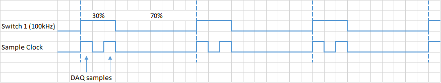
Hello. I want to generate two or more pulses per cycle like the timming diagram. This pulse will be used to trigger the sampling data.
I am ussing the PCI-6251. The VI examples to counter outputs can easily generate the first line, but the second I have no idea. All information can help.
Another problem could be the synchronization of this lines and data acquisition.
Concerning
Ivan C.
I would like to use the digital outputs for this - just generate a continuous at 1 MHz clock using one of the counters and write the following in your digital output lines:
H H H L L L L L L L
H L H L L L L L L L
If you want to use these signals to pick a different spot on the 625 x, you the output of wire in a PFI lines.
Best regards
-
Is the annual contract at $ 49.99 / month all billed in advance or actually $49.99 per month during the year?
Always a monthly payment via Adobe comes to a monthly contract or 12 months.
The only way to get paid in advance is through dealers such as Amazon.
http://www.Amazon.com/Adobe-Creative-membership-pre-paid-product/DP/B007W7A1OY
-
6602 synchronized with a different number of pulses per channel pulse generation
Hello
I try to use counters NI 6602 to generate 4 pulse trains that begin together but then proceed with each counter producing its own number of pulses (over mode) with its own frequency.
It seems that each of the 4 channels of wiring at the same special teams each channel to produce the same number of pulses based, apparently, on which channel was recently with the specified NumPulses value so that it is the (implicit) VI DAQMx Timing.
I tried to use separate tasks for each channel, but it seems that the there is much more uncertainty in the initial start of the train of impulses on each channel: unique task ~ 13us (coherent) delay between channels, a task for each channel (variable)... Although I'm not entirely confident in these temporal measures (estimates of the oscilloscope) +-15us. So it seems I'm sacrificing some synchronization to produce a different number of impulses for each channel?
Is it true, or is there another way to match the beginning of the independent pulse trains.
Vadim
You should be able to synchronize the start of 4 separate meter output tasks by having all the
looking for a common startup trigger signal. You can easily do yourself the trigger signal on
(for example) PFI_0 using a digital task rocking DIO_0.
-Kevin P
-
Data time stamp generated without fractions of a second.
Hello
I do some testing with redefining online timestamp column.
When you try to generate timestamp data looks like fractions of a second are 0s
When I insert:insert into t select r , systimestamp+ 1+r/(24*60*60*2) from (select rownum r from dual connect by level <= 100); select * from t where rownum <= 3; ID DATA ----- ------------------------------------ 1 15-MAY-10 01.59.16.000000 PM 2 15-MAY-10 01.59.16.000000 PM 3 15-MAY-10 01.59.17.000000 PM
That's ok.insert into t (101, timestamp '2010-01-11 11:11:11.123456');
What's wrong with my data generator? :))
Kind regards.
GregHello
user10388717 wrote:
HelloI do some testing with redefining online timestamp column.
When you try to generate timestamp data looks like fractions of a second are 0sinsert into t select r , systimestamp+ 1+r/(24*60*60*2) from (select rownum r from dual connect by level <= 100); select * from t where rownum <= 3; ID DATA ----- ------------------------------------ 1 15-MAY-10 01.59.16.000000 PM 2 15-MAY-10 01.59.16.000000 PM 3 15-MAY-10 01.59.17.000000 PMWhen I insert:
insert into t (101, timestamp '2010-01-11 11:11:11.123456');That's ok.
What's wrong with my data generator? :))
Kind regards.
GregArithmetic, such as dates
x + 1+r/(24*60*60*2)Suppose x is a DATE, not a TIMESTAMP and returns a DATE.
If x is a TIMESTAMP (as in your case), the system converts implicitly to a DATE, lose the fraction of a second.
Similarly, when you INSERT into your table, the system waits a TIMESTAMP, but if you pass it a DATE (as you do) the system implicitly converts a TIMESTAMP.Don't use no arithmetic dates with the TIMESTAMPS. There are other ways (although less convenient) to manipulate the timestamps.
For exampleSYSTIMESTAMP + NUMTODSINVERVAL ( (1+r/(24*60*60*2)) , 'DAY' ) -
What fsx actually require as much as the frame per second rate?
With higher settings, I show that it is running only 20-30 fps. I thought it would be more. My system can handle more.
------------------
-
square pulse time rather than the sampling frequency and size dependent frequency
Anyone know if it is possible to create a pulse square with its dependent on the frequency at the time rather than the sampling frequency and size?
for example if I set the frequency to 10. That means 10 pulses per second.
rather than having to set the sampling rate and use the equation
frequency = [(# of cycles) * (sampling frequency)] / sample size
Thanks in advance. a photo of the block diagram would be grateful if possible
NVM, that I solved it

-
Analog pulse of a photon multiplier tube
Hello
I am trying to establish if it is possible to count random negative analog impulses of a tube of multiplier of photon (PMT) with multifunction data acquisition OR or boards of counters/timers?
First of all, the properties of the PMT output are as follows (single photon response):
- 1.5 ns FWHM
- -50 mV to 400mv (random because of the amplification process in the PMT)
- Up to 5 million pulses per second (higher cause the overload sensor) who arrive at random times.
I would like to do is make the counting of simple events or events buffered count.
All counters seem to only be able to count digital TTL pulses. In this case, I have some electronics in mind which will convert the pulse the pulse of positive 5V CMOS logic (which, according to this site, is suitable for counter inputs) external signal conditioning. It also contains a dicriminator circuit to ignore the pulse below a threshold. With this signal, I intend to send to a meter entry NI USB Multifunction DAQ BNC for counting of events event / buffered.
However, in the hope to reduce the cost of my system, I was hoping it could be a way to define an analog trigger to create a pulse TTL of one of the of cards OR, therefore quite dodge the need for external signal conditioning?
Any help would be welcome.
Kind regards
Sean
You may need to strech the pulse to meet the minimum of the input of the meter.
I know you want to do without extra signal conditioning... However, we are building a signalconditioner to our task with a comparator MAX961ESA provided... 5V-driven layout is in the technical sheet

As a simple pulse strecher, I would try a simple low-pass RC before the entry comparer.
-
Hi, I want to use three USRP to communicate with each other. But I met the question of frequency offset. To eliminate the frequency, first of all, I want to use the external clock
to synchornize three USRP. I know I should use REF in the Port, but I want to use PPS to?. In addition, there good ideas to reduce the frequency shift? I'm a newbie to USRP, answer you will be highly appreciated.
Hi llg9012,
There are 2 ways to synchronize your USRP. If you have only 2 USRPs, you can use a cable MIMO to share the reference clock and clock PPS between the 2. Since you have more than 2 USRPs, you will need to provide a reference clock (10 MHz) and a PPS (pulse per second) clock all 3 units. After you have plugged them in this way, you will have to use a property node to set the reference clock source and the time base clock source (which is the clock PPS) external.
Sharing these clocks will keep the relative phase between all 3 constant signals. However, whenever you stop and start the device phase differences will not be the same. If you are only concerned that your frequency and phase without drifting through time, using external clock sources is the best solution. If you need your USRPs 3 to have the same phase, you can use a sequence of training to align the phases. There are posted examples here the community that can be useful for your work request:
https://decibel.NI.com/content/groups/NI-USRP-example-LabVIEW-vis?view=documents
Discover the angle of arrival detection and 6 x 6 examples MIMO to see some examples of how others are synchronize their USRPs.
-
DAQmx task Read DAQmx with sampling frequency of 10 Hz produced much too much data
I have a simple configuration with a strain of channel 4 OR-9237 amp holds a carrier of series C of WLS - 9163 (wired ethernet mode) - Details probably does not matter.
I used MAX to create a DAQmx task associated with which all four gauges samples. The calendar setting is "Scan Loads" is continuous sampling, 2 k buffer (read samples) and 10 Hz rate. I guess that this task would generate 40 data values per second - 10 for each channel.
I have a simple loop of reading using DAQmx Read.vi that works always (without any stimulation time). Playback is set to read all available data and then pump it into a table.
In the attached example, I also added a few words of debugging to stop the loop after N iterations.As the loop is programmed with a 0.2 second period, I expect each pass of the loop to read about 8 samples or 2 samples per sensor. Instead, I get hundreds each passage. It's like reading has substituted the sampling frequency specified in the task of the unit. I absolutely need data to be material to the rhythm.
Where have I lost?
Thanks Adnan,
I changed your example I selected 'Strain gage' entry analog and then lowered the minimum and maximum thresholds to +-1-2. What happens is that each other in the loop, I 2048 samples or zero samples. The display flashes a whole line and then it clears any other past.
In response to your second post, I understand that the loop cannot run quite right that I select. I think that, but at a sampling frequency of 10 Hz, I have to sleep on the software side for nearly a minute before I built 2 K samples.
I played with the frequency of sampling, assigning to various values from 0.1 to 10000Hz. The behavior is the same until I approach the high rates where available samples remains to 2048-4096 sometimes, the display becomes continuous.
Ahhh, Darn. Yet another search was this link that points to the root of my confusion. The 9237 can taste arbitrary rates using its internal clock. Duoh! I wish that the pilots are smart enough to warn you if there is a discrepancy between the selected sampling rate and capabilities of the device
-
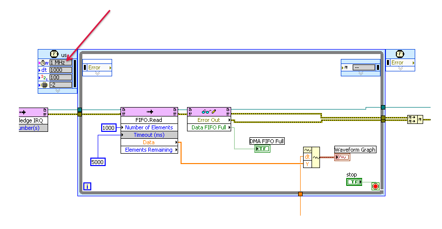
I have two codes for my NI9024 cRIO; an FPGA and a side side of RT.
In my RT code, I use a frequency of 1 MHz for my timed loop.
Just wanted to check if I should consider certain things important when using this frequency or not.
I mean, is there a particular point or referring to the fact that I had noticed.
Is there any limitation, future problem or question?
Just to be careful.
I think that the point that you are missing, it is that it is never necessary to update a graph 1000 times per second! operators just can't see that fast! So, unless you save the data on a disk, you can use a much slower pace of update. You can indeed, be limitation in this loop timed by your actual acquisition rate (timeout is 5 seconds - what is the sampling frequency of the FIFO?)
If the buffer is full or reduce the sampling frequency of the FPGA (a million points per second is really much more that a human eye can process) or increase the number of samples by reading.
-
What is the difference between REFin and PPSin? Can I use the PXI-5652 to synchronize USRPs?
Hello world!
I'm working on a project I want to synchronize 8 USRPs (USRP 2920) as receivers. And it seems that PXI-5652 has a connector REF, so I decide to use it as the reference of the USRPs 8 clock. But I don't know how to connect the PPSin, and in fact I'm confused of the difference between the REFin and PPSin.
Thank you!
Jay_c salvation,
In short,.
REF is the terminal for the device USRP to accept a signal from external reference frequency (10 Mhz).
PPS is the terminal for the device USRP to accept a signal from external time source base clock (1 pulse per second)
You can see this whitepaper for a detailed description of MIMO system about 8 * 8.
Please refer to the section "time and frequency" for information specific to your question.
http://www.NI.com/white-paper/14311/en/
I'm not sure whether you can use the specifically 5652 signal generator for your application.
-
Lack of charges, USB-6211 with linear gauge Mitutoyo (542 series)
I use a USB-6211 box with a race of 10mm Mitutoyo Linear Gage (542 series, model LGA-110). The Mitutoyo has output similar to an encoder without the time by rev signal quadrature. (B has a phase shift of 90 degrees of A). Signals A and B are airline pilots. I have a k 2 5V to A resistance and another 2K to 5V to B, gives me a minimum of 0.05v and a maximum of 4.75V.
The problem I encounter is that I seem to be missing certain counts that I can't always zero.
I found that if I caress the complete range of meter and the return to zero in 20 seconds, I get a value close to 180 meter microphone. If I press the complete range of meter and the return to zero quickly in a second, I get a value close to 800 micrometer.
If I caress the quick pledge on the compression and rebound more slowly, I find myself with a positive value. I caress the slow pledge on compression and quick on the rebound, I find myself with a negative value.
As I said before, it seems miss me certain counts. With a pulse of each mic of 4 meters, it means I get only 2500 pulses per 10mm. This means that 10mm per second is only 2500 pulses per second. It seems slow for me, so I don't know what would be the problem.
Does anyone have ideas for me to try?
With this type of signal you should not missing any counts. The time base on the box USB-6211 is 80 Mhz and therefore should have no problem to solve your two pulses per train. I have a couple of steps that I would like you to try troubleshooting.
1 to ensure that we plugged the inputs correctly to our DAQ hardware.
2 ensures that we use both the non-reversed or two signals reversed. Do NOT mix or 'type' of the signal.
3 allows you to wire signals A and B in two inputs analog and we will try to read signals to ensure that the sensor is actually be set correctly by the sensor. Be sure to taste pretty quickly--> 10 the frequency of the pulse train. If you race through 10 mm in 1 sec--> 2500 pulses per second--> 25 kHz sampling rate. Allows to check two things. First we have a good TTL signals, and that we get the right number of charges. If you reply to this thread plaese attach a screenshot of the present.
4. we will try different encoder types x 1, x 2, x 4 in the DAQ assistant. The x 2 and x 4 encoder allows the best sensitivity for small movements (which I'm not sure that it is the source of your proplem but it will be a good thing to check). Types of encoder are discussed in more detail in the following developer area: quadrature encoder measures: How To?
Let us know how it shapes to the top.
-
measurement time and openness 4132
Hello
I use a 4132 SMU with a switch 2531 to measure different resistance in an electric circuit. I use a brief biphasic pulse of 50ms ~ to measure resistance. My problem is the measurement time if long - it seems that the minimum pulse width I can do is a 30ms pulse in a polarity and a pulse ~ 40ms in the other polarity. I disabled 'way' that knocked 20ms on each phase, but I am still left with a ~ 70-80ms measure, but I wish it were half that, if possible. The only other way I can see to minimize the measurement time is at the bottom of the window opening, but any if I increase or decrease the time of opening, the measure takes about 10 x longer if the opening is none other than 1 PLC.
Attached is the Subvi I use to measure the unique resistance value. Note that first I close the relay to solve part of the circuit and then configure the SMU and then get several measures, one for V (+) and one for the (-) V. This measure will be repeated 15 times in quick, although succession with different closed relay, which means that the SMU gets reconfigured/initialized 15 times with the same parameters, so maybe that's my problem. I have not ventured into the handshake, but I would like to know if there is anything else I can do since the handshaking deal would take a lot of programming. In any case, when I run the VI several times, there are only 8 ms between biphasic pulses, so the reconfiguration may not take THAT long.
I posted a jpg file of the time trace of the impulse it generates (10,000 samples per second). Note that the first phase of the pulse is a different length of time that the second phase: there is nothing in the program that would cause - it would be more logical if the first phase was more time on behalf of increasing the time for the configuration of the SMU. So I have sort of a bunch of problems here: 1) cannot reduce opening time 2) want to avoid a handshake VI if it means hours and hours of programming, 3) uneven pulses. I hope someone can point me in the right direction!
Thank you very much
GimNPC
gimNPC,
As mentioned earlier, you should not call Reset every time at the end of the method. Instead, set the output to 0 c. Moreover, all the attributes that are not changed will not need to be reconfigured, which will speed up the loop a little (maximum, that I would expect several milliseconds).
When you call niDCPower Reset, the opening time is reconfigured. On the 4132, anytime, the opening time is reconfigured, must wait a minimum of time to allow a measure being erased. It is because of the behavior of one of the hardware components that we use. If you prevent the reconfiguration of your opening time during each run, your speed should be improved significantly.
Please let us know if these suggestions help, or if you have any other questions.
Thank you
Tobias Gordon
Software engineer
DC accuracy
National Instruments
-
Understanding on the 9505 FPGA VI speed control
I was able to quickly use the 9505 Servo Drive example for closed loop control of position on the FPGA, but I can't find how to change the code to take in charge the speed control (which I need to another axis). I'm doing my changes on the FPGA VI itself rather than on the side of RT Softmotion.
Here are the questions I have:
If I use the PI speed loop with my speed and a set arbitrary control speed, I see the speed stabilizes (engine power seems uniform), but I can't correlate with the other speed reference that a larger number is faster. Speed (from the loop of the encoder) seems collating in values from 0 to 2 just on my FPGA VI (I do not understand the units, but I see my position change on my collation of encoder in thousands of pulses per second). Why are they so different/how I have adapted my encoder speed correctly?
Using just the delivery example 9505 Servo Drive (position control), how to set the speed of moving of the FPGA code (in interactive mode)?
Hello
Speed is defined through position set points. Control of the speed in the screw RT does not actually send speed commands to the reader, but sends position set points at a known rate. Given that the position set points are sent at a constant rate, an effective speed can be calculated.
A method to do so via the FPGA would synchronize a loop in your FPGA code for the analytical engine, which has a known rate. Once this is done, you can calculate the actual speed of the engine.
-Erik S
Maybe you are looking for
-
I have an iPhone 5 s protected by a waterproof case, secure screw using Allen. This command removes the possibility of using the ID of the contact. Contact ID is required by the App Store! I found a way around locking the screen, but not found how to
-
Great list of 'How To' Questions
I am a newbie to iTunes learn the tricks of the trade, and I learned a lot of ed2345, who led me to still more questions: 1. a few songs that I managed to acquire have nothing in the kind column. So that this information will be available on the impr
-
How can I change the locale of Firefox?
Today, my administrator has installed another version of Firefox (version FrontMotion) to my machine. This version has apparently removed my German installation of Mozilla Firefox and installed in English. Now, all the shortcut keys, I use have becom
-
Hello My iPhone (iphone 6s 128 GB) updated to IOS 9.3 overnight. Now the links no longer work. For example, in Safari, if I google something and click the link, the Safari browser all crashes. Also, when I click on the links in my email, I have the s
-
Satellite Pro U200 supports PCMCIA cards?
Hello does anyone know if the PCMCIA, for example of Netgear WG511T card will work on Toshiba Satellite PRO U200?This laptop seems to have a PCMCIA slot.I know, I already have a wireless network card installed on this laptop, but this card is not sup