PXI-5154 making fried SMU-1075
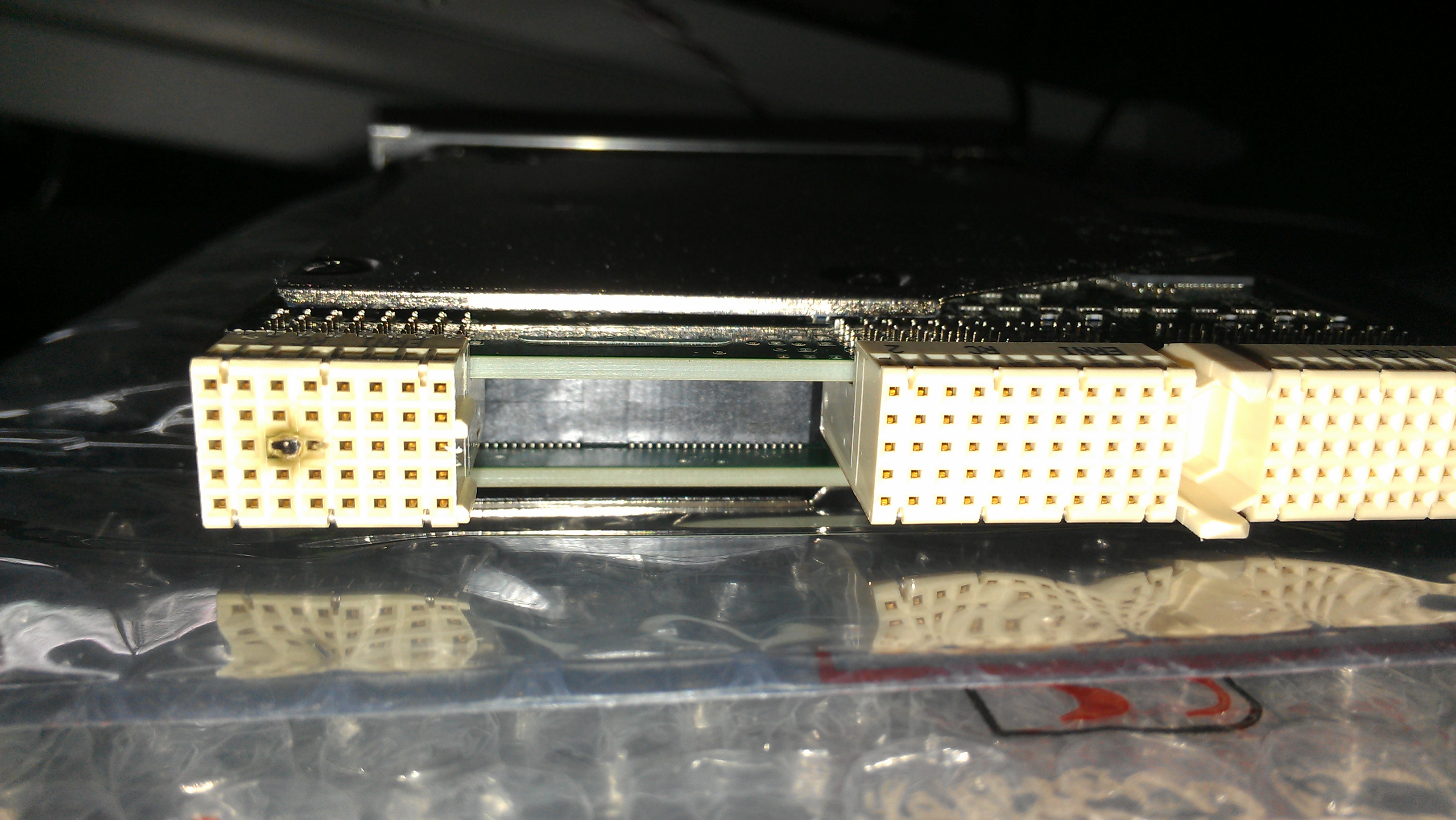
So, I just tried to install a PXI-5154 in SMU-1075 chassis. I followed the instructions that came with the card, but after turning on the chassis, there is no wizard detection of material, and no LED light came. I was going to try it in a different location, but when I slipped the card out of the chassis, I saw that looked burnt decision-making (see attached image). I'm not sure that I was wrong, and now I'm worried I might have damaged some of the other cards that have been installed in the chassis. So my question is double: 1) an idea of what went wrong here? 2.) nothing to say if the chassis itself is somewhat damaged? (3.) if the damage has not been caused by some error on my part of the user, is there an any warranty / replacement of the card?
Thank you
Well, turns out the instructions that came with the card were bad... the instructions say plug the card into a slot chassis marked with a number of cicrled, turns out I needed to plug the card into a slot with a number of cirled with a small 'H' beside him. Everything seems to be working fine now, thanks zeus
Tags: NI Hardware
Similar Questions
-
PXI-4070 appearing does not in the locations of SMU-1075 16 & 17
Hello
I have an SMU-1075 with the help of a remote SMU-8370/PCIe-8371, 4 SMU-6363, SMU 8-2351 and PXI-4 4070 s. The PXI - 4070 s are required to be plugged into hybrid slots (2-5 or 15-18). To maximize throughput, the 4070 s are plugged into connectors 4 and 5 and the other 2 are plugged into the 16 & 17 slots so that the DMM is divided to the use of 2 different PCI to PCI bridges. The issue I see is that the 4070 s 2 plugged into slots 16 & 17 are not displayed in NI MAX and in the Device Manager, display an error (see photos). I can see and use all other modules in the chassis, including the other 4070 s 2.
I have 3 other machines running in production with a configuration almost identical, the only difference is that the other machines use a PCIe-8372(or maybe an old model of the PCIe-8371?) The main difference is that the cards in the older machines have 2 ports but the model # is not projected on the cards so 8372 is a guess based on the installation booklets) host controller. The PCs are identical in all 4 machines: industrial Advantech, WinXP sp3, Intel core 2 Quad, 2 GB of RAM.
If I remove the PCIe-8372 among the machines to work and install it in the machine, with that I have problems, I can see and use all of the 4070 s so that we know that the PXI chassis and 4070 s are very good. I also tried all sorts of versions of different drivers and drivers uninstalled/re-installed several times as well as the solution provided in this post of 2011: http://forums.ni.com/t5/PXI/PXI-4070-DMM-in-PXIe-1075-Chassis-not-found/m-p/1609804/highlight/true#M...
I was wondering if anyone else has had problems similar to this?
OR Support Reference #: 2292623
It's a strange problem. If anything, from the 2 to the guest card guest card 1 port should help. A few things...
Have you tried the 4070 s 2 Slots 16 and 17 of the 15 to 18 slots? One of the effects of different host maps is a different interrupt for some legacy interrupts swizzling, and their displacement that will put them on the other 2 lines. It seems unlikely that the problem.
Another long shot based on the differences between the PCIe-8372 and PCIe-8371: try to remove one of the panels of the SMU of the system. Reason: PCIe-8371 requires little storage space. If we put a needle with how the PC will provide then reduce the requirement will bring the use of net memory to 0 (PCIe-8371 ask 1 MB, which is the minimum no no one can ask any card PCIe/SMU).
Have you tried the software of BIOS compatibility and the switch on the PCIe-8371? http://www.NI.com/download/MXI-Express-BIOS-compatibility-software-1.5/3764/en/
-Robert
-
Acquire more than 2047 samples with the PXI-4461 instaled in SMU-1073
Hi all, I would ask you for help with the buffer limit.
I intend to buy digitizer PXI-4461 and he instal in SMU-1073 chassis, namely control via MXI Express of Labview installed on a separate computer.
What I need:
-to acquire data of a single channel of AI, but at least a sequence of 20 kS by a acquire task, in some situations until 200kS by a task to acquire.
The question:
- I can gain more than 2047 samples in a single sequence, like 200kS, with the PXI-4461 installed in SMU-1073?
Internal buffer of the PXI-4461 is reserved to 2047 samples. So I'm not sure if Labview can download remotely via MXI Express the data in the buffer of the PXI-4461 via MXI Express fast enough without any affection of the sampling program.
-in the case, this PXI-4461 with SMU-1073 isn't the right combination, what chassis and a controller can do?
Thanks much for the reply
Jan
It will work for you.
The on-board buffer 2047-sample is used only as a backup if the flow of data to the PC host (via MXI Express in this case) is not fast enough... that it will be (explained below). DAQmx transfers data from the buffer of the device to the host PC as fast as he can and, in ideal conditions, should not save the buffer 2047 much at all.
Let's just say you get 110 MB/s (randomly from a MXI data sheet) flow on your MXI connection. The 4461 has 2 analog inputs, which will be at 24 bits, we just round 32-bit in case it transfers the data in this way.
4 bytes/sample (32 bit) x 200,000 s/s x 2 (channels) = 1.6 MB/s, which is well below the 110 MB/s, which will make the MXI link.
clear as mud?
Germano-
-
Usability is NOR-SCOPE Soft Front Panel for the PXI-5154?
I am plans to use the PXI-5154 with his NO-SCOPE Soft Front Panel in a product to test instrumentation. Our past experience, our users need an on-board scope that is easy to use which does not load the CPU. In most cases the scope will be used to check a transitional type of pulses. So, the amplitudes and rise times are essential to ensure compliance with ISO standards. The ability to capture, store and recall traces of reports is important, as well as the ability to perform simple and reproducible follow-up measures. We don't expect our users to have to program the scope; "give me the waveform.
Does anyone have any comments on the usability of the NOR-SCOPE Soft Front Panel? How to compare with other soft scopes?
Hello!
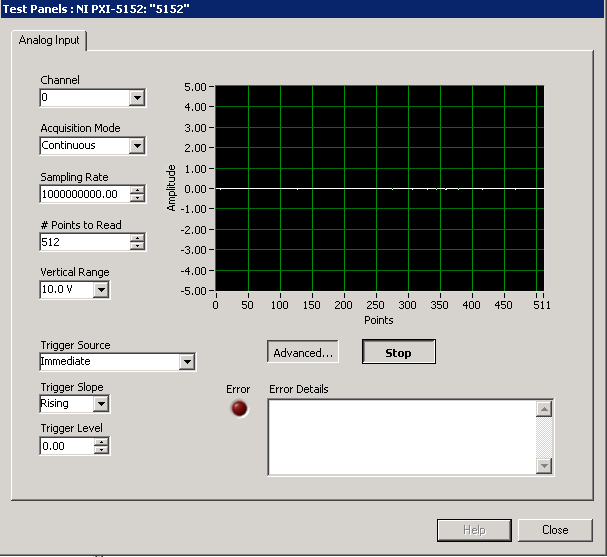
The scope Soft Front Panel is very user friendly and able to load/save waveforms, Load/Save settings and make the scalar measures. I've attached a screenshot of what the front soft worn looks as well as a link to a help document on the high speed digitizer HELP. Information on the scope Soft Front Panel lies in this document and can be found under the tab content in the configuration tree (NI - Scope Soft Front Panel help).
Help of digitizer OR high speed
http://digital.NI.com/manuals.nsf/WebSearch/2123F564C6DE7B27862574DE006915DE
-
PXI-6534 replacement by SMU-6537
I am currently ordering and receiving data from a device to measure with the PXI-6534, LabVIEW and DAQmx on Windows.
Can I replace the PXI-6534 by an SMU-6537 without having to change anything to my hardware (will be in other words, the cable connections and advice sheet be compatible)? If so, the code written to communicate to the PXI-6534 will be reusable with the SMU-6537?
Thank you comments or pointers.
X.
I'm really sorry, but I forgot to mention in my previous post that there is indeed an adapter that will allow you to use the same block that you used with the PXI-6534. You can find more info on this adapter cable on this link:
-
Hello
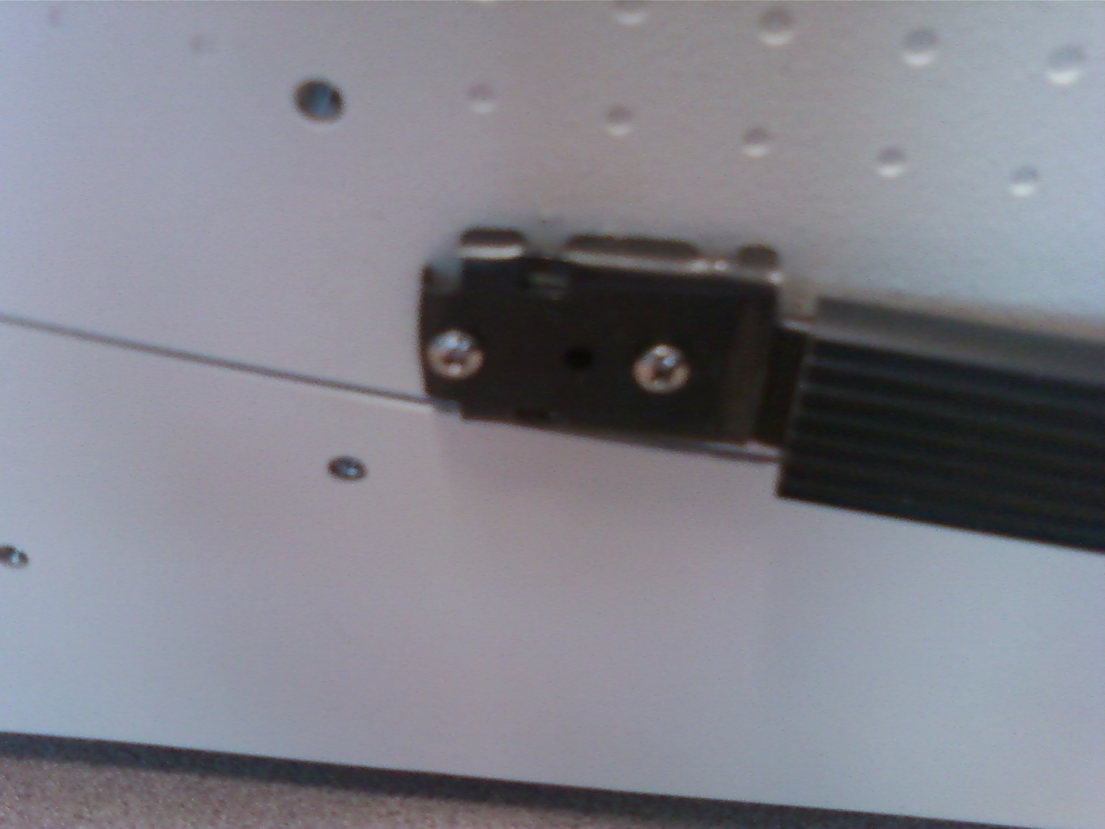
I have a NI SMU-1075 chassis that needs to go in a rack temporarily. There is a handle that allows you to pick the thing up and carry it on the side. I can't, for the life of me, understand how to remove the handle without having to take part the whole chassis (something I would avoid because the equipment isn't me). I googled this and found sparse information about the subject...
Thoughts? Advice? Points of view?
Hi RS_233.
The handle can be removed without removing the chassis. There are two bolts phillips head as the bolt on the side of the chassis that anchors on each side of the handle. They are accessible by removing the black access plug that covers the handle anchor. Use a screwdriver to remove the black cap, taking care not to scratch the frame. See the image below for a representation Visual of what I'm talking about.
After removing the black cap access, you can unscrew and remove the anchor. I hope this helps!
-
5154 PXI trigger on the external input
I use a PXI-5154 and want to change my previous program to trigger the external source. I'm feeding the external source from source to V 2.5 and it seems to trigger fine. However when data acquisition the vertical range of the oscilloscope will 5 V which is too high as to my request I acquire in the millivolts range. I tried to show the vertical range of the channel I acquisition, but although I put it as the active channel I get the following error:
Error 1074118616 has occurred to the property node (arg 1) in PD_measurements_v11_test.vi
Get a base attribute value channel failed because the channels interviewed have different values. Please specify a channel when you query a string based attribute.
I enclose you a printsceen of the relevant part of the code.
Kind regards
Karavellas
Dear Tunde
I managed to make the changes you suggested and the works of the example. I'll look in my code and see what the problem is. I'll get back to you if it has been fixed in my code or not.
-
Dear community,
I am trying to implement a background basket (software) PXI trigger on a chassis NI SMU-1082 with LabView 2015 (32-bit) running on an SMU-8135:
HS-DIO (SMU-6544) in slot 2,
-Acquisition of data (SMU-6363) into the Groove 4,
-Flex RIO (SMU-7962R + OR-6583) in the Groove 3.
The trigger schema is explained in the attached file ' LV-PXItrig-HSDIO-DAQ - overview.jpg ".
Scenario 1: written DAQ analog signal and sends signals trigger HS-DIO (software) through bottom of basket, after East of waveform of the complete signals to DAQ for acquisition.
Scenario 2: logical impulse on an external port HS-DIO triggers signals HS-DIO, after HS-DIO waveform is complete DAQ triggered for the acquisition of the ADC by the backplane.
In principle this breaks down to send a trigger of module A to B by PXI backplane. The SMU-1082 chassis has a bus trip with 8 lines (PXI_trigX, X = 0,..., 7) more a trigger in Star controlled the slot 2.
I've linked to implement a software trigger, but I can't access the refreshing resource and execution, see the attachment. Other ways of implementation including the DAQmx Terminal / routine disconnect Terminal have not worked for me either. I am aware about the connection of trigger using the node property VISA but I can't make a trigger.
Tips, comments or solutions are appreciated. Thank you!
For scenario 1, you want to trigger the HSDIO acquisition to begin as soon as the analog output DAQ starts? You can use
DAQmx Export Signalto send the trigger for the start of one of the lines from the Trig PXI backplane. Then, you need to configure your HSDIO acquisition to use a trigger digital beginning on the same line of trigger. Take a look at the example of the "Dynamic hardware generation start trigger" in the Finder of the example (help > find examples)For scenario 2, looks like you do a dynamic unit HSDIO generation when a digital trigger arrives on one of the PFI lines. Once the build is complete, you want to send a trigger for the DAQ hardware to begin sampling. If this is the case, you again use a trigger to start material in your task of NOR-HSDIO, as you did for scenario 1, but use external trig line as the source, rather than the bottom of basket. There is no case of material when the build is finished, but you can use a marker in script mode event instead. The example of the Generation with dynamic event marker' in the example Finder gives a good starting point for this type of operation. You'll want to set the output terminal for the event to be a line of backplane trig, and then tap the DAQmx to start on the same line trig trigger.
-
How to build a parser of vector signals PXI using different module combinations
Normal
021
fake
fake
fakePT - BR
X NONE
X NONEMicrosoftInternetExplorer4
/ * Style definitions * /.
table. MsoNormalTable
{mso-style-name: "Table normal";}
MSO-knew-rowband-size: 0;
MSO-knew-colband-size: 0;
MSO-style - noshow:yes;
MSO-style-priority: 99;
MSO-style - qformat:yes;
"mso-style-parent:" ";" "
MSO-padding-alt: 0 cm 0 cm 5.4pt 5.4pt;
MSO-para-margin-top: 0 cm;
MSO-para-margin-right: 0 cm;
MSO-para-margin-bottom: 10.0pt;
MSO-para-margin-left: 0 cm;
line-height: 115%;
MSO-pagination: widow-orphan;
font-size: 11.0pt;
font family: 'Calibri', 'sans-serif ';
MSO-ascii-font-family: Calibri;
MSO-ascii-theme-make: minor-latin;
MSO-hansi-font-family: Calibri;
MSO-hansi-theme-make: minor-latin;
mso-fareast-language: EN-US ;}Normal
021
fake
fake
fakePT - BR
X NONE
X NONEMicrosoftInternetExplorer4
/ * Style definitions * /.
table. MsoNormalTable
{mso-style-name: "Table normal";}
MSO-knew-rowband-size: 0;
MSO-knew-colband-size: 0;
MSO-style - noshow:yes;
MSO-style-priority: 99;
MSO-style - qformat:yes;
"mso-style-parent:" ";" "
MSO-padding-alt: 0 cm 0 cm 5.4pt 5.4pt;
MSO-para-margin-top: 0 cm;
MSO-para-margin-right: 0 cm;
MSO-para-margin-bottom: 10.0pt;
MSO-para-margin-left: 0 cm;
line-height: 115%;
MSO-pagination: widow-orphan;
font-size: 11.0pt;
font family: 'Calibri', 'sans-serif ';
MSO-ascii-font-family: Calibri;
MSO-ascii-theme-make: minor-latin;
MSO-hansi-font-family: Calibri;
MSO-hansi-theme-make: minor-latin;
mso-fareast-language: EN-US ;}I understand
Vector signal analyzers OR consist of 2 or 3 separate PXI modules: 1
digitizer, 1 buck converter of RF frequencies and 1 generator of signals (model 5663).1. can I use digitizer and signal
generator general purpose oscilloscope and generator of signals separately?2 may I build my own VSA by choosing
different combinations of scanners and the signal generators? Or replace the signal
generator by an arbitrary signal generator?3. I
intend to buy a digitizer/oscilloscope and an arbitrary signal generator
analysis of response of frequency on the transformers. Later I plan to
buy a step-down converter frequency and build a vector signal Analyzer. Is this possible?Hello
The frequency IF the 5660 and 5661 (it's the same thing) is 15 MHz, with an instantaneous bandwidth of 20 MHz. The difference between the 5660 and the 5661 is located in the digitizer that accompanies it. The 5660 uses the PXI-5620 digitizer that has a sampling rate 64 MECH. / s and a buck converter of digital frequency limited to 1.25 MHz of bandwidth. The 5661 uses the digitizer PXI-5142, giving you a MECH 100. / s rate and a PSO allowing digital downconversion circuit and the decimation of the full bandwidth of 20 MHz.
The common comment in the SBA above is the RF PXI-5600 frequency step-down converter which is a superheterodyne architecture of three floors. OL is for the three stages of this module are auto-approvisionnées in their own country. The architecture of several step allows for rejection of the improved image and filtering at the expensive of a noise floor slightly higher due to the signal path more complex. There also an OCXO on board, this gives him a time reference more precise - noise reduction phase etc. The PXI-5600 by itself is wide from three locations.
The SMU-5601 since SMU-5663 step-down is designed based on the single frequency step-down converter and resumes from a single location. The celled frequency step-down converter gives you improved noise floor characteristics and a better dynamic range, with the rejection of the image fees, having does not simply because there is only one step. The LO is provided by an external module in this case for several reasons. Have a separate external LO allows more modularity in your system, as well as the ability to share a single LO generator between several vendor-specific attributes. This opens the possibility of MIMO applications. The internal of the NI PXI-5600 LOs are not shareable and therefore cannot be synchronized between several PXI-5600 s. The PXI-5663 (all three modules) takes up the same amount of space in the slot as a single NI PXI-5600 without a digitizer.
The PXI-5154 is indeed a powerful scanner, given its instantaneous bandwidth of 1 GHz. Remember, however, that the connector Active Directory on this digitizer is 8 bits, compared to the 5622 which is 16-bit. If you need more resolution is of course entirely depends on your application. The PXI-5600, as SMU-5601 is controllable as a buck converter stand-alone frequency using the DAMA API OR. You will need to program your application with the scope API for use with PXI-5154 OR and the API de DAMA. A few other caveats to note is that there is no PSO on the PXI-5154 so you can't enjoy the Equalization filter to correct the frequency of the NI PXI-5600 response. Also, as I mentioned above, the frequency of YEW of the NI PXI-5600 has 15 MHz with a bandwidth of 20 MHz - processor 1 GHz bandwidth on your digitizer will be somewhat of an overdose of the IF signal.
While you're dead on with the advantage of modularity, I would take the time to really meet your search application and ensure that different choices of module and their combinations to meet these needs.
Hope that helps!
-
Hello
I am currently in a period of training, and I try to install a banch instrumentation for my tutor.
So I have a SMU-1075 chassis, which is connected to my computer by an SMU-8370.
There are 3 modules:
PXI-4071
PXI-5422
SMU-5122
For the first two I have no problem to see at MAX. But the last of them does not appear in MAX?
I installed LabView 2010, also NEITHER Scope and provides many other software with my products.
Can someone help me? =)
Hi Thibloiz,
What version of NOR-Scope? You should be able to get the version # in the list of software in MAX.
Have you tried the 5122 in other locations of your chassis? It shows in the Windows Device Manager?
-
ERROR-235140 SMU-4139 self-test
Hello
I get an error with my SMU-4139 module. I have a chassis SMU-1075 configured with 2 NI PXI-4070, NI SMU-4139 2 modules and 3 NI PXI-4130 modules.
When I start my computer, a SMU-4139 module lights up with green and active green access light. The other SMU-4139 module will turn - on the same path, but in a short time, access turns off the light and the light turns red. I tried to run the automatic test NI Max, but I get this message.
The test failed.
-235140
Internal hardware error occurred in Power_Supply material. Please contact the support of National Instruments.I tried to change its slot SMU, but I got the same error. Should I send this card in Checkout?
Thanks a bunch!
Hey,.
I wanted to give an update about it. I uninstalled OR-DCPower (I think I got the version installed 1.9) and installed NOR-DCPower version 14.1. Everything works very well.
-
Hi all
I have to do a test system optimal hardware configuration OR for an application where the system should simulate Serial interfaces, interfaces to MIL STD 1553 and analog, Digital O/Ps & I / PS. Modules OR for the best match for this requirement were NI PXIe4322, 4300, 6363, PXI-6624, 8430/4,8431/8, Pickering two rtd PXI cards and a card of 1553 PXI SMU-1075 controller SMU 8840-frame. BUT this current price of configurations will on budget than we expected. for this reason I think to change this part and part PCI system in 6363,6634 tax SMU system, serial interface cards and card MIL 1553 with a PCI/PCIe platform and keep the rest of the map with the SMU platform chassis and eliminating controller SMU 8840. So can I use MXIe controllers to implement this system of type test so that I can put all the pci cards in a high-end modules SMU and PC and industrial PXI chassis SMU (1065/1075/1078 one)? If so please guide me what controller MXIe to choose and what would be the compatibility problems that may occur with this type of system in the future.
Thank you
My experience with USB has been nothing else to headaches. So I wouldn't go the route of USB. Normal PXI slots can also accept the cPCI, so you could look for those as well. If you just need a very simple map of 1553, I'd go with 1553 Excalibur cPCI card. I used their cards and they work fine. Drivers LabVIEW need a cleaning, but they can be used. This card is a simple send and receive, so if you need to do some testing of weird signal integrety (I don't remember the number of test at the top of my head), this card will not work for you. But this card was sever thousand dollars less expensive than the GOAL cards, I also used.
-
Error codes 12, 31 - PXI my system does not work
I tried to solve the erros on my pxi system using the software compatibility MXI-Express BIOS 1.3 - Windows 7 64 bit/7 x 86/XP x 86/Vista Vista / x 86 x 64
This software is intended to solve error code 12 or 31 showing in windows Device Manager. But this software does not support any system with material that contains several bus root PCI Express, only those with bus single root. But according to this software, my computer has MULTIPLE ROOT PCI EXPRESS BUS. What to do next? Windows just don't recognize my PXI system. There are two screenshots of the error.
My description of the system:
Dell precision T5500 workstation
Windows 7 64 bitPCIe-8371 x 4 connected to a x 8 slot
Controller of SMU-8370
SMU-1075 chassis
Step-down converter frequency PXI - 5600 RF
Digitizer PXI-5142 OSP
Converter RF PXI-5610
SMU-5442 AWG OSPI appreciate the help.
Filipe I think I can help you here. With the T5500, we should try to slot 2 or 4. We saw some problems of special interruption with Dell 1 slot and you can or can not see this behavior too. Unfortunately, I have all the details on this issue. However, there are also a known issue with Dell BIOS that limits the PCIe bus range, which can cause unexpected behavior when you extend your PCIe via MXI-Express bus.
That leaves us with two options:
1. we can update your BIOS to not have the bus number so low limit range
Dell may have a BIOS available for the T5500. You can contact Dell Technical Support and maybe ask an other BIOS that has been released - it's not available on the Web.
2. we can try to take advantage of the v1.4 MXI-Express BIOS software compatibility, supporting multi-root complex
You need to register for the beta to ni.com/beta software. Once approved, you should be able to download and install accordingly.
I'll send you a PM about #1. I would like to help us as much as possible.
Kind regards
-
Identify the PXI properties to decide if you want to route triggers on PXI bus segments
I have an SMU-1075 and a SMU-1062 q chassis. Each has a similar map configuration.
Initially, I developed my request for the chassis PXIe1062Q, routing a trigger by the generators of card synchronization signals and a digitizer. When I run it on the chassis of 1075, I send 2 to the segment of bus 1 bus segment triggers so that triggers the calendar cards reach the scanners and the signal generators. On the chassis of 1062 q, this is not necessary since everything is on the same segment.
I used the article routing programmatically Trigger lines through a Multi Segment PXI, PXI chassis to properly route my trigger.
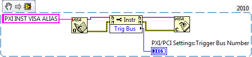
Is there a way to determine how many bus segments I, or Wow, I use to do I connect automatically triggers (or not), so that I can use the same VI to control two hardware configurations? I don't know what happens if you try to connect through triggers of bus segments that doesn't exist may not, but I wanted to know what is the correct way to deal with this situation.
You could pull the trigger bus number using NI-VISA. Just give your devices one alias VISA to the MAX and you can use a node of VISA property to get the number of PXI trigger bus. This should help you.
Best,
-
Hello!
Has created the 5154 digitizer. A few months everything worked remarkably.
Yesterday did not socket TRIG, PFI0, PFI1.
Tension has sent 1 - 2V.
The device past self-test successfully. Calibration and reset devices did not help.
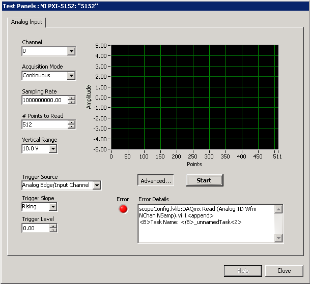
I start with autoparameters test Panel. I put the synchronization on TRIG and there is an error: "scopeConfig.lvlib AQmx Read (analog 1-d Wfm NChan NSamp) .vi:1.
" Task name: _unnamedTask.
What should do? How to fix?Hello
Let me assure you that I have a complete understanding of the problem. You use one OR PXI-5154 digitizer that passes the self-test and performs a reset of the device and automatic calibration without any error. If that's the case, then it most likely is not a problem with how the device communicates with the controller and probably not a problem with the device itself. I have performed remotely in one of our systems of PXI here and was able to reproduce the error of test here panels and got the same error as you. My screen looks like this:
If you do not trigger options, click on the Advanced... button. Is this the same problem you are having? If so, what if because it's never really recieivng this source of relaxation. I could define an immediate Tigger and run without error. For more information on scanner triggering, seethis article from DeveloperZone.
It would be also interesting to watch the NOR high speed scanners Getting Started Guide , particularly on page 21. You mentioned that you have problems with TRIG, 0 to PFI 1 PFI. TRIG is for connections external triger analog, and PFI lines are for reference in sample clock clock in and digital triggering input/output. None of the signals related to it are in fact going to be digitizerd. "" "" "You can also find more information about this digitizer and triggering by going to start ' programs ' National Instruments ' NOR-SCOPE" Documentation "high-speed digitizers help. "" This will open a HTML file and go help scanners high speed OR "devices" 5153/5154.
I hope this helps!
Maybe you are looking for
-
Drag files from a folder on the docking station to a folder in the finder (El Capitan)
We have recently improved Mavericks in El Capitan at work and I noticed some lost (apparently) features. Is no longer, I can click on my downloads on my dock folder and drag a file into a folder in the Finder. When I try to do it now, nothing happens
-
Re: Tecra M2 - where can I buy the new internal speakers?
Hello My speakers in the Tecra M2 have blown, essentially when I turn the volume up to half way he screams a horrible noise, and I can hear the dogs barking in the background! Where can I find new speakers for her?Had a look on ebay but they do not a
-
My computer laptop cursor freezes sometimes when they surf the internet from 1 website to others while in the middle of data transfer. All functions stop. Everything tried but failed. Have to power off of closing down, cos nothing move. When turn on,
-
Password bios HP G62 needed please. 80225536 Thank you
-
HP Pavilion g7-1154nr Notebook PC - memory upgrade
Hello! I was wondering if the new memory, that I bought for my laptop will be compatible. I want to especially know that before I opened the package, they came, being eBay. I have a HP Pavilion g7-1154nr Notebook PC and I bought laptop G.Skill DDR3 m