PXI-6120 digital output frequency
Hello
before that I have to post my question some technical information:
LabVIEW: 2011.
IO digital 8 PXI-6120.
I read the user manual and search the Forum and there is no reference to the frequency of digital output (only for a meter).
My question is what is the maximum frequency that I can generate outputs digital?
The best I could do is 50 kHz using the example.
Thank you
Sokal
Tags: NI Hardware
Similar Questions
-
OR PXI-6289 Digital Output Solid State Relay
Hello
I try to control a mechanical solenoid pull using a relay of sold State connected to my PXI-6289. Currently I have the CRDD connected to Port 1 line 4 and use the code provided here http://zone.ni.com/devzone/cda/epd/p/id/6411 . However, every time I run the code, the light on my SSR (wired to show the logic works http://www.adafruit.com/products/268) does not illuminate indicating that there is no signal to be output. Any help in this matter would be much appreciated. If additional information is needed please let me know.
Best,
Brad
Nevermind, problem solved it was just low power.
-
Digital output frequency seems to be twice the frequency generated by the basic function generator
Hi Labview forum,
I wrote a program (attached) Labview to generate 3 PWM, square wave, signals that has the same frequency and phase delay right (so that when a signal is off, the other signal is lit. Then the next signal). Everything seems to work fine except that the frequency of the PWM signals generated seems twice as the frequency given to the basic function generator. Anyone have any idea why this is happening? Anyhelp would be greatly appreciated.
Thank you!
Totally agree with the advice of all GerdW than the hardware timing of your hardware DAQ will be much more reliable. That said, part of what you are probably hitting is a little quirk of the primitive delay msec. Requests for 1 msec have long been particularly little reliable (although they * seem * to have improved in recent years, probably due to the better OS support in Win 7 or something).
I did minimal mods to your code with comments from you switch to a timed loop. My quick test showed he is good enough to hit the 1 length of loop of target msec.
-Kevin P
-
separation of two edges using a digital output
I am using a DAQ, PXI-6229 map and programming in c# .net.
I'm claiming a falling edge on PFI12 used as a digital output, and I need to measure the time between this edge and a second front on PFI8 used as a digital input. I have implemented the code using some examples I found. I don't know when to to argue the signal on PFI12 in order to be read at the right time. Playback must be put in place before the signal is asserted, but I do not know how to set it up it up properly.
Here is the code I have so far:
Public Sub MeasureAcquisitionTime()
{
DigitalSingleInputTask = new Task();
CIChannel counterSetup;
firstEdge = CITwoEdgeSeparationFirstEdge.Falling;
secondEdge = CITwoEdgeSeparationSecondEdge.Rising;
Double minTime = 10-3;
Double maxTime = 60F-3;
String auxCounterInput = "/" + CardName + ' / PFI12 ';
String gateCounterInput = "/" + CardName + ' / PFI8 ';
counterSetup = DigitalSingleInputTask.CIChannels.CreateTwoEdgeSeparationChannel)
CardName + ' / ctr1 ', 'counter',
minTime,
maxTime,
firstEdge, secondEdge, CITwoEdgeSeparationUnits.Seconds);
counterSetup.TwoEdgeSeparationFirstTerminal = auxCounterInput;
counterSetup.TwoEdgeSeparationSecondTerminal = gateCounterInput;
DigitalSingleInputTask.Control (TaskAction.Verify);
runningDigitalTask = DigitalSingleInputTask;
counterInReader = new CounterReader (DigitalSingleInputTask.Stream);
Double data = counterInReader.ReadSingleSampleDouble ();
}I'm glad to hear it.
paofthree wrote:
Is there a way to make a measure of separation of two edges on the analog inputs of the PXI-6229?
The only way would be to constantly acquire the analog input voltage and calculate the separation of the two edges in the software.
Best regards
-
Hallo,
I use the following system:
- OR PXI-1044 with controller NI PXI-8109
- OR PXI-2564 switch module to turn on the monitor of my test device
- Data acquisition multifunction NI PXI-6259 to measure the signal that responded to the questionnaire jump
The two cards are the same - PXI trigger bus. For both, PXI-2564 and PXI-6259 I use DAQmx to set the reading and writing of the channels.
Now, I want to measure the time between the digital output, my unit turns and the analog input, which measures the response of my system.
I can't do work by myself, please help me!
I thank Ludwig.
Hi Ludwig,.
If you can't give us any VI we have difficulties with to help you.
Because I Donat knowledge how your program is mounted it is not easy to know where you should enter signals.
Here's a question similar to yours:
http://forums.NI.com/T5/LabVIEW/best-way-to-measure-time/TD-p/178704
and 2 external links:
http://www.ehow.com/how_8698983_measure-time-LabVIEW.html
http://objectmix.com/LabVIEW/385152-how-can-i-use-LabVIEW-measure-time-between-analog-pulses.html
-
analog sync of input with the onset of the digital output
I'm trying out an analog signal to a file with a specified frequency samples. I also need a digital output to trigger a measurement at a frequency specified on a separate system. The frequency is controlled by the loop exits and timed when the iteration number divided by the period is exactly a whole number.
Both outputs work. The problem is that they are not synchronized. The analog output amounts to about 0.5 ms faster than the digital signal. (I checked with an oscilloscope) They both start in the 1 ms each loop runs for, but I really need them to start at the same instant. What can I do to synchronize? Also, if I'm going in the wrong direction complete, please indicate.
I use a card PCI-6723, which I think someone at some point, said not having a material sample clock. That's why I try to use a timed software loop.
Hi NEA.
You must use the 6723's built-in calendar to accomplish what you want. As the digital output subsystem is only clocked by the software, an appropriate solution should be to use one of the counters to the pulse output.
The attached code should show how. You can use the counter to output a pulse all samples of the AO N task. Material requires the initial delay to have a minimum of 2 ticks, so the meter will be behind the task of the AO by 2 samples in this case. There are different ways to work around this problem if you need (for example write two samples of 0 first).
Best regards
-
digital output microsecond LED timer
Hey all,.
I'm doing a table of 10 LEDs in a row to form an analog timer to use to characterize the delay of the shutter on a digital SLR. We'll first stage shutter lag on the camera using a method different and well set the delay of the shutter for interior<1ms. i="" am="" trying="" to="" use="" labview="" alongside="" a="" ni="" usb="" 6251="" using="" an="" sc-2345="" for="" access="" to="" the="" digital="" outputs.="" im="" using="" a="" timed="" structure="" and="" a="" timed="" loop="" to="" ensure="" the="" timing="" between="" each="" led="" turning="" on="" corresponds="" to="" an="" actual="" time.="" however,="" i="" am="" not="" getting="" the="" results="" i="" thought="" i="" would.="" the="" timing="" does="" not="" seem="" to="" be="" what="" i="" thought="" it="" would="" be="" and="" i="" can="" not="" get="" the="" timed="" loop="" to="" work="" with="" all="" the="" channels="" at="" the="" desired="" frequency="" which="" would="" idealy="" be="" as="" high="" as="" possible.="" could="" someone="" take="" a="" look="" at="" my="" code="" and="" provide="" me="" with="" some="" insight="" where="" i="" may="" be="" getting="" issues?="" i="" apologize="" if="" i="" am="" overlooking="" important="" information="" that="" may="" be="" needed="" to="" help="" solve="">
~ Aaron
I have no DAQmx I can't be sure. I think that the 6251 has a maximum rate of 1 MHz in order to try to set the rate to 20 MHz should generate an error. For the purposes of test on the rate 1 Hz bit or less. Then you should be able to see the LEDs as turning on and off.
You may also need to set the number of samples to the size of the array. Referring to the size of the array fed to Scripture DAQmx, not the table on the front panel. With the number of samples set to 1, I would expect that he wrote that the first element of the array that is equal to zero. That does not produce a very interesting performance: he lets just all lights off the coast!
Lynn
-
How can I more easily generate a pulse of digital output of finite length?
Hello
I need to open and close the two pneumatic valves using a TTL output (without load current or the output power) using a PCI-6280 or PCI-6601. The valves must open almost simultaneously and closing after different amounts of time elapsed (millisecond level timing, maybe 100 microseconds-level timing at worst). My current plan is as follows:
-Create a task with two digital outputs (type of waveform) and another task with a counter that generates a frequency set by the user (I know I can use the generator frequencies on one of these cards, but I would have preferred a counter - the best selection of frequencies).
-Wire the output of the counter at the entrance to clock two digital outputs.
-Output of the meter is digitally triggered by another digital channel which I use to control if the pulse goes out. Through its counter node, it is programmed to be redeclenchables.
-Two digital waveforms are drafted who have both consist of unique active high pulse (i.e. signals go ' down (for the amount of time user-defined) - low ".")
-These signals is written to their respective ports and their tasks have started, as is the task of the meter.
-Whenever the user wants to open taps, digital triggering is sent up and then back to low (this can be done with synchronization software, because it is not exactly when the fire valves). Whenever the user wants the valves open for a different period, different digital waveforms are generated and written in the buffers of the digital output channels.
My problem is that it looks like a lot of effort for me to go and I wonder if there is a much simpler solution, that I don't know everything. You can program a computer to produce a pulse of finite length? Is there a faster way to program a digital output for that channel?
Thanks to anyone who responds to their help.
It is certainly instructive. Thank you.
The thing is, I have only six total counters to work with and I have a lot of time to do things. To use these solutions, I would need to use 4 or 6 account counters required to my needs.also that I would need to synchronize their departures.
Overall, I stick to my method for now - less system resources and synchronization can be don by using the same meter of finished output clock and not to use a trigger to all.
Once again, thank you for your help so far.
-
PXI-6527 digital i/o ports does not
I couldn't get my two PXI-6527 work.
In MAX, my devices are recognized, they pass the self test, and I can set high or low output on a specific port and a line on the PXI-6527 using the test Panel. When I take a measure to that line, say-5,7 to + 5.7 (port 5, line 7), I do not read any voltage. I tried the same thing by using one of the digital outputs LabView examples, without a bit of luck. I tried several different ports and lines on maps two PXI-6527.
When I measure the PIN "GND" to the "+ 5V" pine, I read 5V on my multimeter.
I have several other DAQ with e/s digital equipment on them (PXI-6025E, PXI-6704, PXI-6221), and I managed to create on the digital I/o output voltages.
Y at - it something that I do bring my digital output signals to PXI-6527 maps.
Hey Jake,
The output of a device 6527 channels are static relays with a LED and two MOSFETS connected together to form a two-way switch. The output channels will not output a TTL 5 V signal without providing an external source. Using the V + 5 of unit 6527 line allows you to use it as a TTL level with power not isolated output device. See sections 3-10, 3-11 6527 user manual as a reference for the above information.
Thanks for choosing National instruments.
Kind regards
Glenn
Technical sales engineer
National Instruments
-
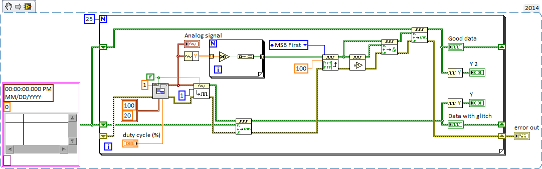
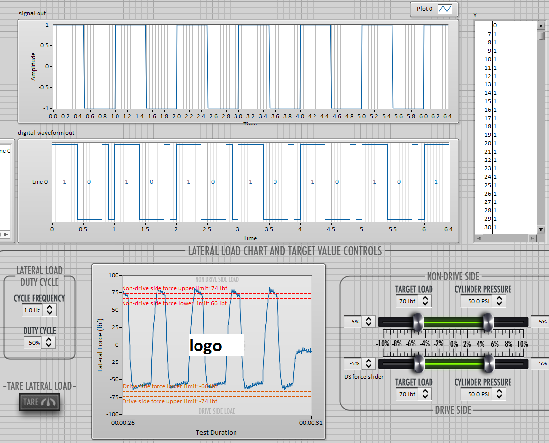
Waveforms digital output duty cycle glitches
I try to use a square wave converted to digital output to operate some solenoids but seeing some problems with the cycle on the digital waveforms. The output frequency will always be of the order of 1 Hz and duty cycle must be adjustable to integer values. I have attached a simplified below, demonstration that shows the digital/analogue output VI I used initially. the problem with this VI, is that if I choose a cycle that is not a multiple integer of my samples for waveform I get seeds. If I use the Boolean digital VI table this problem disappears in my simplified code, but in my real program the problem reappears.
This image shows the waveform analog generated as well as the digital output that results.
In the digital waveforms, you can see that the duty cycle of 50% is sometimes applied during the single loop (~.2us) instead of more than 1 sec iteration, although the curve of actual load indicated in the table at the bottom seems to suggest that LV ignores this glitch (somehow). As I said, the problem disappears if the duty cycle is an integer multiple of the sample/loop. Timing of the loop is torn apart by other e/s to 2 000 Hz/400 samples per loop and 100 Hz/20 samples per loop (large enough VI otherwise I would include it). Obviously, I could change them to get 50% as a multiple, but this does not solve the problem if user needs to adjust from there.
Can someone point me in the right direction here? I'm sure that there is a stupid/easy solution, but I can't seem to get.
Thank you!
You might try turning the inputs A and B of waveform of the VI of the digital samples append. It seems that A should be the fate of the shift register data (the original data) and B should be added (the new waveform) data anyway, at least conceptually.
Paul P.
Engineering applications
-
How to synchronize 2 digital output channels that have been created with DAQmxCreateCOPulseChanFreq
Hello
I use peripheral USB6221.
I created two digital output, operating on a frequency of 75KHz and duty cycle of 50%. But I need a period of 1 microsecond between the two channels.
I have craeted the two channel on the same task and guess if I use a delay of 0, the channels will be synchronized, but looking at the scope, the channels are not synchronized. Here's the code I used (I checked also all return codes of coarse and fine).
Thank you
Danny.
Int32 RetCode;
RetCode = DAQmxCreateTask ("", & m_OCtaskHandle);
LogMessage (RetCode, "CreateTask", "");
If (RetCode > = 0)
{
define the first output channel for 1 transmitter (75KHz)
RetCode = DAQmxCreateCOPulseChanFreq (m_OCtaskHandle, "/ Dev1/ctr0", ")
"Transmit1 Line 1", / * name to assign to the channel * /.
DAQmx_Val_Hz, DAQmx_Val_High,
0.0, / * initial delay in seconds * /.
75000.0, / * Freq * /.
0.5 / * market factor * /);
define the second output channel for 1 transmitter (75KHz with 1 microsecond delay)
RetCode = DAQmxCreateCOPulseChanFreq (m_OCtaskHandle, "/ Dev1/ctr1", ")
"Line2 Transmitt1", / * name to assign to the channel * /.
DAQmx_Val_Hz, DAQmx_Val_High,
0,000001, / * initial delay * /.
75000.0, / * Freq * /.
0.5 / * market factor * /);
Describe all channels continuous task
RetCode = DAQmxCfgImplicitTiming (m_OCtaskHandle, DAQmx_Val_ContSamps, 1000 / * I think that NA since continuous * /);RetCode = DAQmxStartTask (m_OCtaskHandle);
Hello Danny,
If you are looking for more output channels of the Digital pulse trains, you can create 1 task of counter that is used as the clock for digital multi-line data output. For this digital task, you will need to make the clock source line PFI for the output of your task of counter. Once this has been done, you will need to create the digital signal for each line of output and write to the card. The example called write dig Chan - Ext Clk will explain how to set up the digital task so that the task has an external clock (the counter). I hope this information helps you and if you have any other questions, feel free to post.
-
Route of the exits of the same meter, digital output
Hello
I'm not sure it's possible, but I will deliver the outputs of 2 meters (PCI-6602) on the same line of digital output.
My 2 meters each generate a pulse train defined by frequency, cycle of dut and delay. I want to combine 2 pulse trains in a pulse train resulting. How would it possible if I can't deliver the outputs of the counters on the same digital line? What I have to abandon this idea and set the desired binary pulse train and release several times what a digital line?
Thank you very much in advance for all your comments here.
Cheers, Shaun.
Hi Shaun,
I do not recommend you to connect directly 2 outputs.
Why not use a door or 2 entries? Connect the outputs of the meter to the doorways.
If the impulses are well timed and synchronized (they do not appear at the same time)
the output of the gate or will be a combination (in short, actually) of these pulse trains.
Hope this helps,
-
Issue of two-channel digital output
Hello world
I need some aid on two output digital channel design
In short, I want to use a PCI-6731 with BNC2110 output. Two digital output channels will be used, eg Dev1/port0 / line0:1. I hope that $line0 could output a stable finite samples in f1 (for example 10 kHz) frequency and the total number of samples as N1 (e.g. 1E6); in the meantime, I hope that line1 could output samples finished frequency f2 = f1/M (for example 2 kHz) and the number of samples as N2 = N1/M (e.g. 2E5). In other words, I expect $line0 and line1 out same time length samples with different frequencies and different number sequence. Please note that setting should be controllable, and sometimes N2 and f2 are not exactly an integer (then we take round value).
Thank you for your help in advance.
Joined a vi that does what you want, I think. It uses two digital outputs timed by a meter. The digital outputs are fed waveforms generated by two frequencies with a full report. You can change the part of the code that generates the waveform as you wish and use the rest to make the exit.
Richard
-
Manchester in transmission/reception of signals using the digital output of the PCI-6224
How a manchester signal can be sent and received using the OID of the pci card 6224?
I want to create a signal NRZ manchester on a digital output channel and then have the possibility to receive and interpret the same type of signal on a digital input channel.
Any help would be greatly appreciated.
Hi VJohnson,
You might find this post of discussion forum useful.
Looks like LabVIEW has not Manchester coding/decoding built, but do able in your VI by replacing all the elements with the corresponding elements of two and using double the speed of transmission as your clock frequency.
Thank you
Scott M.
-
Maximum speed of digital output of the DAQ 6009
Hi all
I'm trying to generate a clock the digital output on my USB DAQ 6009 puse. The maximum frequency, that I was able to produce was 0.5 kHz, but I would like to generate at least 1 kHz. I HT wired port0/$line0 of the OID of data acquisition to the data acquisition ai0 and attempted to read the output via the input of an analog of the same device. I have attached the programs here. Don't know if it's right. You can help. Thanks in advance.
150 s/s is the maximum rate of the analog output. The 48kS/s is the maximum rate of the analog input. Read a little more closely.
This unit will not do what you want. I recommend putting the hand of your representative local of NOR and discuss your needs with them. They should be able to set you up.
Maybe you are looking for
-
Since today I started Skype and it performed an update. After that I had in my Skype screen and the icon of my activity was doing circles. I searched the web and I reinstalled Skype 3 times. With different versions. I deleted the shared.xml file in t
-
need for speed does not work on windows 7
What should I do you need for shift work speed on windows 7 when I enter the game windows gives me a black screen and gives me a massage (need for speed change has stoped working)
-
How do I back up files so I can clean start after a crash of windows Explorer?
I did a backup on CD months and I don't want a clean boot without an update. How can I save the files where I can't move on my computer?
-
Bluetooth device driver and basic system for win 7 64 bit
Dear,I have the HP pavilion dv6-1199ee laptop. I formatted the machine to inctall a new copy of Win 7 64 bit. I downloaded most of the drivers of product support page , I do not download all the drivers because I found some models comes with a differ
-
Im trying to return the date and time displayed in a datefield that is editable by the user using a spinnerbox, what im getting is a long number, Im assuming it's time system in milliseconds, is that correct and how converting date and time now IM cu