PXI FPGA NI7831R Subvi nirviExtendedMemory.vi LV2011
With LabVIEW 7.1 projects, I had been using a Subvi memory, called nirviExtendedMemory.vi - it works like a memory "non-volatile". The Subvi is called by a 16x128block.vi. The subvis work together with LabVIEW 2011 on the host, but it breaks a LabVIEW FPGA 2011 because project as the "sub - VI 16x128block Subvi is not executable.
I'm new to LabVIEW 2011 - may it be resolved in the project FPGA configuration?
Thank you
John
Hi John,.
Can you give a little more information about the feature you are trying to reach? Would it not possible to post these Subvi?
Perhaps what you are looking for is the memory block. Try right-clicking on your FPGA target and selecting new > memory. Take a look at the "Memory check" section of this article.
Best,
Tags: NI Hardware
Similar Questions
-
Synchronization FPGA or Subvi clock
Hello
I have a Subvi FPGA that monitors for both events. I want a kind of trigger for the Subvi of output that I need to trigger the other screw (void) when these events occur. This means I can't leave my Subvi occurrences. I hesitate to use global variables, because a lot of people seems low on globals. I guess I could output boolean indicating event occurrences the son but seems a waste to spend those VI another who would need a sample loop to monitor changes in the lines (which introduces more jitter).
Suggestions for implementation?
Thank you
Steve
From your description, I think occurrences are what you want. As you mentioned, you cannot create a Subvi, which will also make the trigger because dataflow would then not the downstream code to run. However, if you create the event outside the subVIs and then their son to a Subvi to trigger the event and one (or more) to wait than the occurrence you'll avoid having to use globals and keep the scope of the event at the appropriate level.
-
FPGA for PXI FPGA Communication
Hello
Due to constraints in/out, I need to find a way to send data between two different FPGA cards (specifically a 7852R and 7813R) aboard a chassis PXI-1042 q at a speed of about 1mech.
Does anyone know how this can be achieved / if possible (and if there is not a way to get 7 th / s on a single card).
Cheers, Ben
ports do you mean digital 12 bit groups?
When you say you want by 8 points, the number of bits in each point?
what you do in your loop of 80 MHz? Digital I/o? I don't think you can run digital at 80 Mhz.
using PXI lines, you create a bus digital multiline from the master to the slave. 1 clock, 1 sync. 4 data.
2 words per data row. up to 10 MHz clock rate.
However, NEITHER shown FPGA to hose FPGA using PCIe to NOR-Week of very broad band.
This seems more down your driveway. Do not know to what extent this tech was release but maybe in that neither can sound.
-
How long does take to load a file of FPGA bit running? Can they be exchanged at runtime?
Hey this is great, then, what is the start of the actual application to the start time of application of the load to the load? It is milliseconds?, seconds? Thank you
Jon
-
shared Subvi FPGA, variable functions
Hello
I want to create a new FPGA project, there will be main.vi and subVIs. The point is, subVIs include loops and waiting for a button click on by user (step controller RT) to perform their task... I tried to use global variables, but I think that it s not working do not... Because the button not Exchange carried out by subVIs... I realized when I changed a few global Boolean variables on subVIs FPGA, I couldn't have the same effect on the front of controller RT...
What should recommend me to use shared variables, can be controlled through, subVIs RT controller, screw FPGA, FPGA...
Best regards...
Do I understand correctly that you ary tries to use a global variable to Exchange data between RT and FPGA? It will not work. Global variables don't work within the scope of an application, the host, RT or FPGA, but not between them. To Exchange data between RT and FPGA, you need to use ' Read/write control' in the FPGA palette or use DMA.
You can use global variables to share data between the main VI FPGA and SubVIs or just different loops on the FPGA.
-
I need to read a signal to the PXI FPGA module 7811 ADC PXI 6220 are the frequency of the mismatches FPGA and data acquisition
Thank you
Concerning
Pradeep
Determine your PID parameters or compel the PWM 1-99
Christian
-
Increase the rate of target on Veristand
Hello
I am a novice user of Veristand. I'm doing a feedback from control with the help of a compactRIO:
RT OR cRIO-9024
Chassis cRIO-9113
9220 and 9263 modules.
I use Veristand with a compiled since Simulink model to make my will.
I want to be able to reach frequencies of 10 KHz loop or more, but the loop of the target rate freezes the system when I try to go beyond 700 Hz.
Is it possible to do?
My model is very simple, for now, I'm simply connect the 9220 1 entry at the exit of the 9263.
Thank you in advance,
Kind regards
Rates
Hi prices.
The 9024 is unable to run NI VeriStand at your desired pace. As you can see, it tops out around 700 Hz. There are several reasons for this, but the end result is that you will need different hardware to run at your desired pace. A 9082 will be much faster, and a SMU-8135 will be even faster than that. Also if you use PXI, if you only need of IO and no treatment only Co, our PXI DAQ devices allow you to hit the NIVS rates much faster than the PXI FPGA devices.
Good luck!
-
Clock or 6587 external in (simple nerve - ADM)
Hello
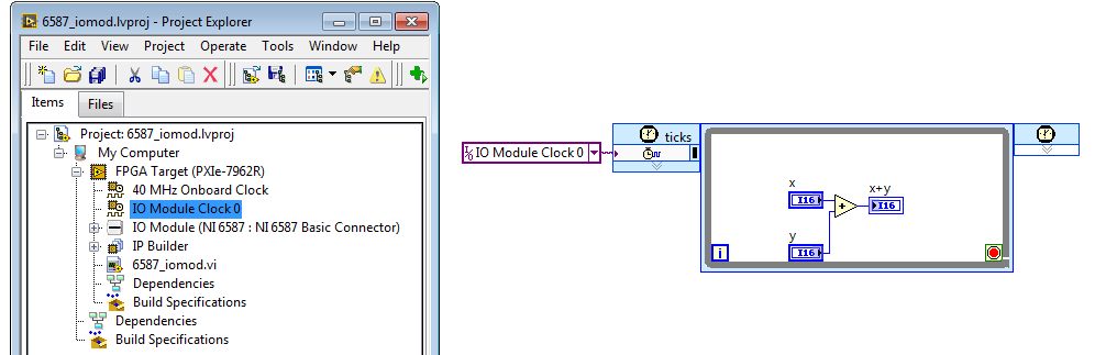
I have a PXI fpga 7962R module and or 6587 adapter. I want to use the external clock to set up a simple Adder xilinx Ip core. I have the e/s 0 clock input an external clock of 20 MHz with 3 V pk to pk. I then attached to single loop timed cycle and fpga clock allow VI and set up my IP core inside the loop. I haven't used the fpga disable vi since I want continuous running vi.
now the project, but on the spot and I don't see any other except top 40 MHz clock being implemented. At the end of the compilation, I received an error which fpga and host could not communicate. the clock z not connected or is nott generated according to specifications. What could be the problem?The project you attached had not included in FPGA vi so I am unable to tell if you were using the IOModClipClock0 correctly.
Anyway, attached is a draft that has the IOModClipClock0 added to the target, and an FPGA VI, who uses it to run in a single clock cycle logic loop.
-
the substitution of variable in the profile of stimulus Editor
Hi all
I want suggestions on how to do it.
So I put the system definition for one of the signals as model Output1--> channel 1--> PXI FPGA AO1 user
Generally, the model output has controls the FPGA. However, I would like to substitute the output signal to another value to test a few flaws. I tried to substitute in the profile of stimulus Editor, but it would not work (for obvious reasons). I wonder what I can do to substitute the value of another signal that remove the mapping of model output 1 for channel 1 user whenever I want to test this fault.
Thank you.
Great question!
If you use the new editor of profile of Stimulus in 2011 VeriStand, you can perform insertion for lack of software of a sequence in real time using a set of special functions, fault, and clearfault. Fault function allows you to activate a software problem a specific parameter is mapped to a string of system definition (condition it is faultable) to a specified value. This replaces any source can have this channel mappings. To clear the fault of software, call clearfault on the service.
You can call these functions directly from the Expression. Here is some help on these and other features, you can call in a detailed sequence.
For example, imagine that you have the following sequence and ao0 parameter is mapped to the string of PXI FPGA AO0 system definition. This sequence when run would fault the AO0 PXI FPGA channel to the value - 10.0, wait 5 seconds, and then clear the fault on AO0. If the fault is active, all mappings are substituted, and any attempt to set the channel failing of the workspace will also fail. When the problem is resolved, any source mappings will affect again.
IMPORTANT NOTE: There is a bug in VeriStand 2011 which prevents a sequence of faults in real-time completely a channel if no other channel is currently failing in the system. The solution is to open the software tool Fault Manager of the workspace and the fault of some channels dummy, as a channel not used user, before running your sequence.
- MySequence.nivsseq
- Parameters
- AO0
- Code
- Setup
- Main
- Expression: fault (ao0,-10,0)
- Expression: Wait (5.0)
- Expression: clearfault (ao0)
- Cleaning
-
I have a PXI FPGA RIO of 7133 card. He is seen by MAX but not available through 'my computer' in a project. The card may have been moved to a different location PXI after initial installation. Any suggestions?
The problem disappeared after uninstalling the drivers PXI-7833 and module FPGA and then put it back. All cards in the PXI chassis (which is full) are now recognized in MAX and the 7833R appears as a target (formerly it does not appear as a target).
-
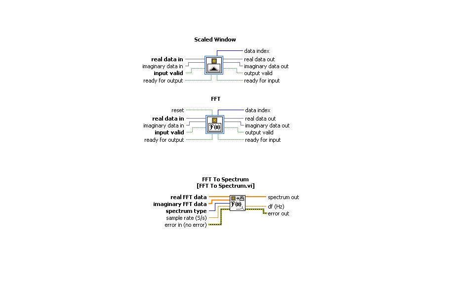
Using FFT to palette spectrum Subvi Interface of FPGA functions
Hello
I use the card PCI-5640R and PXI-5600. I want to use the "scale" and "FFT" exspress screws to the range of functions 'Mathematical FPGA and analysis' in my VI "FPGA VI" and "FFT spectrum for '"FPGA interface"in my"host VI.
A poster of the code examples in which these three subVIs are used can.
Thanks in advance.
Kind regards
Rashid
Hi rachid,.
There are two examples of delivery here: LabVIEW 2009\examples\R Series\FPGA Fundamentals\Analysis and Control\FFT\
Jim
-
Hey,.
It is sort of a basic question, and I don't know how at the height, I'm on the vocabulary of LabView FPGA. I did a machine States that performs a task, and I want two of these state machines is running at the same time. So, I created a Subvi with the state machine and placed two calls to them in the top level VI.
The problem is when I run the VI of highest level in interactive mode, the initial contributions are locked, and subsequent changes to the entries does nothing. So, basically there is something I don't understand. I imagining me signals propagating VI of highest level for two instances of the subVIs instead of the initial values being stored.
What I am doing wrong?
Thank you
Kevin
Hello kevin.key,
The difference between the two parts of the code that you fixed is that the code in the while loop will run several times until it stopped while the code without the loop will only run one and then stops.
Your Subvi begin values based on the values of input passed your top VI. These values will be updated every time your Subvi is called from your albums VI. To do this your top VI has a loop for continuous data and your Subvi should independently of your albums looping VI. The reason why the values in your front panel are not getting updated is because there is no loop in your top VI. If you include a loop that values will update each time the loop runs, which occurs only after the entire interior of the loop ends, including the Subvi.
If you have access to a computer with LabVIEW on it try to start live using the run culminating to see the behavior of your Subvi.
-
PXI data transfer between OTN and FPGA
Hello
I have a DAQ card in my PXI and a FPGA 7813R map.
The problem is that I send sample waaveforms of the data acquisition card to the FPGA card (which only has digital i/o) to launch my control on the FPGA. When I generate a sine wave of 50 Hz in the OTR to simulate a measured signal and send it to the FPGA through the controls in the Panel before (http://zone.ni.com/reference/en-XX/help/371599G-01/lvfpgaconcepts/pfi_data_transfer/) the signal happens on the fpga is much slower than 50 Hz indicating this folding is (it takes too much time to send the data). I tried to use this method of data transfer because my control requires only the more recent data, but it also has a phase lock loop that requires the data arriving at least resemble the original signal. Another criterion is that the control to data more up-to-date as possible. I know there is another option of the use of DMA FIFO, but I use it because I thought it would take more time to send the data, because each value must be sent.
My questions are:
I go about it the correct way? I know that there is the FPGA cards with analog inputs. I buy one it is because I have a large amount of differential analog inputs (20 +)
Is there a quick way to transfer data to the FPGA. (I have converted all the FXP data before writing to the FPGA)
Hi Jagwa,
You should not have to synchronize the RTOS loop that written information and the FPGA VI which is read. Instead, you can simply use a FIFO. In RT, you can write all the data points for the FIFO, and then you can extract them one at a time on the FPGA VI and use them as needed to control functions. In this way, the only time you need to worry about stopwatch the FPGA VI to get out the data to mimic 50 Hz.
Kind regards
-
periodic waveform generation complex FPGA (PXI-7852R)
I would like to create a complex periodic wave (digital) with my PXI-7852R.
After checking the article here on the generation of periodic waveform with cRIO and then for a few hours trying to get this software to work on my fpga (PXI-7852R) I'm not much closer to making it a reality.
I bet that someone with more experience could some conversion not fast enough... Notice to lovers?
Thanks in advance!
-
Change the Data Type to node e/s on PXI-7841R FPGA
I would like to change the data type for the node FPGA of e/s on my card FPGA 7841R (simulation). So far, I have raw data (I16). I want to test something with the calibrated data (FXP).
The cRIO, you usually go to the properties of module to change the calibration mode...
I searched 7841R documentation and could not do any weather information this calibration mode was also available on this map.
Any tips?
Vincent
The new maps in the series R offer node fixed point IO (for example, the SMU-7858R), but as mentioned all the old PXI based cards R-series offer only modes of measurement I16.
Page 22 manual R series is about how to do this conversion: http://www.ni.com/pdf/manuals/370489g.pdf#page=22
Specifically, it notes that you can calculate the voltage by (output Code I16) * 10.0V / (32 768).
Even if this can use FPGA resources, it records the host do the same conversions. RT old target with slow processors doing the conversion of I16 or FXP to SGL on the FPGA has saved a lot of time CPU


Maybe you are looking for
-
Pavilion: laptop enter your password administrator or power on password
My phone asks me to enter the password administrator or power on password. Help, please.
-
How to get the properties of an instance of VI its own SubVI Refnum
Hi all Through the "diagram" of a given VI property, you can access the array of references to all the SubVIs that it contains. (Purpose of scripting).But I can't understand how an instance of a VI (in another diagram VI) might return to his own Subv
-
Error in OUTLOOK Express 0x800CCCA9
-
HP Pavilion dv6-6c40se: lost recovery disk
My hard drive recently failed and I replaced with a new one and I do not have the recovery disk, what shall I do?
-
WEBSCAN tool for HP Photosmart 7510 e-All-in-One - C311a
HP Photosmart e-All-in-One 7510 - C311a, windows XP SP3 I try to scan from Control Panel or a pc, but get the error message "scanner communication cannot be established. I'm used to be able to do, but now does not work. At the same time, I got the c