Read an absolute encoder in cRIO 9076
Hello
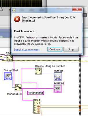
I try to use cRIO 9076 and NI 9401 to read an absolute encoder (http://www.gpi-encoders.com/PDF/A58.pdf). I hope that it is possible. Please can someone advise if there are any example or a tutorial that explains how I can deal with the digital input data to get an output of numeric position? Thank you.
Hello:
Are you using the A58-12 encoder? (It's the only one that looks like it will work with the 9401). If so, it returns data using the series SSI Protocol.
You will need set up an output clock and the input of the 9401 SSI data line. For the reading of the data, there is an example of FPGA SSI on the community related to this knowledge base Article.
Hope that helps out!
Tags: NI Hardware
Similar Questions
-
Entry of absolute encoder PWM w / 6008
Hi, I'm quite new to the DAQ world so please be easy on me.
Well basically, I have acquired a free 6008 and want to use it to track the absolute deviation of angle of a device I have.
My scope involves the use of a labtab (USB only), as well as a range of measurement 0-90 degrees with an accuracy of 1 degree at most.
So I came to the conclusion that I have to get an absolute encoder.
Watching the encoders and their respective exits, I found the following: SSI, Linear Voltage (0-5 Volts) and PWM
I have falling SSI my list because it seems a PCI data acquisition card is a requirement, and the linear voltage is all simply not precise enough, because the encoder outputs (0.056 volt/deg) and the 6008 can be read only with accuracy intervals (0,138 volt). Which means (2.484 degree/interval), I think.
in any case, the last style of output that I found was the PWM signal.
The encoder http://usdigital.com/products/encoders/absolute/rotary/shaft/ma3/
If I have good outings (at intervals micro-sec 1026), where the duration of the pulse is the position of the encoder. (1026 counties/revolution).
So I guess I have to be able to read the pulse of the order (1 micro-sec) for (1 head).
My question is whether or not the 6008 is able to acquire the data for my use in LabView.
Counter the 6008 says its able to detect more than (0,1 micro-sec) pulses.
Does this mean the 6008 so capable of doing the job?
Any help is grateful, as I have very little experience with LabView or DAQ instruments.
Thank you.
It is a limitation just to the meter of a USB-6008. What you describe with 2 counters is actually very close to what we do for measures high frequency on our complete recommended counters. The pulse actually measure that requires only one meter on our E-series, M-Series devices, meter Timer and X-series.
In regards to the analogue output of the absolute encoder, I think you should be ok with the resolution. The output of the encoder is 0 to 5V. The typical accuracy on the 6008 for this interval is 4.28mV for differential connections. Step for each degree size is 5 /(2^10) = 4.88mV. Thus, it seems that you will be able to get a precision less than 1 degree.
If you need better accuracy or would prefer to make the PWM output type, I would look at our M-Series USB for a portable data acquisition solution. Let me know if you would and I'll give you a few recommendations.
Regads,
Paul C.
-
cRIO 9076 Unable to Detect physical channel
Hi all
I'm currently trying to acquire data using NOR cRIO 9076 controller integrated, but I am unable to create virtual channels using DAQmx. My situation is summarized below.
Material:
NEITHER cRIO 9076 integrated controller RT
NI 9205 analog input module
E/s digital NI 9403 module
Software:
LabVIEW 2011
Compact-Rio 4.0
MAX 5.0
NOR-DAQmx 9.3
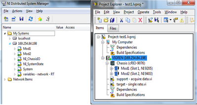
All channels of the C-series module and chassis are visible in NOR Distributed System Manager and Labview Project Explorer.
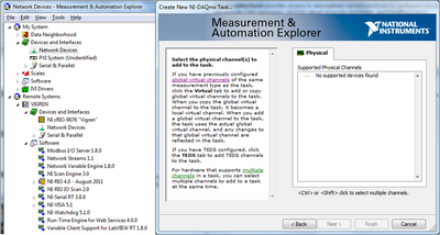
But when you use MAX to create a new task DAQmx, I can't detect the physical channels. The two NOR-DAQmx in Labview and right-click to headquarters of the MAX data to create NI DAQmx task / Global Virtual Channel give the message "No. supported Devices Found."
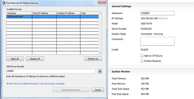
In addition, material also doesn't seem to appear under "devices devices and Network Interfaces. When comes to "find NI DAQmx your network equipment", he stated that "no devices were found. The controller was named "VIGREN. Detect manually by using the host name and intellectual property also failed to detect.
My question is:
1. How does the PC detects the chassis and modules, but when it come to NI DAQmx, it does not detect the physical channels? What is a software/hardware or network junk?
2 not compatible with NI DAQmx RT 9076 cRIO controller? And that's why Scan Interface or Interface FPGA used instead? In light of the seamless functionality, I prefer to continue OR DAQmx to configure my acquisition of data.
Thank you.
Hi Vigren,
I think you misunderstand some of the concept here.
cRio is a real-time system and is not a DAQ board that you can not use DAQmx with it.
You can refer to this link for discussion for more information
http://forums.NI.com/T5/Multifunction-DAQ/cRIO-9073-compatibility-with-NI-DAQmx/m-p/1194163#M58721
You can use the scan or FPGA to purchase.
TuiTui
-
Why the new cRIO-9076 does not support the scanning engine?
I spec'd a new chassis cRIO-9076 spiffy but learned that, despite its impressive capabilities, it does not support the analytical engine.
I'm curious as to why this is. I hope that this is not an indication of support OR away from the scan engine and perhaps NSV technology as well.
OK, uninstalled and reinstalled OR RIO 4.0 and now all is well, guess it was just one of those inexplicable installation problems.
-
Combine the cRIO 9076 and cRIO 9081
I have two controllers time real FPGA: cRIO 9076 and cRIO 9081. Due to not having the latest version of LabVIEW (2011), I am unable to use cRIO 9081. CRIO 9076 not having only 4 slots for modules, I am using cRIO 9081 as a slave just to add more modules on its machines slot. Will this work? If so, how can I connect the cRIO 9081 to cRIO 9076. Any suggestion is appreciated.
Hello ExcelX,
Unfortunately, there is no meaningful way to interface with the 9081 without going through the correct versions of LabVIEW (at least 2011) and NOR-RIO (at least 4.0). It does not have windows, so you could theoretically it boots into Windows and plug a monitor on it, but you wouldn't be able to run any code on it.
You can download the demo version of LabVIEW 2011 and use it with your 9081 for thirty days. But I recommend you just upgrade to LabVIEW 2011 - the 9081 is a powerful (and expensive) CompactRIO.
-
Transfer TDMS file cRIO 9076 PC locally using Labview code problem
Dear all
I use LabVIEW 2013 with cRIO 9076 for datalogging PDM.
I try to transfer the logging queue (.tdms) cRIO to the computer via the LabVIEW FTP software. The transfer is OK but computer I can't open the file-68007 error.
It's ok when I copy the cRIO on computer file ( ftp://192.168.2.102 and manually copy the file)
How can I fix the ploblem and LabVIEW FTP allows us to trnasfer file.tdms?
Thanks and greetings
Luong.Tran
This might be useful:
http://forums.NI.com/T5/real-time-measurement-and/TDMS-files-corruption-when-using-FTP/m-p/2331550
-
How to read a quadrature encoder, using a PCMCIA card from 6036E?
Hello
I 6036E PCMCIA card and I want to read a quadrature encoder.
I must not use the z index.
My version of Labview is 8.5.
When I try to use the DAQ assistant and choose the option 'angular position' I get the answer that no supported device were found.
What should I do?
Thank you in advance,
Fotios
Hello
Card PCMCIA-6036E has a STC chip that does not support the encoding position because there is no support of Z. It must be resolved in the software and using the edge counting.
Some info on E-cards and quadrature encoding:
http://zone.NI.com/DevZone/CDA/tut/p/ID/4623
http://zone.NI.com/DevZone/CDA/tut/p/ID/2879
http://zone.NI.com/DevZone/CDA/EPD/p/ID/1427
/ Klas
-
Encoder FPGA Crio SSI Protocol
Hello everyone
Everyone works with encoder SSI and Crio FPGA Protocol? I wrote a simple program that try to apply this Protocol on Crio FPGA, but I get the chaotic data. I use a TTL-rs422 converter to transform (422) signal at the TTL for Internet signal high speed digital NI9401. Could someone help me? any suggestion?
Thank you
Francesco
Hi all
I solved my problem. I am able to read the angular position of an Eltra encoder with SSI protocol using labview FPGA.
Thanks for all the help
Francesco
-
Connect an SSI absolute encoder to a DAQ card
Hello, everyone
I try to connect four encoders of DAQ cards. Two of them are in quadrature encoders and the rest two absolute encoders. I'm guessing that connects the two quadrature encoders to both timers/counters on the card. But what of the SSI absolute encoders? Anyone can give a clue? Thank you very much.
Either way, I am using PCI-6251 and xPC Target.
Pengfei
Hi Pengfei,
If you do not use our driver so I don't know if this is supported, but here's how I would do it using DAQmx...
According to the features of calendar defined page 10 specifications page, 500 ns is the minimum period for almost all relevant parameters:
Period of the CLK line semi
Time between the CSn and the first edge of the clock
The CSn pulse width
Well, it makes sense of the clock of your 2 MHz. You need produce waveforms of the following two, each cycle would be clock to 18 bits of data (12-bit encoder and 6 status bits). The total duration of the cycle ends up being long 38 samples and would take 19 microseconds to execute (if updated to 2 MHz).
CSn 1 0 0 0 0 0 0 0 0 0 0 0 0 0 0 0 0 0 0 0 0 0 0 0 0 0 0 0 0 0 0 0 0 0 0 0 0 0
CLK 1 1 0 1 0 1 0 1 0 1 0 1 0 1 0 1 0 1 0 1 0 1 0 1 0 1 0 1 0 1 0 1 0 1 0 1 0 1
The actual binary data to write to the card depends on what lines you use. For example, if you use p0.0 to CSn and p0.1 for CLK, table you would need to write would be the following:
3 2 0 2 0 2 0 2 0 2 0 2 0 2 0 2 0 2 0 2 0 2 0 2 0 2 0 2 0 2 0 2 0 2 0 2 0 2
The bits of the U8 number correspond to the 8 rows on the port.
You will need an example of clock for your task source. I suggest to use Freq Out on the 6251. In DAQmx, it is programmed in the same way as a meter output. You would set this up as a continuous meter to 2 MHz output. Indicate on your task to use ' / Dev1/FrequencyOutput "as the sample clock source (not necessarily Dev1, but regardless of the name of your device).
You would physically signal port thread 0 CLK in PFI lines and use it to sample a DI task so that you can read back your data. You can enjoy on the falling edge of the CLK to allow 500 ns for the value to be set (the maximum duration of your sheet is 394 ns). The only drawback to this is that you are not sampling the parity bit, but apparently not that it is a problem unless you plan to use it.
Once you get the bits, you must translate that into an actual position. When you call DAQmx Read, you will have an array of values. The first value of each cycle is a disposable (look at the waveform to see why). The next 12 items of any cycle would be the 12 data bits, next 5 bits of State. As I mentioned earlier, the parity bit would not be sampled because of the decision of the sample on the falling clock edge (again, you can refer to the waveform to see why this is the case).
You'll want to convert the 12 data bits of the table in a single 12-bit integer, then multiply by (360.0 / 4096) to get the position in degrees. I don't know what development environment you use, but this type of data manipulation must be achievable. For example, LabVIEW has a Boolean array of numbers feature that would be very helpful here.
I hope that helps!
Best regards
-
Hello.
I have problems to make my cRIO to control my Keithley 2400. I have two devices connected via an RS-232 cable. I can find the Keithley by using MAX in serial & parallel options and it indicates that the device is functioning properly.
I open the Panel Test VISA and in inputs and outputs
Writing: * IDN? \n
Return data : write operation (* IDN? \n)
No errorRead: * IDN? \n
Return data :
Read operation
ErrorVISA: (Hex 0xBFFF0015) timeout expired before the operation is complete.
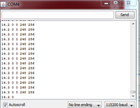
KEITHLEY\sINSTRUMENTS\sINC.,MODEL\s2400,4049517,C32\s\s\sOct\s\
s4\s2010\s14:20:11 / A02\s\s/U/K\rWhy is - it gives me an error of timeout and then give me the expected data?
I'm new to series of programming and always try to get the basics.
Thank you in advance.
Roth
Looks like you have set for the character of improper shutdown. The returned string is a newline (\r) and your program can be programmed for a line (\n). Modify your code or change the setting of the instrument.
-
Series read several sensors (Encoder + accelerometer)
Hello
Im working on this project where demand encoder interface and accelerometer to the marker. I tried to read the serial data and use it to establish a curve (real time).
Problem;
1. whenever I run it will be always pop out error
2. There is delay in labview signal when I try to read through real-time graph.
Thank you
Effendywoo
-
cRIO 9076 HAVE sampling problem
Hello
I have a question about the NI 9223 samping rate in our 9076 cRIO system.
Given that hopefully samping at a rate up to 500 K or 1 M, we are now using the user controlled sampling I/O.
Right now, we are sampling 500 k (2). But I got a number of cycles of 99 graduations (about 2.5us) for sampling only node.
Should I wait so many ticks for block sampling? I did all this trouble?
Thank you very much!
Hi hang up,
Looks like you're indicating the rate of loop for the entire while loop, in that you and not just a specific part of the code. Because you have your loop timer, controlled by a front panel object, it is possible that compiled code, but if you change the time of the loop to a low value, the code cannot complete in time. I suggest that you conclude the acquisition you are trying to do in his own loop so that it can operate at full speed.
In addition, in order to obtain the complete acquisition of MECH. / s, you're going to need architecting your acquisition. I encourage you to check the code example in our search for the NI 9223 user controlled II example a composition for the best way to get these maximum acquisition rate. In addition, depending on how you're going to export these data from the FPGA, your controller ART may not be able to handle a throughput of MECH. / s.
To answer your question specifically, I suspect that because you try to make a wide loop in a short period of time, the FPGA cannot complete the task in time, so it uses by default a rate that can be better managed. For the control you are looking for, I encourage you to move your application to architecture in the sample project to get the behavior you want.
-
Hello world
I use a module in series or with cRIO 9870 9014. I have need to acquire analog data with the GPS data and lang + long for each data point.
I am able to get to the host vi gps data, but I am confused about the acquisition rate. I was curious and place a control on front panel to watch the gps in my RT vi data and I see a lot of spaces. (photos attached). I watched a lot of good examples on gps with the readers of visa, but since I'm on a cRIO with a TCP connection, I don't know how to process the data of succession on the controller.
Can anyone help me please with ideas to use the module straight series.
Thank you
Tamanna
Since it is a serial connection, you need to be constantly read the 9870 on the FPGA. Even if your gps only updates once a second, that "update" has strings of unsigned 8 bit integers representing all of your characters - each read one of these U8s, seize only if you read at 1 Hz, will NOT correct data.
So... Read on the FPGA continuous, faster better and passing in a FIFO to pass off to the host so that you can decipher your data. You may need to adjust timeouts on i/o reads. Definitely take a look at the examples in the example for communication finder series with this module.
And... as a diagnosis... you should be able to do this easily plug into the port series to your controller and use the controls VISA ON THE HOST RT - ethernet connection has nothing to do with it.
For diagnosis, the indicators more the better. Let me know if you more specific issues.
-
Hi all
I tried in vain to issue his coded speex . It's really frustrating.
I save the audio microphone and encode using the speex codec. The rate used is 16 kHz when I use speex and I can't change that. I want to play this audio recorded. With the help of sound object I can't play this audio well, because it requires the audio at 44.1 kHz.
"How can I play a sound which is coded and stored in ByteArray speex?
I have searched for related articles or topics, but did not. Help, please!
Kind regards
Pat
If you want to use the generation of sounds, you must provide to 44 kHz stereo samples. So if you have a speex bitstream, you must decode in ActionScript and frame rate to 44 kHz. This is possible, but a lot of work.
Another way to play the audio speex is to listen from Flash Media Server. Flash Player, decoding and unfold audio speex, Nellymoser resembles.
Speex is playable in exactly in the same way as Nellymoser. A difference that Nellymoser supports several samping rate, while speex only supports supported the 16 kHz.
-
If this is true
 NTP synchronization is a big correction of the date-time on the boot. After starting, it adjusts the processor clock to account for drift. The algorithm has tolerance of error, but if you exceed this tolerance (i.e. If you're too far out of sync) it will stop trying to set the CPU clock to synchronize. Calling the Set Date & Time VI typically causes the clock to go beyond the tolerance of error algorithm. Is there a tolerance of error on the large correction also? I'm not able to get my system to sync on startup, so if the controller resets to zero, I'm wasting my time. Will there be a VI to query the server sntp in initialization and time setting here?
If for some reason, I get to work with NIST but not on our servers. So, I am dealing with our network again. Thanks for the help.
Maybe you are looking for
-
Can I use the FF logo on a t-shirt design? Or I would violate some sort of copyright?
I know, not really a problem, but I don't know where to ask... So I came up with this brilliant idea to create a custom design t-shirt with a few logos on this subject and I wonder if I would be violating some (c) if I included the logo ff on this to
-
PXI-6120 digital output frequency
Hello before that I have to post my question some technical information: LabVIEW: 2011. IO digital 8 PXI-6120. I read the user manual and search the Forum and there is no reference to the frequency of digital output (only for a meter). My question is
-
Significant decline in performance on the GRE tunnel after using cryptographic protection
Hi all I have two G1 RSR (1811 and 1812) who have a GRE tunnel between them. Without any encryption protection I received about 3.6 MB/s in regular transfers of Windows SMB. After using cryptographic protection of the tunnel I'm now only 2.7 MB/s tra
-
Cannot print the printer is off line with 14 documents pending.
Original title: Printing print HPrinterMy printer is off line with 14 documents pending. How can I get it online and cancel pending documents.