Read for the acquisition of data entries are overwritten
Hey there
I have a Daq reading input in a spreadsheet file
Data acquisition was told that one is supposed to have some time a loop around it and I cannot get it to run without one, so good
But my main problem is that it means that it replaces my written file each time that the loop repeats
He also asked me to choose the file to write in several times
How would I go about fixing this?
Thank you
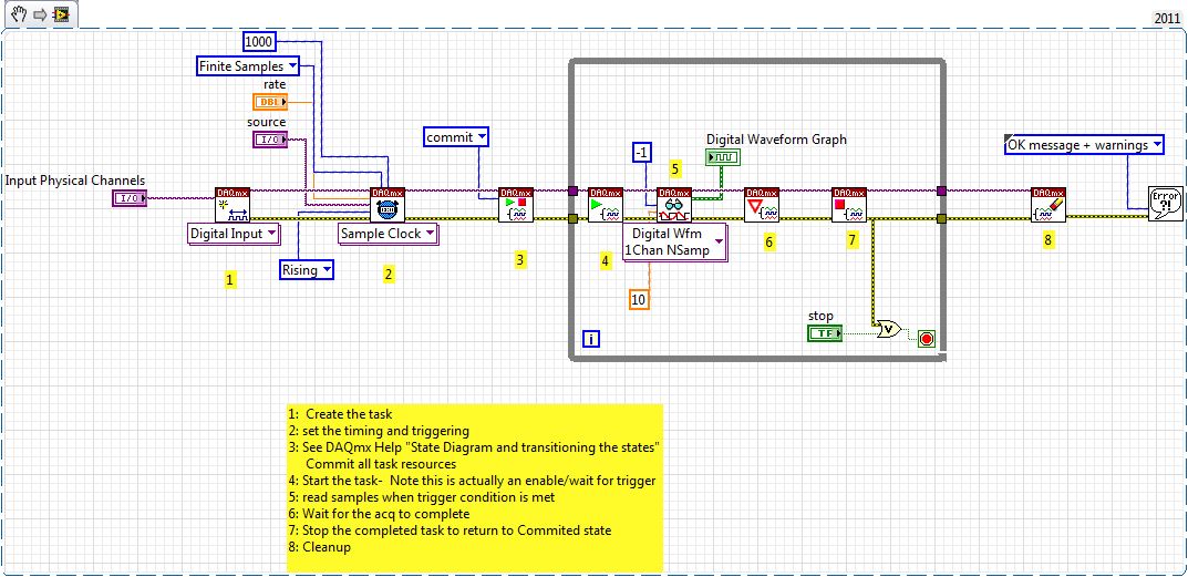
Yes, you can convert digital to the chain, check the attached VI. I recommend you to go through the basic materials of LabVIEW and also play with example of NEITHER which comes with LabVIEW. Remember not to use the attached example and the acquisition of data, always use separate loops.
Tags: NI Software
Similar Questions
-
Use two assistants for the acquisition of data at the same time
Hello
I want to read multiple data channels of analog inputs on my DAQ hardware. However, when I try to create two separate data acquisition assistants for each entry, it gives an error saying "is reserved for the specified resource. The operation could not be performed as indicated "." Can't use two assistants for the acquisition of data at the same time?
I have to add different channels in the same assistant DAQ? I tried, but I couldn't separate the data in different graphs.
How does this work?
Kind regards
Allard
You can't have multiple tasks of the same type (in this case inputs analog) on the same device. Just so having 1 DAQ Assistant read all your channels and separate your channels for individual transformation.
-
I have a PCI 6519 data acquisition card. I want to install it on the PC and use it outputs to control a robot. I have problems with the connections to the terminal block which is attached to the cable.
What type of connections I do for the acquisition of data PCI 619 card pins? What I have to give it to the ground and the CCV on the pins of the connector myself? What should be the value of the SCR I need to give to the PIN?
-
Restarting a task for the acquisition of data inside a For loop
Hello
I need iterate through my acquisition of data. Currently, I'm doing this through the creation, implementation and tasks for the acquisition of data inside a loop For which is iterated according to the needs of compensation. Unfortunately, the creation of these DAQ tasks slow down my code.
I would like to be able to create the tasks outside the loop, pass them in and revive the tasks at the beginning of each iteration. Is there an easy way to do this?
Otherwise, is there a way to make the standard DAQmx digital startup trigger trigger several times (so that it starts each pulse data acquisition in a long pulse rather than just the first pulse train)?
Thank you!
-Evan
I whent before and created this example for you (and many others.)
-
We send 5v data acquisition using a voltage generator. Hook us it up to a voltmeter and see 5V. When connect us the generator voltage to a valve "normally open" parker, the voltmeter indicates .14V. It seems that when we connect the two sons of the valve for the voltage generator, the son act as pattern. We want to control the voltage flowing to tap through Labview. We checked the wires to the valve and they work very well, because if we send a constant 5V since the acquisition of data and put ashore, she, the voltmeter indicates 5V. Someone knows why the son act as pattern and low blood to .14V?
nsatpute wrote:
Our data acquisition is NI USB-6259. The valve requires only a 5V max and our DAQ provides up to 5V. However, after connecting the valve to the acquisition of data, the grave tension to almost 0. We start from the principle that the son somehow act as the reason, but we are not sure if this is the case.
The question here is not how much voltage the valve wants, it's the current needs of the valve. The 6259 can put only 5mA via an analog output. Your very likely tap needs much more than that. If you need to add in an amplifier circuit that can supply more current to operate your faucet.
-
Calendar for the acquisition of data on the USB-6212
I am putting together a sound teaching laboratory. The basic idea is to send a pulse signal that powers a speaker, and then the acoustic signal travels down a waveguide where it is measured with a microphone and sent to a data acquisition. One of the important things here is that it is possible to measure the time of propagation of sound waves, so I need for data collection to occur at a time determined with reference to the sound output pulse. I tried with a sound card, but there are number of milliseconds of random jitter between the writing and the reading of the sound card.
So, I was watching the USB-6212. On paper it seems ideal: 2 outputs and lots of inputs. What I understand, it is possible to trigger analog outputs and data entered so that there is no jitter synchronization between them. The only question is this: I was thinking about using 2 analog inputs: a reference which collects through a microphone/speaker system to serve a normalization to the second chain that collects through waveguide (see diagram). The thing is that I need the "timing" on the 2 analog to be consistent and a jitter free so that it is possible to compare the phase of the signals that I collect. This will be possible using this data acquisition system, given that the ADC is multiplexed between the channels? There will be a delay between channels 2 and if so it will be known and deterministic?
Thanks for your help...
Ben
Hi Ben,
Cool application! To answer your question-Yes, there is a delay, and it is deterministic. Something to note about the 6212 is that your rate of multiplexing will be determined by the clock to convert. The clock to convert will operate at the faster pace of the device more 10us *. In the case of the 6212, with Max sampling rate of 400kS/s (aggregation), your pulse will produce each ((1/400,000) 12.5us + 10).
* 12.5us converts to 80 kHz, so at that point there, convert clock it simply runs at 1 /(aggregate rate). So to sum this up:
From 0 to 80 kHz: there is a lag multiplexing 12.5us
From 80 to 400: there is a shift of /(aggregate rate) 1
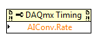
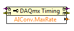
In addition, you can also set this rate through the DAQmx driver. "You can just use a property DAQmx Timing node' more' converted ' rate (or rate Maximum to determine the max).
If it's a problem, I advise to use a device with simultaneous sampling - let me know if you have any other questions. Take care!
-
Hey Hey everyone
I was looking for an example for two-channel oscilloscope virtual using e/s all-in-one of the 14 bits of NI DAQ USB 6009. I tried to research for example BOF time division or s/div for 1 second, 5 seconds, 10 seconds. but was shocked to find that there is no reference for it. The range of oscilloscoper virtual
Minimum - 10 micro s / div maximum -10milli second div but there is no example for 1 second / div or 5 seconds / div... If anyone can guide me. I'm new to labview environment.
This is the oscilloscope two sample obtained from google search. is there material limitations. ?
I'm working on continuous 4-channel data acquisition data acquisition using niusb 6009
The sampling frequency is sufficient for any desired s/div. The sample rate is 12 ksamples / s per channel, so if that meets the Nyquist criteria for the input signal, you can capture it. The number of samples has no effect on that with the exception of the amount of the signal you acquire. Your chart is not stable, if you do not trigger the acquisition. Even as real significance, therefore your emulation seems actually successful.
-
standalone application for the acquisition of data using the NI DAQ card
I did a stand-alone application in labview GUI for data acquisition and processing of the signal. If I have to run this application in any other computer which should be all installed software other than the labview runtime engine... CD DEVICE DRIVERS OR alone must be installed or do I have to install any other software of data acquisition using the data acquisition card OR?
Thanks and greetings
You need only the racing of the engine, the device for the device drivers, maybe need pilots VISA if you make serial or something of this nature, you may need the channels or tasks created in the measures OR and automation if you created the it.
There may be other things you'll need depending on what you include in your code and what tool kits that you have installed.
-
Hi all... I learn LabVIEW since few days.i want to acquire a signal of pc6251 of acquisition of data and perform fft it can u people please help me? Thanks in advance
If you do only use LabVIEW for a few days, you should get familiar with it first by looking at some of the resources available here. After that, you can watch heredata acquisition.
After reviewing these documents, you can post back with any specific questions.
-
Sensor with Signal conditioner for the acquisition of data NI 6009 force
Hello
I currently lead a unique test by using a pendulum. Currently, there is a rotary potentiometer measures the rotation of the shaft and a force sensor to measure the impact. The Rotary potentiometer and data acquisition work like a charm in SignalExpress but I currently have problems with the force sensor.
The installation program:
Sensor Signal conditioner box-->--> DAQ (analog input 1 & corresponding to the ground) by force.
In Signal Express, when I "Add Step" process - should I choose "Acquire signals--> DAQmx Acquire--> analog input--> [voltage? The force? Custom?]
Thank you 1 million,
AW (big noob)
Hi a_wishart,
I don't think that the evaluation of Signal Express version is the reason for which you get this error, see the related document, there are several possible causes of this error.
http://AE.natinst.com/public.nsf/Web/searchinternal/485201b647950bf886257537006ceb89?OpenDocument
N
-
Components for the Acquisition of data for a Sub miniature sensor
Hello
I'm looking to acquire the data of two simulatneously cells (T4 - 100 L Measurement Specialties ELFS) load Sub miniature. The FS it out 100 lbs to 2.83mv / lb. I already have LabVIEW 8.2 and have acquired data using an analog I / 0 but my signal was weak compared to the noise in the system. I am a high speed data capture because the application that I use has an impact.
My question is: what the amplifier signal conditioner and the DAQ combination would be the best for this aplpication?
Thank you
Scott Kramer
Hi Scott,.
Welcome to the forums EITHER! Looks like you might be interested by the 9237 bridge and strain measurement Module. The 9237 comes in a USB, Ethernet, or Wireless channel, or as a stand-alone module for use with a cDAQ chassis. The 9237 offer a 50ks/s/ch sample rate, up to 10V of internal excitement which should reduce the noise from your system. Based on what you mentioned, it's the product I would recommend - you can find the manuals on the links above to verify that it meets all your needs. There are additional specifications that you need?
-John
-
Linux drivers for the acquisition of data USB-6229
I would use a USB-6229 with Linux and support driver selection guide said that this model is not supported. However, the 6218 and others are supported. Is it possible to use 3. 5B pilot defined for a USB-6229 with reduced functionality? Is it possible, with some basic Linux knowledge codification driver of change 3. 5 b drivers to work with a USB-6229?
Kind regards
Craig
Hi Craig,.
That is right.
Best,
-
Adjust the voltage for the acquisition of data in C range
Hello
I'm trying to run a USB-6211 in C++ and I would like to change the voltage range of (-10V to10V) to (-1 v to 1 V). Can I just change the minVal and maxVal in DAQmxBaseCreateAIVoltageChan call? Or I have to adjust the device itself and recalibrate.
Concerning
Simon
Hi Simon,.
Thanks for your post. You're right, you just need to change the minVal and maxVal in the call to DAQmxBaseCreateAIVoltageChan. The DAQmx base driver supports the hardware of the range you select, do not re - calibrate your device to adjust the material.
Kind regards
-
I am interested in buying a probe voltage signals. I use NIDAQ S-series PCI-6143. My requirement is that I need to acquire only above a certain level. I tried to use the task of triggering NIDAQmx but it fails to give error-200077 code. and the description says im allowed to select only digital edge trigger.
Help, please.
Thanks in advance
HI Maria,
in fact, the message you get is itself, as NI 6143 specifications indicates that this card supports just digital triggering. You will find the list of material of the series that supports analog triggering here: that S-Series (61xx) Support analog devices triggering?, or you can use an external circuit as comparison of analog signal.
Kind regards
s9ali
-
I want to integrate the ANSI C sample program ReadDigPort - ExtClk.c in my own big package.
I want to use the internal clock of the BNC NI USB-6259 (.. 80 kHz 120 kHz).
In the document:
High speed M: Series Multifunction DAQ for USB - 16-bit, up to 1.25 MECH built-in BNC connectivity. / s,.
is written:
Or sample DI source clock: Any PFI, RTSI, HAVE sample or convert clock, AO, Ctr n out internal and many other signals sample clock
The digital subsystem doesn't have its own dedicated internal synchronization engine. Therefore, a sample clock must be provided another subsystem on the device or from an external source.How can I use internal clock case OR USB - 6259 BNC for the acquisition of digital data in my own big software?
With what other subsystem on the device can generate a source of the clock? How?It is possible to set a clock on an internal counter (for example ' Dev1/ctr0"):
Creates channels to generate digital impulses that define the freq and dutyCycle and adds the channel of the task that you specify with taskHandle.
DAQmxCreateCOPulseChanFreq (taskHandle, "Dev1/ctr0" units, clockName, idleState,
initialDelay, freq, the duty cycle); worksBut it is not possible to drive this internal clock to a terminal (for example "/ PFI0/Dev1"):
DAQmxErrChk (DAQmxCreateCOPulseChanFreq (taskHandle, "/ PFI0/Dev1", clockName, units, idleState, '))
initialDelay, freq, the duty cycle); does not work: error DAQmx: measurements: type I/O of the physical channel does not match the type of I/O required for the virtual channel you create. Name of the physical channel: PFI0. Name of the virtual channel: clockThe sample clock source can be derived from an external terminal (for example "/ PFI0/Dev1"):
Sets the source of the sample clock, the sample clock rate and the number of samples to acquire or generate.
DAQmxCfgSampClkTiming (taskHandle, "/ PFI0/Dev1", maximumExpectedSamplingRate, DAQmx_Val_Rising, ")
DAQmx_Val_ContSamps, bufferSize); works. Acquire or generate samples until you stop the taskBut it is not possible to derive the internal counter of the clock (for example ' Dev1/ctr0"):
DAQmxCfgSampClkTiming (taskHandle, "Dev1/ctr0", maximumExpectedSamplingRate, DAQmx_Val_Rising,
DAQmx_Val_ContSamps, bufferSize); does not work. Error: Acquire or generate samples until you stop the task: make sure that the name of the terminal is valid for the specified device. See Measurement & Automation explore valid names of terminals. Property: Property of DAQmx_SampClk_Src: DAQmx_SampClk_ActiveEdgeSource device: Terminal Source Dev1: Dev1/ctr0Hi datafriend,
using what it says is correct:
Or sample DI source clock: Any PFI, RTSI, HAVE sample or convert clock, AO, Ctr n out internal and many other signals sample clock
The digital subsystem doesn't have its own dedicated internal synchronization engine. Therefore, a sample clock must be provided another subsystem on the device or from an external source.This means that if you do not use an external signal as clock you can use the sample clock to HAVE it on board or at the output of the internal counter.
There are also 2 ANSI C examples in this regard:
http://zone.NI.com/DevZone/CDA/EPD/p/ID/4485
http://zone.NI.com/DevZone/CDA/EPD/p/ID/4488
So in both cases you have to use a fictitious task you need only for the generation of the internal clock (HAVE or CTR)
Maybe you are looking for
-
I was on Redbox and accidentally disabled the part location function. How to re - activate this?
I was on the site of Redbox and clicked on DVD to find nearby and accidentally disabled the part location function. Anyone know how I can reactivate this function?
-
I've only had my netbook for a few days, so I'm not quite used to it again although I am well accustomed to Windows 7. I close the lid to activate the sleep mode, but it is difficult to wake the computer. I often hold the power switch to force a stop
-
I wondered about the difference between the Acer Aspire V15 Nitro Black Edition 4 K Model VN7 - 591 G-70JY and G-70TG VN7 - 591?
-
error code 2148204800 KB973917
Basically by train to run update KB973917, tried through the WSUS and manually, but fails every time. Event Viewer says it has an error code of 2148204800 No. Signature was present in the subject. I tried to stop the update service and delete everyth
-
Without appearing here no more
Like many other people posting today, I have no sound coming from my speakers or headphones. I can get sound from HDMI output. An update from HP has been installed the last time I used the computer. I have a Pavilion DV7 running Windows 7 64-bit.