reading of the sampling frequency of the NI9862
Hi all
I use a DAQ chassis with modules 9205 (analog input) and 9862 (NOR-XNET CAN).
I have a program to synchronize the modules for acqustion based on the attached example. My question is how to determine the rate at which data comes the 9862?
It seems to be double the rate of the 9205 when I set the sampling rate for the 9205 to 500 Hz.
Is there a property node or a method that I can use to find the rate? I looked in the manual, and it gives no information.
Thank you
Griff
griff32,
Baud rate XNET CAN occur in your database. You can also check using a property node. In the example, in the XNET Session property node, you can develop, select the Interface > baud rate. You can do a right click on it and change it to read and son in an indicator.
Alternatively, you can write to this property node to replace the transmission speed in the database. Baud rate must be compatible with the speed of your network. It also has a max of 1 mbit/s. If you want both to acquire the same amount of data, I would recommend changes in the rate of the analog input task or samples to read through.
Tags: NI Products
Similar Questions
-
DAQmx task Read DAQmx with sampling frequency of 10 Hz produced much too much data
I have a simple configuration with a strain of channel 4 OR-9237 amp holds a carrier of series C of WLS - 9163 (wired ethernet mode) - Details probably does not matter.
I used MAX to create a DAQmx task associated with which all four gauges samples. The calendar setting is "Scan Loads" is continuous sampling, 2 k buffer (read samples) and 10 Hz rate. I guess that this task would generate 40 data values per second - 10 for each channel.
I have a simple loop of reading using DAQmx Read.vi that works always (without any stimulation time). Playback is set to read all available data and then pump it into a table.
In the attached example, I also added a few words of debugging to stop the loop after N iterations.As the loop is programmed with a 0.2 second period, I expect each pass of the loop to read about 8 samples or 2 samples per sensor. Instead, I get hundreds each passage. It's like reading has substituted the sampling frequency specified in the task of the unit. I absolutely need data to be material to the rhythm.
Where have I lost?
Thanks Adnan,
I changed your example I selected 'Strain gage' entry analog and then lowered the minimum and maximum thresholds to +-1-2. What happens is that each other in the loop, I 2048 samples or zero samples. The display flashes a whole line and then it clears any other past.
In response to your second post, I understand that the loop cannot run quite right that I select. I think that, but at a sampling frequency of 10 Hz, I have to sleep on the software side for nearly a minute before I built 2 K samples.
I played with the frequency of sampling, assigning to various values from 0.1 to 10000Hz. The behavior is the same until I approach the high rates where available samples remains to 2048-4096 sometimes, the display becomes continuous.
Ahhh, Darn. Yet another search was this link that points to the root of my confusion. The 9237 can taste arbitrary rates using its internal clock. Duoh! I wish that the pilots are smart enough to warn you if there is a discrepancy between the selected sampling rate and capabilities of the device
-
How to find the sampling frequency to read the measurement file
Hello
I would like to find/extract the sampling frequency of a .lvm file.
Right now I am using the VI 'read file of measurement' and my data charge fine and all, but I need the frequency of sampling for certain calculations.
I know the header of the file .lvm that the sampling frequency is 1613Hz, but I want to get this automatic information from the open file .lvm.
Tried to find an express vi that could give me the answer, but I could not find a

I'm sorry if this question already answered, but I could not just to find the answer.
I hope you understand what I'm doing!
Thank you
Kind regards
Tommy
The timing is part of the production of signals information. Never use the functions of the Express, but you can use DDT to and convert to one of the data types of waveform. Waveform components then turns the dt.
-
How to specify the sampling frequency? Must use "measurement & Automation Explorer '?
I use to measure the input current analog OR cDAQ-9171 (chassis only location USB) and NOR-9207. I have 2010 NOR-installed DAQmx and LabVIEW.
How can I specify the sampling frequency?
If I use M & A Explorer to create the task, I can specify the flow rate (Hz) on the Configuration tab-> sync settings.
For the acquisition of data NOR, it is mandatory to use M & A exploring?
If I don't want to use M & A Explorer, how can I specify the rate (Hz)?
Hello
You can specify the sampling frequency with "DAQmx Timing.vi" located in the function palette DAQmx (read context-sensitive help on how to use wisely).
You do not have to use M & A exploring (MAX) to create a task.
A simple and quick way is to use DAQ Assistant (same configuration as in MAX) to configure your measurement.
Another is to use blocks of DAQmx function to manually build your application code.
In my experience Assistant DAQ is ideal for simple tasks (one measure), with regard to the more complex measures (synchronized the analog and digital inputs).
I tend to use function blocks because they give you more freedom about code execution.
Note: You can also build DAQmx code from a wizard configured DAQ task.
Best regards
Matej
-
Doubts about the sampling frequency when the production and acquisition
When the generation and acquisition of samples, the maximum sampling frequency is the maximum sampling frequency Council divided between the generation and acquisition of task number?
Thank you
Hi Houari,
You should read the specifications of your box DAQpad!
It is clearly said: entered analog = 200kS/s rate sampling, but analog output = sample rate of 300 s/s or even just 50 s/s for the hardware timing!
-
What is the relationship with the sampling frequency and number of samples per channel?
In my world, if I wanted to taste 10 seconds 10 Hz (100 s/ch), specify a rate of 10 and a number of samples of 100. This would take 10 seconds to return data. The task does not appear to behave this way. No matter what rate and the number of samples, I chose, I spammed with data at 1 Hz or more.
What I am doing wrong?
This problem is resolved by making a request for telephone assistance. It turns out that the minimum sampling frequency of the NI 9239 is 14xx s/s. I don't know why there is a minimum sampling frequency, but now I have to go to the next question discussed at this link:
-
Time interval in the output file is different from the sampling frequency
Hello
I'm a load at 1000 Hz. cell sampling I send information to the VI "write to a measurement file. When I opened the .tdms in excel, the time interval between samples is 0,00062 seconds instead of 0.001 seconds. Is it possible to change the time interval seconds a.001?
Kind regards
Johan Hendrikse
It has sampling frequencies different - he has simply not an infinite number of them. I should have been a little more clear as to what I wanted. Have you read the specifications? Sampling frequencies are defined as 50 000 / n where n is an integer between 1 and 31. When you specify a rate, the driver will put it to the nearest that the material support. A little arithmetic shows that 50000/31.00062. How do you rate? Will this work with a DAQ Assistant?
-
Cannot set the < 1609 sampling frequency
Hello
We have recently upgraded to LV 8.6 and 8.7 DAQmx and then you have problem with the acquisition of data that uses the DAQmx API. For example, we have a module HAVE cDAQ-9172 and 9239. The device can be specified by the user and a typical configuration could be a continuous CQI, one sample at 10 Hz. After the upgrade of the 200279 error "attempt to read samples that are no longer available... crushed" came little after the task was started. It turned out that the property sampleclkrate is not affected by the value that is put in the DAQmx Timing.vi, except if it has been set > 1612,9, if you set 10 100 or 1000 or whatever the sampling frequency will be always 1612,9 when you read in the property of timing.
If the buffer then of course becomes flew, but the question is why there is a minimum sampling frequency like this? Earlier, it was fine it set a value of arbitray and the acquisition would be at this rate.
There are a lot of solution to get around this (faster reading, etc.), but it is strange that the behavior of the code can change from one version to the other like that...
/ Henrik
I see a flaw in your program, you have the hardware timing and calendar in a software loop. The loop is limited by the expectation of the software. (I think it's on purpose for the demonstration).
I looked at the Manual for the 9239 and page 18 notice that the minimum entry rate is 1613kS/s
So that is explained, the only problem is that the timing DAQmx VI does not return an error or a warning when you set a too low rate.
Tone
-
How to acquire the signal to very high sampling frequency
Hello world
My name is Luke Ho. I am trying to acquire the signal with Labview (Sthelescope). The signal comes from sensor acoustics, then filters and amplifiers to adapt to ADC rank (0 - 5V). Thus, the maximum frequency of the signal is 40 kHz.
According to the Nyquist theorem, I sampled at least 80 Khz signal.
Is there a sampling frequency devices like that? or y at - it another way of better? I used the Arduino before, but it was about 10 kHz.
I need your advice.
Thank you all and have a nice day.holucbme wrote:
Thanks for your recommendation
But is it possible without USB Data Acquisition, it is quite expensive for me.
This is the cheapest option to NEITHER. I tried to look for options to other companies, but more I found in the same price range, or not answering is not your condition of sample rate.
-
How to change the DAQmx sampling frequency
Hello
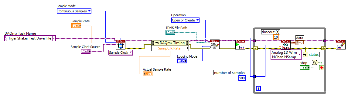
I'm trying to: record streaming channels (acceleration 21 and 1 tension) using a DAQmx task, then convert the data to a PDM file. The program files and output to the TDMS file very well. The issue I'm having is that I can't change the sampling frequency. I want to record 500samples/s and I can not get the "real sampling rate" of change of 1651.61samples / s. I am trying to use the clock to do this and I succumbed. I also tried to change the settings of "Timing" in the task without a bit of luck. Here is a screenshot of the .VI I created. I've also attached a copy of the file VI. Any help would be greatly appreciated!
Thank you
Tony
You will need to provide the model of your device. You can also look in the sheet/manual to see what the real supported sampling rates. Some devices have limited rates.
-
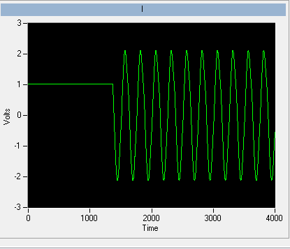
I have included my code as version 8.5 for those who have not yet upgraded to 8.6. I have also included some screenshots so that you can replicate the results I got. I hope that some signal processing guru can shed light on what I mention it further.
This VI convolves the signal of impulse response of a simulated servomotor which is essentially a damped sine the input pulse which is a step function. The signal resulting convolved should be IDENTICAL to that of the step response of the engine which is RED on the display 1. As you can see the convolution that results in table 2 shows the same structure of frequency, but its magnitude is INCORRECT. As you can see in the catches of 2 screen sizes differ by a factor of 2 & done the sampling frequency of the wave. Why the sampling frequency, impact on the scale is also very strange & disturbing.
Would appreciate any corrections & explanations so that I trust the convolution of the other wave forms of entry than just the step function.
OK, I think I have it working now. Your premise on the effect of sampling on the derivative is not the issue. Does it affect what the FREQ of levy is the basis of time of convolution. As the convolution product is not continuous but discrete the length of the array should be taken into account & the sampling frequency must be consistent with this length of array as well as 1 second corresponds to 1 second. If sampling freq is 2 kHz & the length of the array is 1000 then to get the correct time base by a factor of 2 must be taken into account. In addition, to take account of the DC, shift of the ZERO gain factor must be added to the convolved signal to get the correct size.
Thanks for making me think more deeply.
-
Synchronization of the inputs and outputs with different sampling frequencies
I'm relatively new to LabView. I have a NOR-myDAQ, and I am trying to accomplish the following:
Square wave output 10 kHz, duty cycle 50%.
Input sampling frequency of 200 kHz, synchronized with the output that I get 20 analog input samples by square wave, and I know what samples align with the high and low output of my square wave.
So far, I used a counter to create the square wave of 10 kHz, display on a digital output line. I tried to pull the document according to (http://www.ni.com/white-paper/4322/en), but I'm not sure how sample at a different rate than my clock pulse. It seems that this example is intended rather to taste one entry by analog clock pulse. There may be a way to create a faster clock (200 kHz) in the software and use that to synchronize the analog input collection as well as a slower 10 kHz output generation square wave?
I eventually have to use the analog inputs to obtain data and an analog output to write the data channel, so I need the impetus of the square wave at the exit on a digital PIN.
How could anyone do this in LabView?
Hi Eric,.
All subsystems (, AO, CTR) derive from the STC3 clocks so they don't drift, but in order to align your sample clock HAVE with pulse train that you generate on the counter, you'll want to trigger a task out of the other. I would like to start by a few examples taken from the example Finder > Input and Output material > DAQmx. You can trigger GOT off the train of impulses, start by Gen digital Pulse Train-keep -you probably already use a VI like this to generate 10 k pulse train. AI, start with an example like Acq Cont & chart voltage-Ext Clk - Dig Start.vi-you'll want to use the internal clock so just remove the control of the "Source of the clock" and it uses the internal clock. From there, simply set the "Source of the command" either be the PFI line generates the meter, or ' /
/Ctr0InternalOutput '-assuming that you are using the counter 0. You'll want to make sure that the start of the task HAVE faced the task of counter I is ready to trigger off the first impulse. They should be aligned at this point. For debugging, you can use DAQmx export Signal to export the sample clock - you can then brought the train line and the PFI pulse to make sure that they are aligned.
Hope this helps,
Andrew S
-
The data read into the buffer HAVE lack samples at the beginning
I use a box USB-6251. The program implements two channels of AI (read I and Q) on a single task and one channel on another task. The channel uses the ai\SampleClock as its clock, so that both are synchronized. C creates a digital pulse periodic rising edge (a clock basically) which is used as a trigger on an external function generator. The signal from the unit after going through some material, external signal processing is ultimately what is read by the channel of GOT it.
We know from the relevant signals, they seem to be correctly synchronized scope. IE, the analog signal to read arrived on the channel of the AI of the acquisition of data more or less instananeously when the trigger is activated. If there is a delay, it is of the order of microseconds.
However, when I read in the buffer of HAVE (repeated FiniteSamples), waveform, I always come back has a section of samples at the beginning that seem to be returned of the first actually read data-point (see attached image). This delay is of the order of milliseconds (it varies with each series).
I want to totally eliminate this delay. The signal should be a sinusoid which begins to sample 0 and is continuous through until the last sample read.
I put the code below.
Installation program:
Create analog read the task
analogReadTask = new Task ("analogReadTask");Create the virtual channel for the component I
analogReadTask.AIChannels.CreateVoltageChannel (initParams.AddrI.ChannelAddress, 'I', AITerminalConfiguration.Differential,-4, 4, AIVoltageUnits.Volts);Create the virtual channel for the Q component
analogReadTask.AIChannels.CreateVoltageChannel (initParams.AddrQ.ChannelAddress, 'Q', AITerminalConfiguration.Differential,-4, 4, AIVoltageUnits.Volts);To set the clock for the analog readings
analogReadTask.Timing.ConfigureSampleClock (string. Empty, initParams.SamplingRateHz, SampleClockActiveEdge.Rising, SampleQuantityMode.FiniteSamples, Totalechantillons);Create the mult-channel drive
analogReader = new AnalogMultiChannelReader (analogReadTask.Stream);
analogReader.SynchronizeCallbacks = false;pulseWriterTask = new Task ("pulseWriterTask");
Creating a digital output channel that provides the trigger to the U/S system
pulseWriterTask.DOChannels.CreateChannel (initParams.AddrUsTrigger.PortLineAddress, "US trigger", ChannelLineGrouping.OneChannelForEachLine ");
pulseWriterTask.Timing.ConfigureSampleClock ("/ SampleClock/AI/Dev1", initParams.SamplingRateHz, SampleClockActiveEdge.Rising, SampleQuantityMode.ContinuousSamples, samplesPerPulse);
pulseWriterTask.Stream.Buffer.OutputBufferSize = samplesPerPulse;
pulseWriterTask.Stream.WriteRegenerationMode = WriteRegenerationMode.AllowRegeneration;pulseWriter = new DigitalSingleChannelWriter (pulseWriterTask.Stream);
pulseWaveform = new DigitalWaveform (samplesPerPulse, 1, DigitalState.ForceDown);
pulseWaveform.Signals [0]. The States [0] = DigitalState.ForceUp;analogReadTask.Control (TaskAction.Verify);
pulseWriterTask.Control (TaskAction.Verify);
From reading:
analogReadTask.Start ();
Start writing the digital pulse, however it will not start
until the AI/SampleClock begins, so implicitly synchronizing the two tasks
pulseWriter.WriteWaveform (pulseWaveform, true);analogReader.BeginReadWaveform (Totalechantillons, readerCallback, analogReadTask);
Result (should be a sinusoid from end to end)
Always seems to solve these problems, shortly after their validation.
The problem has start the digital task AFTER the analog task. In the small delay between the two lines of code running, read analog had already begun, and so some of the impulses of the AI/SampleClock were missed by the task. The order of departure between the two tasks of switching solves the problem.
-
Change the value to trigger record data for 1 s sampling frequency of 50 KHz
Hello
I have a VI with NI9215 and cDAQ-9178 chassis hardware. The function of the VI came out an instruction to RS232 interface and record 1 second of data every time that the set point is changed.
The procedure is
(1) modify the policy to the flow regulator
(2) wait 2 seconds.
(3) record of 4 channels for one second to the sampling frequency of 50 KHz.
At present, the problem is for the first edition of this program, two seconds (rather than) data was saved and corn, the error message 200279.
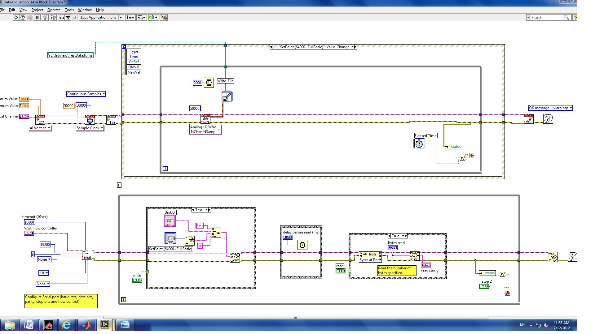
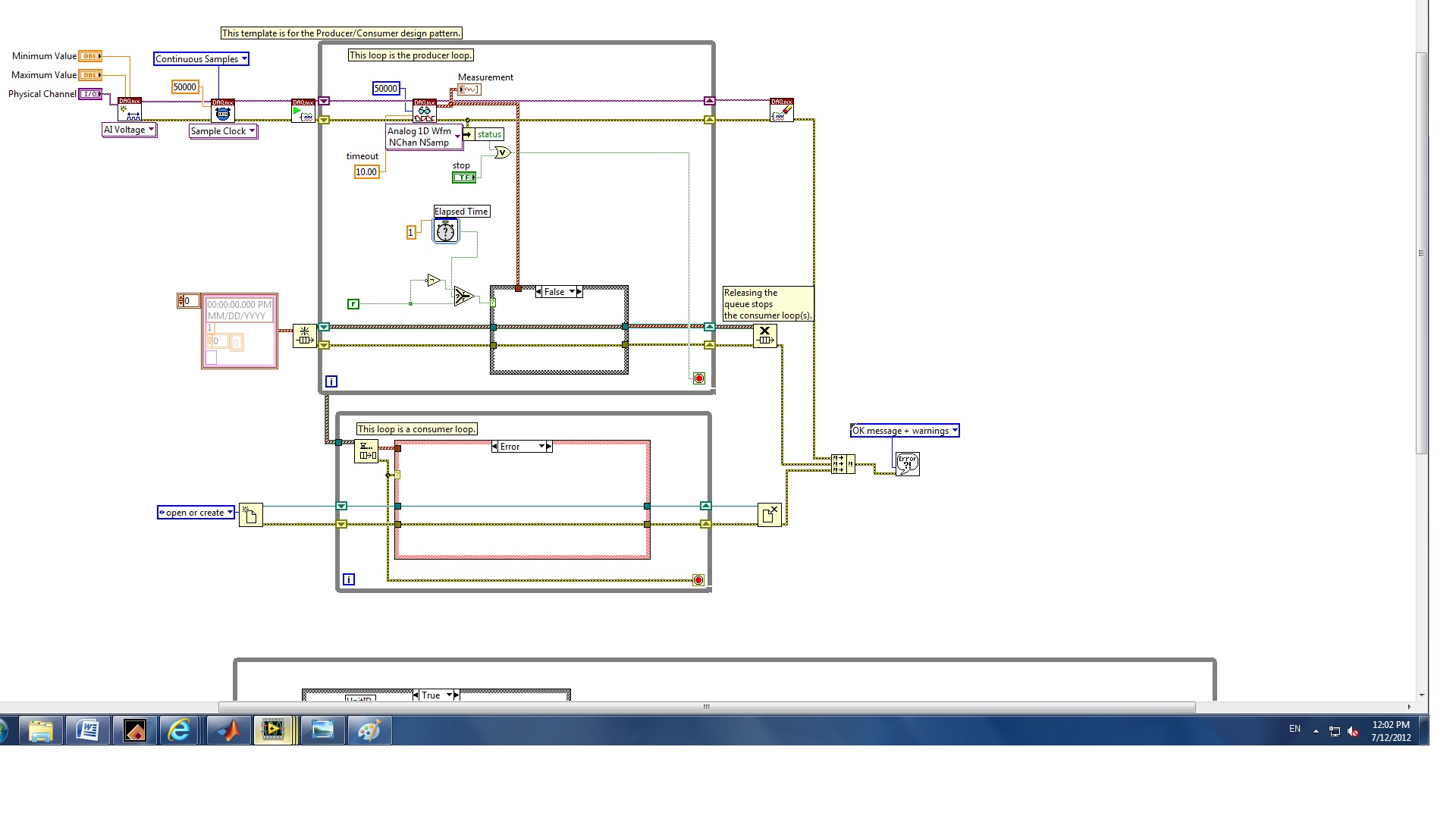
II. I revised for the second edition of the structure of the producer and the consumer who can increase the speed of the buffer.
The question is how to configure the trigger to start the backup of data and limit data save for one second whenever the set point value changes.
(1) which edition is best for my application?
(2) how to trigger the data record?
(3) how to record only a second of data?
I also checked this announcement and the elapsed time seems not to work for this case.
Any help would be greatly appreciated!
Melody
Hello
you have not used properly the nodes property.
1. replace the case structure in the first loop, with DAQmx features, with a structure of the event. Change the event fires for a worth of control of the setpoint change.
Edit: as stated in your first post, use the structure of the event, but put inside the while loop.
2. DO NOT connect error output from the stop command property node. Replace it with a local variable for the stop button.
Try these and let me know.
-
I can't stop finite samples daqmx read between the two?
Hi all
I want to read data from 10 seconds to a trigger is received. for this im using daqmx task finished sample mode and read the data on the trigger getting. It works fine but I can't stop my vi between the two when its reading of the data. I have to wait for it to complete the reading of values, and then stop the vi.
so I switched to continuous sampling mode that allowed me to stop the vi whenever I want.
I just want to know is there any means or the property using which I can stop my task over daqmx read when I want?
I guess you call DAQmx Read with extraordinary value (-1) for samples of #. It is also the default if left thread continues. In a finished sample task, it means to wait until the memory full buffer has been filled with samples before returning. Once you make that call, you cannot directly finish soon. You're stuck waiting for buffer fill or for the timeout expires (default 10 seconds).
One way to avoid getting stuck is not to ask for samples that do not exist already. You can query a DAQmx Read property, known as the "Samples available" or something like that and son of this result in a call to DAQmx Read. Such a call will return immediately whatever data are currently available. Subsequent calls will give you samples.
-Kevin P
-
How to make repeated calls to the reader in the AcqVoltageSamples_IntClkAnalogRef code sample.
I want to make repeated calls to the reader in the AcqVoltageSamples_IntClkAnalogRef code sample. A comment in the code says I can do simply by calling the reader. BeginReadMultiSample method of the callback function. I tried this without success using the same settings for the player. Is it possible for the callback function? If Yes, how should I call the reader? I'm programming in c#.
Thank you
John
Doug,
No problem. I found the class to which the timeout without much property in safely. I now have a solution to repeated calls. The two keys were the infinite time-out setting and the elimination of all the DAQmx objects in the finally section of the callback function before calling the AcquireData() method for the next cycle of reading and processing of data. The user sets blQuit to false and call AcquireData() by clicking on the Start button. Repeated calls are then made to 'automatically' until the user clicks the button exit.
Thanks for your help,
John
Private Sub AcquireData()
This code creates all the objects needed to acquire and store the data of a "sweep."
{
slaveTask = new Task(); Double sampleRate = Convert.ToDouble (this.cbxSampleRate.Text);
Double minVolts = Convert.ToDouble (this.cbxMinVolts.Text);
Double maxVolts = Convert.ToDouble (this.cbxMaxVolts.Text); int samplesPerChannel = Convert.ToInt32 (this.cbxSamplesPerChannel.Text); slaveTask.AIChannels.CreateVoltageChannel ("Dev1/ai0", "", (AITerminalConfiguration)(-1), minVolts, maxVolts, AIVoltageUnits.Volts);
Set up sync Specs
slaveTask.Timing.ConfigureSampleClock ("", sampleRate, SampleClockActiveEdge.Rising, SampleQuantityMode.FiniteSamples, samplesPerChannel);
Set up the reference trigger. US fires with a level of 1 volt and will record 2 samples of trigger before (the minimum)
slaveTask.Triggers.ReferenceTrigger.ConfigureAnalogEdgeTrigger ("APFI0", AnalogEdgeReferenceTriggerSlope.Rising, 1.0, 2);
slaveTask.Stream.Timeout = - 1;
slaveTask.WaitUntilDone ();
Check the task
slaveTask.Control (TaskAction.Verify); InitializeDataTable (slaveTask.AIChannels, ref dataTable);
acquisitionDataGrid.DataSource = dataTable;
Reader = new AnalogMultiChannelReader (slaveTask.Stream); drive. SynchronizeCallbacks = true; drive. BeginReadMultiSample (Convert.ToInt32 (cbxSamplesPerChannel.Text), New AsyncCallback (slaveCallBack), null);
}
catch (System.exception DaqException)
{
MessageBox.Show (exception. (Message);
slaveTask.Dispose ();
}
}
private void slaveCallBack (IAsyncResult ar)
{
Try
{
read data from the channel
data = reader. EndReadMultiSample (ar);
dataToDataTable (data, Ref dataTable);
plot the data here, if blKeep also write it to file
}
catch (System.exception DaqException)
{
MessageBox.Show (exception. (Message);
}
Finally
{
This. Refresh();
slaveTask.Dispose ();
If (! blQuit)
{
AcquireData();
}
}
}
Maybe you are looking for
-
How can I migrate thunderbird from ubuntu to windows 7
I'm not bad with the computer stuff, but I'm having trouble to my Thunderbird of Linux Mint profiles migration to Windows 7. I looked at several forums, but the reviews are either comprehendable or simply not what I'm looking for. Can you help me ple
-
iTunes does not transfer music to iPhone
Hi all, thanks for your help and input here. I am trying to download/rip my collection of music (albums about 550 or 650 ~ disks - CD hardware purchased) from an external drive (3 TB WD My Passport) ALAC encoded on an iPhone 6 128 GB, 256 KB AAC conv
-
My laptop does not work when I restart itonly blue screen shows and give massage this system error bad config infoWhat should I do? Moderator note: title edited/model name inserted.
-
My DAQ system includes measuring RTD temperature via a NI9219 module. The usual analog to (NI9201), analog out (NI9264), digital in, digital out (NI9401) work fine and run properly with a single software timed while loop 20 Ms per iteration. When I
-
Unable to repair using PC companion for Windows software
I have software problem experience in my Sony Ericsson SK17i... I tried to update via PC Companion, but the PC Companion say... "the device can not be updated using this computer, please try again using a computer that is running windows 7 or an earl