Reading of thermocouple
All, I am new to this, make an old system of will vary from data upgraded. I've been through basic training 1.
I have a problem.
I use one OR momo-9178 with NI9211 and NI9205. The NI9205 is a simulated flow signal removes a conditioner of frequency. I use the DAQ Assistant to acquire signals. I am currently plotting flow vs temp just to get an understanding of the XY plots. My problem is this... when I write temp and flow values to a file TDMS I noticed that my thermocouple measurements are as follows (see below). Don't know what I'm doing wrong, can anyone help, see attachment.
| 78.52764246 |
| 78.52764246 |
| 78.52764246 |
| 78.45823079 |
| 78.45823079 |
| 78.45823079 |
| 78.45823079 |
| 78.5143133 |
| 78.5143133 |
| 78.5143133 |
| 78.44951917 |
| 78.44951917 |
| 78.44951917 |
| 78.44951917 |
| 78.45512712 |
| 78.45512712 |
| 78.45512712 |
Hi rfireton,
Is the concern that there are 3-4 copies of the same data?
The reason is that the 9211 is considered a module included in the slow sample (14 s/s in this case). A feature of these modules is that they allow you to define a sampling frequency more quickly what is technically possible on the module, but just repeats the data if necessary. This feature was a necessity for these modules included in the sample slow to operate in the same task in the form of modules faster as the 9205.
Indeed, the former cDAQ chassis (9172), he was required to put all the modules of analog inputs in the same spot. 9178 chassis more recent that you use it is no longer necessary (but it is still possible). 9178 a 3 engine synchronization of input analog, so you can actually run a separate task for your 9211 at a rate of support if you want to avoid receiving duplicate data.
Best regards
Tags: NI Hardware
Similar Questions
-
Reading of Thermocouple Type K with myRIO
I have a myRIO (room only) and I need to read for an internal PID K type thermocouple measures. I am able to do this directly in the room? Or I need an adapter?
Be as specific as possible.
Thank you.
The above listed connector is the connector for the card myRIO only.
In addition, the thermocouple type k has a + and - sign. If the + needs to go to one of the analog inputs and - needs to go ALWAYS, analog ground. See page 5 of the below myRIO 1950 manual for the pinout of the connector.
-
I can't read thermocouples on the PXI-6225-series M 1 connector.
I'm reading 30 measures by thermocouple in differential mode. I use AI0 as the CCM. Attached are the connections that I use. Negative contributions all relate directly to the GND AI.
I have no problem to read the thermocouples in slot 0 (AI1 by AI 7). I have install Connector 1 direct feed by mode (switch 1 & 2 right and switch 3 upwards). In MAX, I get a normal reading, but it does not vary by heating the thermocouple. In my real program, it is as if there is nothing connected. Any ideas as to what I can hurt?
Thank you
Mark
Mark,
Thanks for posting. I think the question might be to see you about the how the SCB-68 must be configured in mode of direct crossing to be used with the connector 1 on the PXI-6225. When the switches on the block are defined for a direct crossing, the Council is not connected to the CJC. Do not have a connection to a CCM on this connector could cause this problem.
A potential solution, you can try is to connect a temperature probe to AI16 and follow the steps in this KB, using that channel instead of the CJC channel. Let me know if it helps!
Kind regards
Joe S.
-
Reading of temperatures using PXI-4351
I can't configure my PXI-4351. I can't read a measure of a thermocouple unless I run NI MAX Test Panel for the temperature at the same time as I run my Labview code. If I open the test panel and configured to read a thermocouple, my labview code will read for a thermocouple. If I close the MAX test Panel, then the labview code stops playing correctly. It gives me false readings.
Here's what I do in LV:
NI435X INITIALIZE
NI435X SET RANGE-online high limit = 0.625, limited low =-0.625 = 1 channel
NI435X CHANNEL MODE SET => Thermocouple T (8)
NI435X SET CJC-online manual (I don't have a box of accessories connected to the 4351 - thermocouple is connected directly to the pins on the channel 1 of the 4351)
NI435X SET NUMBER OF SCANS-10 ONLINE
NI435X SET POWER LINE FREQUENCY-60 ONLINE
NI435X SET LIST OF SCAN-ONLINE CHANNEL 1
NI435X ACQUISITION START/STOP-START ONLINE
NI435X CONTROL AND READ-ONLINE TIMEOUT = 1000, SIZE = 2048 SCANS
NI435X START/STOP-STOP ONLINE ACQUISITION
CLOSE NI435X
I'm running 7.1 LV and MAX 4.0.0.3010, I don't know what my version of NI435X - and I don't know where to find this info.
You can see where I could be missing something in my configuration of thermocouple?
Thanks, Corby! I appreciate the help and I run last night. The problem seems to be in the loop. I didn't have my function playback looping and for some reason any, it is necessary, even if you take only a single reading. I don't understand why - but at least it works this way.
-
NI9213 Thermocouple measurement noise AC
I use a cRio with various thermocouple C-Modules NI9213. For my application, I need thermocouples not be safe and be very close (same body) sources and AC cables. When I read the thermocouple values that are close to the AC cables, I see noise sinusoidal structure in different frequencies (according to my sampling frequency). I use high-resolution scanning engine (mode high speed gave a louder signal). I would appreciate any help on this matter. Should I ground my cRio in a particular way? My last resort will be to sample at a higher frequency and the average of the values (assuming 60 Hz noise, I want to sample at least 120 Hz).
Thank you!
Thank you very much for your answers.
I had to settle for ' high resolution ' on the NI9213s and its rejection of 60db 60 Hz with some 'best practices' noise when the wiring of the AC power lines and thermocouples. However, the noise is not completely filtered. Looking around for other data acquisition devices (no OR in particular) I found modules thermocouple with at least 120db 60 Hz noise rejection. I personally use another provider of data acquisition with a thermocouple module that filters the noise of 60 Hz as a charm. I wonder why limited filtering on the NI9213.
-
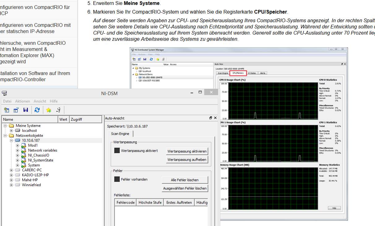
Slow down the host Communication target in real time
I start with Labview RT.
I wish that tor gave reading a thermocouple signal, then sending to host VI. It works, but to slow down.
I tried to look at CPU, memory usage, but it's my second problem. The DSM does'nt contain functions should be.
Am I missing a special configuration?
Published network shared Variables are slow, especially in a high-traffic network. I recommend that you use a network stream and set up your own communication scheme capable of handling the output rate higher.
-
How to configure a lab overlooking tubular heat exchanger to get data
Hi
 I
IIn our undergraduate engineering chemical labboratory we want to configure our DAq with lab VIEW tubular heat exchanger to get information on the temperature (flow cold fluid warms up), (the steam pressure on the side of the hull of the heat exchanger) and flow (water warms up).
Can anyone suggest thermocouples, pressure transducers, and flow meters to stay between the heat exchanger and the acquisition of data?
P.S. the heat exchanger is already equipped with a pressure gauge, thermometers and a rotameter, but we do not know how to connect these devices to data acquisition
Looks like you have enough information to choose appropriate sensors, you just need to do the research. I start looking into Omega catalogue, or give them a call - they are generally useful. I can't take the time to spec parts for you - it would be a lot of time on another project. Most pressure sensors put a signal 4-20mA or 0 - 5V, that is which you can read through an analog input on a data acquisition; measure a 4-20mA signal requires a resistance to convert voltage. Most NI DAQ boards can read a thermocouple on an analog input, but make sure that your hardware is supported reading thermocouples. For an accurate reading, use a device that has the compensation of cold welding integrated - for example, the block connection SCB-68 - and for more accurate measurements, get a Board specifically designed to measure the temperature.
For measurement of the flow, a standard, simple solution is an orifice plate. You put a transducer for differential pressure across it, seek the appropriate equations and use them to calculate the flow rate given the density of the fluid (which you will be able to calculate from the pressure and the temperature, since the steam tables are widely available). Other differential pressure devices are available as well - at a previous job, we used a double cone of McCrometer. If you call them, they spec for you - but get an approximate cost first to make sure it's in your budget.
-
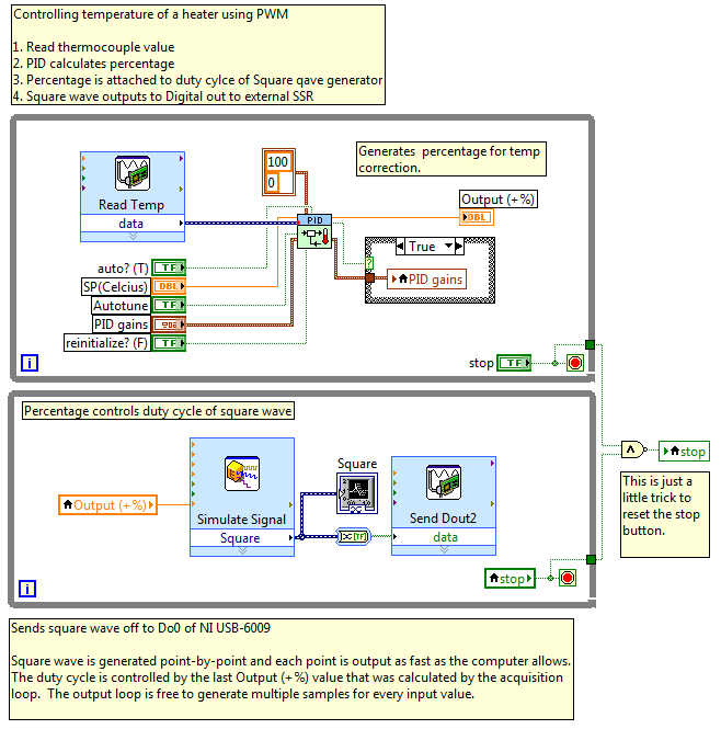
Hi all, I do what would appear to be a straight forward VI. I'm controlling a small radiator that is monitored by a thermocouple. I read the thermocouple using the DAQ assistant. I use the PID of the Toolbox example. Then I generate a square in the cycle of use depending on the percentage of the PID gives. Strange thing is that all the parties separately work fine. But when I put them together I get no square signal, I can only see the transistions modified for long periods of time. I have pin pointed the problem when I use the DAQ assistant to read the temperature. If I remove it and insert a control I see the square wave. The system seems to favour assistant DAQ which reads the temperature, then generates impulses 'if she has time. I don't know there is something I have to do with the sync'ing of the two assistants DAQ. Any help would be great! Thank you
I second RavensFan reply, but if you were satisfied with the way the USB-6008 housing has been able to generate an isolation square wave then try something like this:
Two loops using dissociates the acquisition of synchronization of generation time allows many points of your square for each reading of the temperature of output.
Hope this helps,
Simon
-
How to make a USB-TC01 temperature data a global variable?
Hi all! I have a simple question (probably). I bought the box USB-TC01 and with the software came a VI called LabVIEWTempLogger. This VI reads a thermocouple voltage and internal conversions using DAQmx and a CYC edge to give a reading of simple temperature. My problem is that I want to use this temperature in an another VI, then I want to make a global variable of temperature of LabVIEWTempLogger. How to set a global variable such as temperature of LabVIEWTempLogger? Thank you!
You must get out of the recorder temperature VI the DAQ Assistant. Put it in a Subvi if you wish.
Your main VI has some problems. The first fact a comparison is equal to the current temperature. Never make an equal comparison on a floating point number. Use in the range and force.
The local 'Set Temp deg C' should be replaced by a wire from the Terminal. All local variables should be replaced by a wire. You can easily have the cable terminals from outside the main loop.
Can't the difference in code in the States True and False when you read voltage.
Don't use VISA bytes to the Serial Port. It's just bad style. You programmed it for a terminal character LF to get rid of fixed forward and set the number of bytes to read at a high number. Playback will wait until the stop character is detected and then automatically end.
Finally, you have already created a world so I do not understand your questions about it.
-
Error-200478 - specified operation cannot be performed when there is no channels in the task
I write a task in NiDaqmx read 8 thermocouples 2 9222 or 4 thermocouples of a NI 9223 modules. Under Source of CCM I entered the channel and specified a type K thermocouple connected to a NI 9219. All modules are located in the same chassis of cDAQ9178.
I get the above error.
I add the CJC channel and he complains that I have double readings of the same channel in one of the tasks.
The environment where it will be installed will vary widely affecting thus the constant CCM is not a viable option.
Any help would be appreciated.
Simple reason - we already possess the 9222 s of NOR and the NI 9223. I'll check the price NI9213 and see if the Group has the budget.
I watched your program and compared it with mine. Tried to channel the CJC as Temperature_12 but all local channels are grayed out. BUT I moved Temperature_12 the command to the top you and Voila! He is available for selection. I put all 9222 s and 9223 channels at points to Temperature_12, and it saved without error.
So I would say put the CJC channel as the first channel to read fixes the problem - it makes sense that the following channels need a reading to serve their CCM. Where this logic breaks down is if you consider that the 9222 and 9223 channels are simultaneous channels, but that's a topic for another post!
For now, I thank very you much for your help.
Best regards
Dean
-
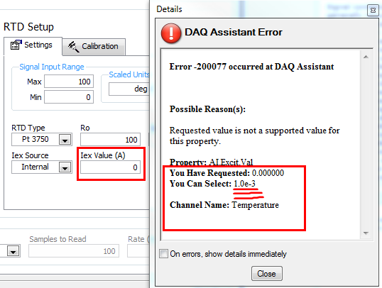
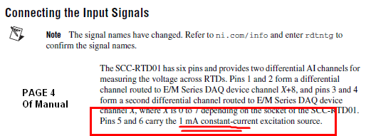
Turning off the current excitement of SCC-RTD01
I have an extensometer which has 4 wires instead of two. The reason why I have four sons is because to each pad, I a chromel and alumel wire to create a thermocouple. This way I can measure the temperature right at the gauge (two TC by gage).
I need to measure the resistance of the gauge that I change the temperature. I have a module SCC-RTD01 can I use to measure the strength of gage (I did actually and it worked). But since this module puts a 1mA current excitement, my reading of thermocouple is false (because the current passes through at least one of the sons, creating a tension which is not pure the thermocouple voltage).
Is there a way I can turn the excitation current LabVIEW? Alternatively, does anyone have another suggestion? Thank you.
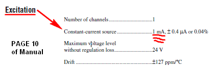
Hi JG001,
Thank you very much for clarifying the issue, I now understand your request. The fact of the matter is really that the excitement is broken out to its own terminals dedicated; It cannot be turned off, and in the Manual of the SCC-RTD01is. You can also check this by entering a 0 my in your task to the excitement and you will find that this is not a supported value, only 1mA is a supported value and it will throw an error, as shown below. I've also included a few screenshots from the manual that describe it. The excitement can be disabled, 0mA if a value supported for the current level of excitement. I hope that this clears up any confusion. A possible solution would be to use a relay to activate this, perhaps the SCC-RLY01.
-
Hi all
I'm working on an application of temperature. I take the thermocouple reading from a device of FP-TC-120.
I want that reading of thermocouple to stay in the range of 1 degree accuracy, for example for 10 minutes. To do this, I wrote the attached VI. (Target value and time required temperature are entered in VI.) The problem is that I want that time to be reset to zero when the value of the temperature falls out of scope. In the application, I wrote that it resets the little matter that the reading of thermocouple. The problem has something to do with the structure of the case? (I tried to use while loop, but I had trouble getting the thermocouple inside the loop of reading)
Thank you
Deniz
The way you have it, the timer resets whenever the front panel boolean is true. You have absolutely no connection with the thermocouple reading being within the range or not. A simple solution is shown below.

-
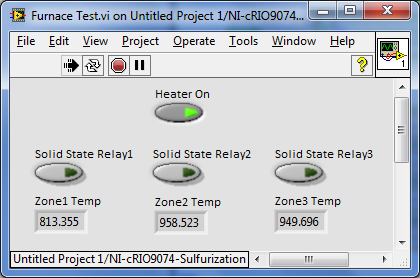
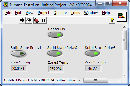
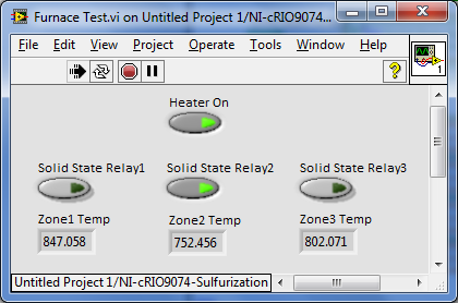
Strange thermocouple at the time reads high
I have a problem my thermocouples to high playing time. I have a cRIO 9074 with a connected to 3 K type thermocouples 9211 thermocouple module. Thermocouples monitoring 3 heat zones from a giant furnace, in which areas can be activated and deactivated with the help of a relay. When activated, the thermocouples read the temperature normally up to 800 ° C. However, when it goes beyond 800 degrees, it can seem to read normally, but when you place radiator different relay on or off, the thermocouple reading significantly changes a few times. This does not happen below 800 C see attached photos and assume that the first photo is the right base temperature:
When I joined the first box to an external drive thermocouple with its own digital screen, I don't see this radical change when switching of the relay on and outside. It has remained relatively constant.
Why I see such a big change with the 9211 module? I'm not process the signal somehow, just a direct reading, and the module itself is configured to play the K type thermocouples. The heater contactor and thermocouples are relatively far.
Any help is appreciated.
Linus
Hi Craig,.
Yes, I could solve this problem. a LabVIEW engineer suggested this solution and it worked. See Section 3 (Nonreferenced) floating measurement of Sources at this link:
http://www.NI.com/white-paper/3344/en/#toc3
The source of the problem was instrumentation amplifier input bias currents, causing the voltage level of the floating source to be moved out of reach. I need to add polarization resistors to provide a path of DC since the instrumentation amplifier inputs to the instrumentation amplifier ground and anchor this voltage level at a few references. I followed resistors in FIgure 10 and added two 100 kOhm for each of my thermocouples. Since then, I have much more fluctuating readings.Hope this helps,
Linus
-
incorrect thermocouple reading
I have an NI PXI-1033 with an NI TB-2709 block and I'm under Labview 9. I'm just trying to read the temperature with a thermocouple to any of the eight channels. Unfortunately, when I look at the reading of the measure and menu task Automation Explorer value fluctuates all about the difference from peak to Valley about 50 degrees C. I tested the thermocouple on a multimeter and it gives a good reading. What's wrong. Help, please.
Once I updated the chassis ground to the shield of the input cable that the noise went away.
-
Reading of fluctuation thermocouple k type
I'm new to Labview please anyone can help would be appreciated.
I'm trying to read the temperature using thermocouple type K with a NI 9213 module in Labview.
I used two individual channels. One is the ambient air temperature.
The second is one is inside the PVC piping Assembly read the temperature of the air flow which also has moisture.
Ambient air temperature reading is working perfectly fine.
Reading the inside of PVC piping is fluctuating. The temperature varies randomly between 4-7 degrees Celsius.
My question is what causes this fluctuation of reading. Is - this air flow inside the tube. Vibration? Moisture? CYC?
Please help someone?
Thank you very much in advance
Danh

Maybe you are looking for
-
Payment options credit card withdrawal
I can't select 'none' when I change my payment apple ID information. I do not have an unpaid balance (in fact I have a gift card on my account with a credit balance); I am my family sharing Organizer; I have no automatic subscription, and still I ca
-
We have an old Ariba software and versions of browsers make it impossible to complete the process.I was wondering if I can download the old version of Firefox, one before 3.6.24.
-
ZBook 14 wireless problem solved!
For a few months now, my ZBook 14 (still under warranty) drivers wireless (Intel Wireless - N 7260 BN) were not loading at startup about 50% of the time. Pilots would almost always successfully load if I restarted, but it was aggravating circumstanc
-
Pavilion office 550-154na: Windows 10 & Lock screen customization
Hello I have a brand new out of the box PC 64-bit HP Pavilion Windows Desktop 10. I learn the tricks of the trade for Windows 10 and, above all, everything goes smoothly.However, I am struck a problem when customizing the Windows lock screen where Co
-
fatal error FN4000 stopped. CNU9192TYJ. Help, please.