Recovery of the DAQ Assistant data acquired
Hello
I'm currently dealing with a continuous data using NOR cDAQ-9174 proposed acquisition and recording of analog input signals of a built-in three-measuring probe.
I built a simple vi using DAQ Assistant to acquire data and write to an output .txt - rather than .tdms using Signal Express.
On a day 10 cycle of data acquisition computer was mistakenly turned off - leaving the empty output .txt file. LabView recovered the VI cut and I wonder if there is a way I can access the data that has been saved by the DAQ Assistant which can be saved in temporary files etc..
I have no idea where that might be, since you cannot delve deeper down into the 'levels' of DAQ assistant as you would a sub - vi.
Just as a note aside to apologize my stupidity - I realize that all the data at the end of the writing task is stupid and completely avoidable... but I worked for a date limit.
Thanks in advance for any help you can provide.
Dan
The most likely answer is not, unfortunately. It looks like you were a table of data at every point of the construction and then measure he writes at the end. In this case, unless you have explicitly recorded data in a temporary file, it is located right in volatile memory, waiting for you to do something with it.
I realize that this isn't what you want to hear, as it comes to the time of submission of draft / year...
If you post your VI (preferably version LV2012 or below), I can have a look to see if there is anything obvious.
Tags: NI Software
Similar Questions
-
Calibration of thermocouples in the DAQ Assistant, using data from spreadsheet?
Hi all
For my first application LabVIEW, I'm looking to automate the calibration of thermocouples by measuring their response at different temperatures in a dry well Sizer. I get temperatures of thermocouples six by SCXI 1303/1102/1600 and have six channels put in place in one of my subVIs in the DAQ assistant.
I compare these values to temperature calibrator that I am acquiring by VISA series in an other Subvi. All these values are written in a .csv file.
Can I import these data into the DAQ Assistant to use for calibration? Is there a simpler way to associate with the channel calibration data? Currently, I could manually copy - paste the cells on the worksheet in the calibration sheet, but that seems just silly.
If there is everything that I could provide to help solve the problem, let me know!
Thank you!
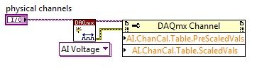
Hi Zoysiamo,
It is possible to automate the calibration screws DAQmx at a lower level, in particular the DAQmx channel property node. Using you can specify advance nationwide and the values on the scale for your channel. I recommend you take a look at this example of the community. The property node configuration will be similar to, as illustrated below:
-
Calendar and the problems of data collection with the DAQ Assistant
Hello NOR Developer area,
I am a Novice of LabVIEW and have seen how helpful you all can be, and if I come to ask for your help.
I'm having some trouble with a VI I built that specifies an input voltage, a SCB - 100 connected to a PCI-6031E and converts this tension in a temperature displayed on a waveform table. The goal is to give a constant reading of the temperature and display it in a chart for as long that the VI is running (and to reset the chart the next time the tracks of VI).
The problems I've encountered currently are:
-After a few minutes of the VI running, I get an error message 200279: tried to read samples that are no longer available. The requested sample was already available, but has since been replaced. (to the DAQ Assistant express VI).
-I don't know how to change my chart so that the minimum value X is both during which the VI was launched and have the maximum X value increases with each iteration of the loop. Currently, I have the VI get the time system and contributing to the property node X scale. This worked for the graph of the voltage, but not for the temperature chart
I appreciate those of you who took the time to read my post.
Thank you all for your help.
Sincerely,
Ethan A. Klein
SB candidate in Chemistry & Physics
Massachusetts Institute of Technology
Class of 2015
PS I enclose my VI to give you a better understanding of my current situation.
E A Klein wrote:
Thanks for writing.
What property node is talking?
I do not understand that many different data types. How can I go on the treatment of all the data?(Did you mean I should wire 'blue' data for mathematical functions rather than using the node property tension?)
Sincerely,
In fact, one of the nodes property. I mean specifically the tension property node. But in reviewing, I noticed the other nodes in property for the chart. Just set auto-scaling to the X scale and that should take care of two of the nodes property (right click on the graph, X scale-> AutoScale X Scale). I also recommend placing your mathematical functions in a Subvi to make things easier to read. Attached, that's what I think you're after.
I hope that these small tweaks will speed things up enough to avoid your error. If this isn't the case, then we should begin to look at the design of producer/consumer model or take readings at the same time. It might also be worth looking away the DAQ Assistant and DAQmx real screws. But one step at a time.
-
Units of the number of samples and rates for the DAQ Assistant units
Hello
I use the DAQ assistant for analog voltage of an input OR data acquisition card. What is the difference between the rate and the number of samples in the DAQ assistant and what are the units of the two?
Thank you.
The number of samples is how many discrete to measures. Rate (per second) is how fast to acquire the specified number of samples.
If number of samples is 100 and the rate is 1000 samples per second, then the acquisition would take 0.1 second (100 / 1000).
-AK2DM
-
201003-error occurred in the DAQ Assistant
Hello. I use "cDAQ-9178" and "NI 9215" and "NEITHER 9402" are added on. "
However, when I run Labview code, "Error-201003" occurs.
{
Device not available. Possible causes:
Device is no longer present in the system / device is not powered.
Device is turned on, but was temporarily without electricity / device is damaged
}
(Error appears as the 1st and 2nd figures below).
(Plans of logic is the figure below).
Thank you.
I could be something with the pilot
Check this box:
Error 201003 to the MAX test panel or all by running the DAQ Assistant
http://digital.NI.com/public.nsf/allkb/5413F392D88326148625746B006745C5
In this forum, they speak the same error:
Spontaneous error code 201003 for acquisition of data PCI configuration
http://forums.NI.com/T5/SignalExpress/spontaneous-error-code-201003-for-PCI-DAQ-Setup/TD-p/830707
-
Hi all
This should be a pretty simple question, but I can't seem to find the answer online and currently do not have the functionality to test this:
I'm using LabVIEW 8.5 and have a VI that imports data from sensor through the DAQ Assistant. In the configuration tab, there is a range of signal input. What happens if my sensor exceeds this range? I get a warning? The default value is the maximum (or minimum)? I was interested in writing a code to display an error that I approach the limits of this range, but did not know if I also need to include code to display an error if the scope is exceeded as well.
Thanks for the help,
Tristan
Hello, Tristan,.
The behavior depends on the selected range and the device you are using.
If you are using a device with a single input range is valid, we will use this range, even if you set a smaller minimum and maximum in the DAQ Assistant. So, if your device only supports ±10V and you set the range to ±8V, you will still continue to get valid data after your top sensor 8V until what you approach 10V. When you reach the limit of the extent of your device, the output will be 'rail', and simply return the maximum value until the signal is less than the maximum value again.
Note: A device that is nominally ±10V usually has a go-around (such as ±10.2V) which are usually specced in the manual.
However, if you use a device with several ranges of entry then things become more complex.
NOR-DAQmx player will choose the smallest range that entirely covers the interval you choose. For example, suppose that your device supports the following input range: ±0.2V, ±1, ±5V, ±10V and you choose 0V - 3V as the range in the DAQ assistant. The NOR-DAQmx driver will focus on the input range and the list of the entry lines that your hardware supports and choose the smallest encompassing the entire range that you set. This would be the ±5V, because this is the only beach that contains up to 3V. Thus, all between ±5V input signal is returned and none outside this range will be 'rail' to the maximum or minimum value.
We do this because using small beaches make more efficient use of the resolution of the ADC. So, we try to use the most effective range based on what you ask without picking up a range that will make you miss data.
Let me know if I can clarify it more.
-
Precise triggering voltage input and output generation in the DAQ Assistant
Hello
I wonder if anyone has come across a simular problem with the synchronization of input and output voltage. I use a box 11 LabView and NI USB-6259. I have been using the DAQ Assistant to configure the input and output channel. In particular, my task is to generate a single rectangular "pulse" as the output voltage to drive a coil and once the pulse went to get a signal from a sensor of magnetic field and get a power spectrum. This means that the order and the time during which the DAQ Assistant is used is extremely important. For example, the output voltage channel must be opened first for 2 seconds. Subsequently, the channel of input voltage must be open for 1 second, in which the sensor signal is obtained and post-processed. Only after these tasks are performed in this order he can can be repeated in a loop until the experiment is over. I don't know how to trigger data acquisition assistants (one for entry) and the other for the voltage output correctly. Y at - it a trick?
See you soon
Michael
Hi Dave,.
Thank you that I wired the error strings but the timing issue was unrelated to it. In the DAQ assistant, I simply had to choose the continuous aquistion of the 'samples' methods 'N-switch' for input and output voltage and all works fine now.
Thanks again
Michael
-
New Daq with the Daq Assistant in the filtering code
Hei,
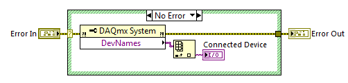
I have a NI USB-6225 DaqMx I used a couple of years. When I started with LabVIEW, I found the Daq Assistant to the best way to measure the voltage with my Daq etc. My company has purchased another DaqMx NI USB-6225 and now I have a big problem: the Daq Assistant in my old Vi does not work with the new data acquisition. I understand why there is this problem, but I do not know how to solve. I found this code on the forum who finds that Daq is connected:
The problem is that Daq Assistant do not have an entry for it, and it gives me an error if I try to run the code with a different device than the original, I used when I created the code.
Is there a way to solve this, so I don't have to convert all the Assistants Daq normal code?
Hello again,
two options:
(1) as the old software is related to 'Dev1' you must rename your new device to this alias and skip/rename the old device (and lack).
(2) rewrite your old software does not become is not dependent on the name of the alias for the data acquisition card...
It's your choice!
-
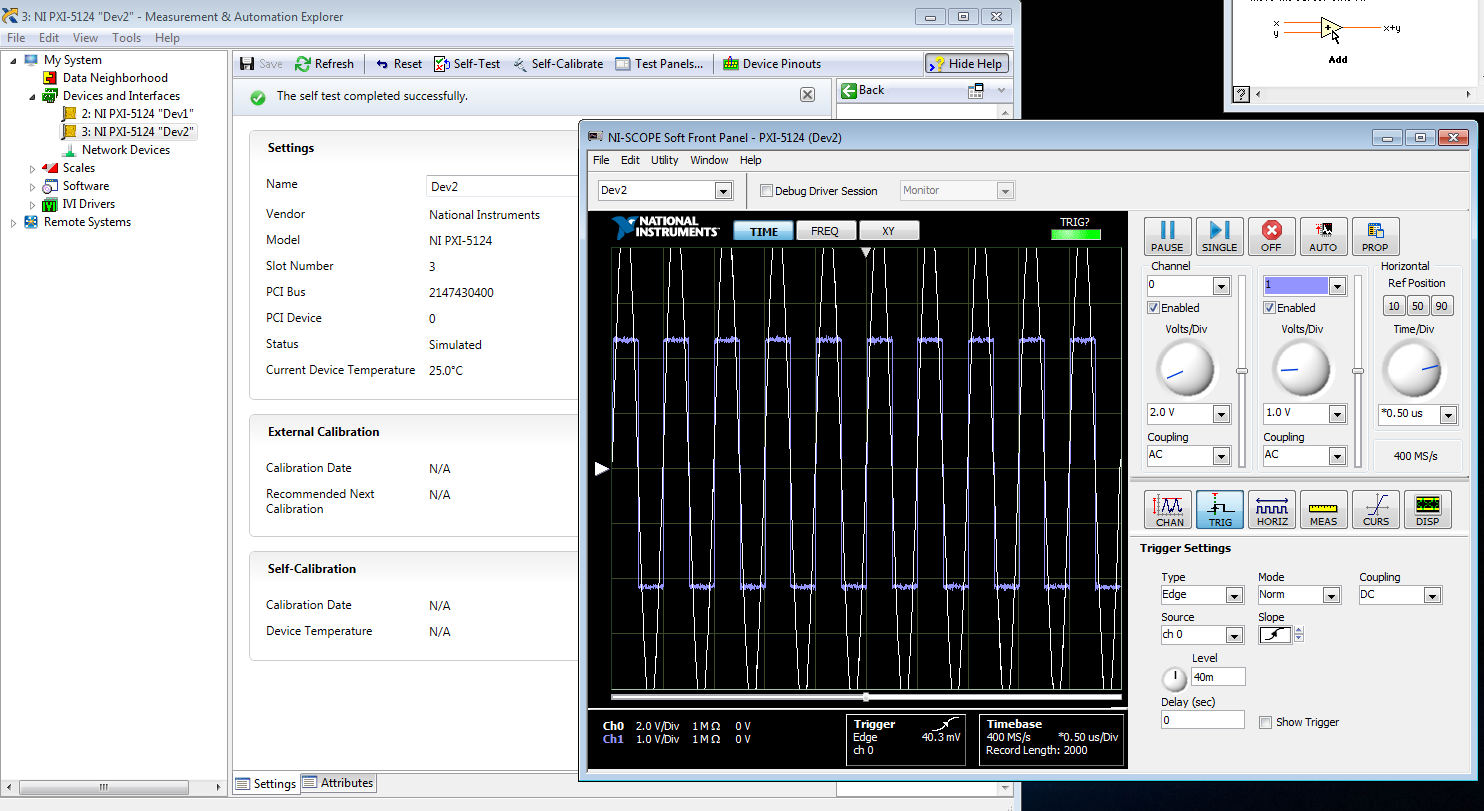
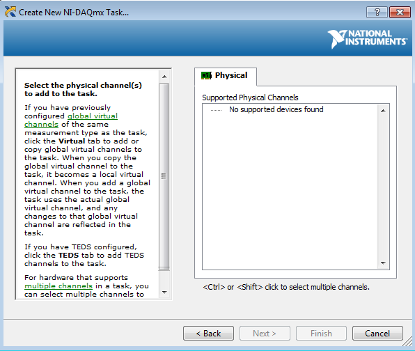
I am trying to create a development machine, where we can test the new code without using our physical hardware. I followed this guide to set up a system of simulation. I get to step 3.2 b, but the device does not appear in the DAQ assistant. MAX, the device self test and gites calibrated successfully, and when I open the test panels, I see some sort of signal. I guess that's a default entry simulated since I didn't that device to look for anything? Note that two devices, I am creating the show upward into the devices section and Interfaces, but that, even after running auto calibrate, automatic Calibration date is not yet specified.
When I try to test the device and create a voltage according to the guide, I can't see a device in the creator of data acquisition task.
Steps 1 and 2 of this guide are of course met. Step 3 is not, but this is not surprising because a simulated device is in device in any case manager. Also, I'm not under RT, so step 4 is satisfied.
Someone at - it ideas?
That would be because the PXI-5124 is a digitizer not an analog input device. You must use the NI SCOPE not NOR DAQmx driver
-
Why don't the graph and the table of the DAQ Assistant, when it is run more than once
I have a vi that collects data and the poster. When I press the run button, it collects data as expected. But, if I changed the samples or the rate and press the run button, it collects data on the previous values of the sample and rate. I have the release of the vi and run it again to perceive in the correct values of the sample and rate.
I plugged it without the DAQ Assistant and everything works as expected. Thanks for your help. Now, just curious as to why DAQ Assistant does not work well.
Thanks again!
-
Using the DAQ assistant voltage vs time graph
I'm relatively new to all Labview and terms and everything which affects programming. I've read tutorials and everything trying to understand things. One thing that I have a problem is the DAQ assistant. Now, if I wanted to place the DAQ assistant on the block diagram of labview and I have everything set up so that the voltage will travel in the DAQ hardware, how would I set up my block diagram so that I can get a graph of voltage vs time in which data begin recording until the voltage reaches a certain tension I was inputing and change such as 30 or 40 volts. The data will also stop recording when the voltage reaches the same number. I also want to be able to multiply the number of voltage coming out a number that I can change myself before it is graphed over time. Example, I mean the voltage to start recording when he reached 40 volts. Now when the voltage comes out of allows it to DAQ assistant say he is somewhere read 10 volts and the number I want to multiply by 5. So, I want to be able to multiply the voltage by 5 and then since it will be 50, it would begin graphing this number over time.
You would need to have a Boolean value which controls whether the (amplified) voltage is greater than N.
If so, he would send this value to a graph, if not, the tension would not get graphically.
Here is an example: (do not try to copy this code exactly, because it does not use a signal, but rather a whole number that is being created)

-
Hello, this is my first post here,
I've been wondering about this:
When you configure a new daq with the daq Assistant, is the resolution applied to the voltage / number of entries you define, or is it a fixed value per volt by channel.
For example:
I have a 6015 usb data acquisition, it has 16 inputs analog, 16-bit resolution 250 kech. / s 09:50 volts.
so is this as (2 ^ 16) / (16 * (-10-10)) = my resolution through volt?
or that this has nothing to do with the amount of channels,
If I want to measure more than 0 to 5 volts, my 16-bit apply from 0 to 5, or even more scale of data acquisition (which is 09:50 volts)
Thank you
Marco
You will get full-resolution 16 bits on each channel regardless of the number of channels is configured. Renault most are multi-plexed if your specification of sampling RATE in usually a global significance that you can only scan channels with a sampling frequency = MAX RATE / number of CHANNELS. Also, most NI Renault have a Programmable Gain amplifier on the front-end server, so if you specify a range of voltage smaller in your task configuration the amplifier will automatically increase the gain to use most of the possible BIT ADC. You see care device and for more details...
-
There is no entries or exits on the DAQ assistant to connect to
Hello world
I'm new to labview and have encountered difficulties with the DAQ assistant. I'm under v8.0, v8.7.1 OR-DAQmx labview and have an acquisition data PCI-6224 installed. It seems that every time I have let down the DAQ assistant (assistant of the instrument and data acquisition simulated has the same question) on the block diagram and configure it, it don't y no input or output that I can wire a control or an indiactor to. Y at - there a step I'm missing somewhere?
Thanks in advance!
Try to repair the DAQmx driver through control panels and see if that solved the problem.
How to uninstall or repair OR software?
http://digital.NI.com/public.nsf/allkb/AC6ED75D3D93375686256E8E00245F0D
-
Simulate signals wired to the DAQ assistant for USB-6009 device
Hello
I'm trying to send a signal to the DAQ Assistant Express VI. I watched the movie "Generating a Signal" on the Web site of NOR (www.ni.com/academic/students/learnlabview/generate.htm) and I have my Signal simulate connected directly on the DAQ Assistant, as shown in this film. In my case, the DAQ Assistant sends the signal to a device USB-6009.
However, I received this message:
Error-200077 occurred to the DAQ Assistant
Possible reasons:Requested value is not supported for this property value. The value of the property may be invalid because it is in conflict with another property.
Property: SampTimingType
asked the value: Sample clock
You select: On-demandIf I select 'On Demand' in my DAQ assistant and run the vi everything works beautifully. However, I need my DAQ assistant to be configured to generate a waveform AC continuous, not output a single alternating current rippling.
What happens here? I did not have this problem before on other devices of NOR. I am using LABView 2010.
Please answer.
Thank you.
-
Multiple entries to the DAQ Assistant
Hello

I'm doing my DAQ Assistant, in several (formed of an array) Boolean inputs where there is 1 digital output. (see attached software folder)
Physically, I want a valve to open and close at a certain pace, where the user can install/control this pattern until the program starts.
I think that the best way to do it is to have multiple Boolean values that the user can press or unpress.
Before that, I started, I tried with only Boolean 1 where it worked perfectly.
As seen on the attachment (error), it is possible to an easy problem to solve, but I just can't figure it out, I'm stuck at my already made solution.
I use USB6008.
I hope that there is a gentle soul who can help out me.
Best regards
Kenneth G. Vejen
Hi Kenneth.
When the output to the generation mode is set to "sample 1", which means that whenever you call the DAQ Assistant will generate 1 sample. In order to generate 5 samples, you must therefore call 5 times.
I have attached a modified version of your VI, which shows a way to archive it. However, be aware that the samples will be generated fast and not at 100 ms note your loop runs. It depends on your application, if it is as you want samples to be issued.
Maybe you are looking for
-
[iPhone 7 more] Apps not downloading
Hi all So I restored my iPhone from a backup, but found that none of my apps were download, they were just stuck on "waiting" for 2 hours. I then set the phone like new in hopes of then comes to be able to download new applications. However has no to
-
Untrusted connection is missing section "I understand the risks".
Run Firefox 33.1.1 on Windows 7, try to access https://code.google.com. I get the page "this connection is untrusted", (specifically sec_error_unknown_issuer), but there is no section "I understand the risks" to allow me to add an exception. Other po
-
How to remove the password of BIOS on Satellite L40?
Hello I would like to know how to get rid of a bios password. It happens that the machine starts and does not allow me to enter bios or as far as the post screen.I have a PSL 48F.
-
How to access the advanced settings of BIOS on Satellite P100?
Hello.I have Toshiba Satellite P100-324.How can I access BIOS adv, such as USB Legacy Support settings?For example, Free BSD so requires, also my older hardware.Help, please! :)
-
I'm doing a single image from a folder of multiple images. Images are jpgs, which is also I wish that the final image. The final product should be a grid square with all the images edge to edge. Currently, I have acquired regarding their reorganizati