Redeclenchables problem DAQmx
Hello people,
I'm fairly new to LabView and would be happy to use some help and advice from more experienced people. Basically I'm doing a vi that gives a square pulse of given width each time the trigger is activated. The pulse width is the setting that I can change one trig to another or keep the same whereby whenever I run the trig as the pulse of the same width is produced.
Running through the examples that I found on this forum and support OR that I managed to do a vi that almost work.
http://forums.NI.com/NI/board/message?board.ID=170&thread.ID=267677
http://digital.NI.com/public.nsf/allkb/82C9F3C15F62974E86256EBA0058CAF5?OpenDocument
As you can see on the photo in order to change the pulse width I use 'Pulse Width (ms)"local variable associated with while loop that checks if"Pulse Width (ms)"has been changed and if so, after the trig, gives the impulse to the new width. This part of the programme of work.
He who does not work is when no change in pulse width has been filed. When I start a vi I can trig a pulse once but can't re-trig, unless I have change the pulse width (can I change to a new value, and then replace the old value and it will work, but it is not convenient).
For some reason my task is not retiggerable when is the wrong case (it is i.e. no change in "Pulse width (ms)"), even if the Start.Retriggerable parameter in the property node is set to true. Again, this works well in the real deal, when there is change of variable pulse width (ms).
Could please point to what mistake I make and what to do to make the fake retriggereable case as well.
Thanks in advance!
(PS: I use USB-6211 card.)
Thank you for your reply Owen.
I found the mistake that I did. The variable "Pulse separation" that feeds on "Pulsed CO" DAQmx event has been set to 50 seconds (I not a not divide by 1000 to make in miliseconds units). This means that even if I retrig for a pulse again immediately after the first, the new show would ' t Pulse before 50 seconds (and I've never waited as long as my pulse are more in the range of milliseconds).
Now looks like a stupid mistake (and probably is) but I thought that this variable was significant only in the case of the event of multiple pulses (such as the implementation of "Timing: implicit" DAQmx event). In fact, even if the "number of pulses" is set to 1 (which was my case), it seems that although the envelopes works we see a pulse before "Pulse separation" elapsed time and awaits me as if work Eid ' t envelopes...
In any case, thank you for your time Owen!
See you soon!
Tags: NI Software
Similar Questions
-
Hello
I use DAQmx Write (Bool digital 1Line 1 point) to send a Boolean sample to a digital output channel. I want to be able to tell if the signal is strong or weak, so I use DAQmx Read (Bool digital 1Line 1 point) to take up the task as input and then plug a light at the end of data. The problem is the light lights up when I pass False to the VI DAQmx writing and does not shine when I pass the value true to the writing DAQmx VI. Shouldn't the DAQMx Read VI be output Boolean even as input to the VI DAQmx writing? In others, should I not get a true reading VI DAQmx if I pass a real in the DAQmx writing VI and even for a case of false?
See code attached for simplified example of what I'm trying to do.
Thank you
Jason
Which would make sense if the channel is configured as an open collector output. This would mean that the line is retrieved when you write a REAL low and left floating when you write a FAKE.
-
Who what to compile the Mac DAQmx Base examples?
I get a lot of errors. See annex.
Hi Ben_01880,
It is a known issue with Mac OSX and DAQmx Base. It happens when OS x starts in the 64-bit kernel instead of the 32-bit kernel which requires DAQmx Base. Here is a workaround in the DAQmx Base Help file:
"Xcode 3.2 or later by default to 64-bit (x86_64) architecture at the call of the GCC on 32-bit OSX 10.6 If the 64-bit system hardware." This will result in errors during compilation. To resolve these errors, force gcc to use the 32-bit (i386) architecture in OSX for 32-bit installations by adding "-arch i386' for flags in your Makefile:"
"Flags =-O2-arch i386 '.
There is also an article on Mac support site that shows how to force OS x to start the 32-bit kernel on a basis of by-boot:
http://support.Apple.com/kb/ht3773
Finally, there is a forum OR discussion about this problem and how people were able to solve it. I link you to it because it's a good resource:
I hope this helps, let us know if you still have problems!
-
Timestamp problem DAQmx waveform
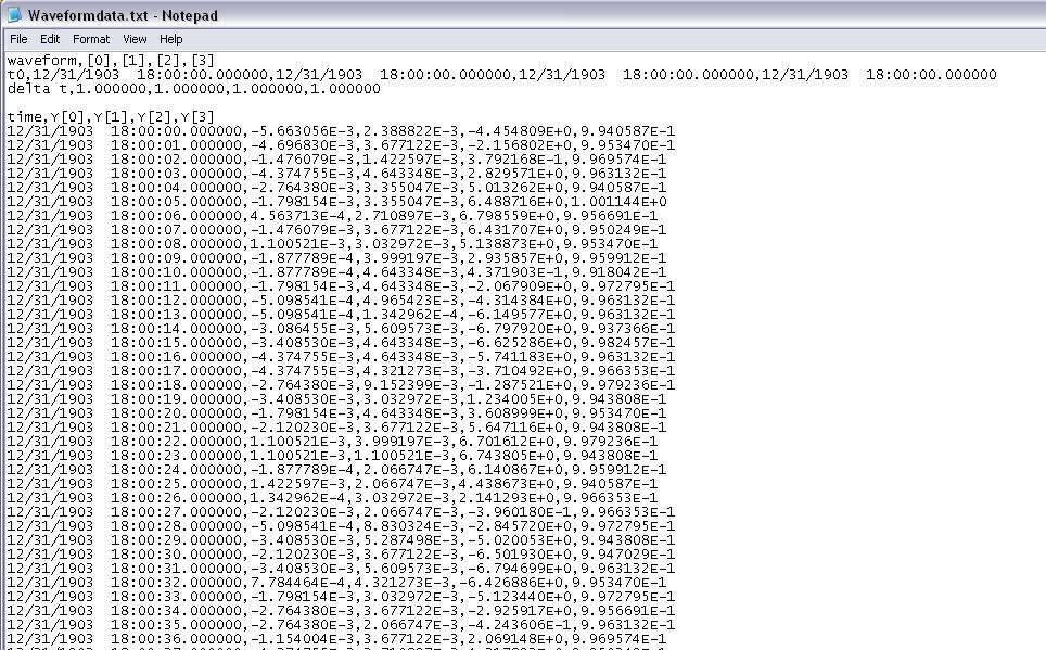
I have a program that reads analog signals multiple DAQmx using a PFI trigger from a DIO card to start the acquisition. It uses a registry to offset and Boolean logic to stop the DAQmx read the loop when the trigger is low. I traced the result to a curve of waveform. I have a 1000 S/s scanning speed. I traced the data to a graph of waveform and eye on the individual data points and it is perfect. Exactly 1 S/s. The problem: when I increase my 5000 S/s scan rate... I see exactly 1 S/s, but the displayed duration of my test data is 5 x more time. That tells me that my graph of the waveform is plotted in fact each data point individual 1ms apart. So basically, there a 1ms all dt in the waveform, and it does not change. How can I get the real dt of the analysis of data here instead of this arbitrary constant? When I look at a text of my waveform data file, I see the timestamp below where I'm expecting something ending like that... 0,0010, 0,0017, 0.0025, etc.. Any help would be appreciated. I'll post the VI if necessary, but other than the trigger power, is a fairly straightforward HERE DAQms read. Thank you in advance.
The time of LV start date is January 1, 1904 midnight GMT. Since your shows up to 6 hours before that, he must be GMT - 6. My horodateurs base are 19:00 31/12/1903, which is GMT - 5. Eastern time zone.
Are you any error coming out after your Subvi waveforms?
You empty an array of waveform data to add. The default waveform has a T0 zero and a detachment of the 1. In the Sub - VI of waveform append inside your Subvi if dt' it does not raise an error, (in fact a caveat being the 1802 error code is positive.). But she proceeds to add data and use the dt and T0 the first waveform which is initially as the default data in the initial iteration. I think that if you start with an array of wavefrom that has the number of channels of the need, an empty array of Y, but a correct dt. Then the dt should be correct. That, or you can put in your Subvi a case structure where the first call, or if the incoming waveform is empty, it is not add and uses only the 2nd waveform.
You have also a little a Rube Goldberg enters your Subvi. It could be simplified as shown in the picture as an attachment.
-
Hello:
Installed Labview 2012 yesterday, daqmx was already installed (9,6) since I used it with Measurement Studio 2012.
LabVIEW does not recognize DAQmx.
I'm using Labview examples and get daq mx errors.
Thank you.
You must install DAQmx after LabVIEW. Since LabVIEW did not exist when you have done the installation DAQmx, LabVIEW required records would obviously not created.
-
photo below explains the problem.

Thanks in advance for the solutions to this problem.
-
Hello
Recently, I changed a series of Structures of cases in a more efficient Structure of the event. However, I'm no longer able to acquire the 4 analog inputs (OR-USB6251) terminals voltage signals with DAQmx Read and store them in a TDMS files. The code responsible for this task 8 ('start running Scan') is the event of the attached code structure.
At first I thought I was calculating the 'timeout' or 'number of samples per ch' incorrectly. However, even when I put them to contant, great values DAQmx Read doesn't seem to work and as soon as the program TDMS files Viewer is empty. One thing I didn't change was moving TDMS close in the Structure of the event when he was outside of the big loop previously. Could this be doing me wrong?
Alfredo
Hello Alfredo.
Of course you have a lot of code here. When you close the TDMS reference in your loop, the next iteration of the loop will be an invalid reference and so nothing will be written to file. Be sure to always close your references outside of your loops.
-
Hi all
I believe that I have correctly configured max I'm trying to use the PXI-6229 device via. When I try initialized, I get the following error:
The primary error: (Hex 0xBFFA003D) could not find any channel or repeated capacity channels.
Clues about what means error?
Thank you
Manesh
First of all, you'll have more help in the appropriate forum. This seems to be a problem DAQmx and their forum is here: http://forums.ni.com/t5/Multifunction-DAQ/bd-p/250
Secondly is this help: http://forums.ni.com/t5/Switch-Hardware-and-Software/NI-SwitchExec-with-3499-and-IVIDriver/td-p/1827...
Finally: You can communicate with the MAX card? Or is the occurrence of the error in MAX? What language do you use to talk to the card with? Using IVI? If you are using LabVIEW or CVI then open examples of shipping and test them with this card.
Kind regards
-
Problem after update DAQmx 15.5.1
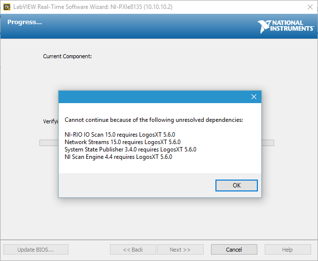
Just updated DAQmx 15.5.1 on the host computer. Try to use MAX to update the DAQmx software on the PXI system at 15.5.1 as well, but I received the following error message:
I would appreciate any suggestion to determine this. I'm using LabVIEW 2015 SP1.
I use the OTR (pharlap) on the PXI system.
I think that MAX has some issues to resolve dependencies. I actually fixed this problem manually set these 4 packs of resettlement in MAX and the update of DAQmx. MAX will become meaningless and crash if I was not choosing these packages in a certain order, so it took me some trial and error. In the end, when I select all packages associated update DAQmx together these 4 packages to reinstall, the installation process would go through.
I suppose that if I format and reinstall the system on PXI system, it can also work, but I wasn't looking at it.
-
Problem with DAQmx Schedule VI (sample clock)
Hello to you all,.
I'm new to this forum, please bare with me. I have some experience with LV, but I am relatively new to data acquisition projects. I use LV2009.
I want to make sure that I use the hardware timing (instead of software distribution) in my project so I followed some of the threads here as sugested to use DAQmx Schedule VI. The problem is that no matter how I set the system I get the same error-200300 invalid calendar
type.The project is simple. I encode with 1000 pulses per
Rev and it is mounted on a shaft of a turbine water goes thru. I'm watching the frequency
and so the rotation of the shaft which tells me that the amount of water flows through the turbine. In the end, there will be 2 channels
by every encoder and ~ 3 encoders (turbines) total and calibrated the main meter that will give me constant impulses and all encoders will be compared to this master frequency.I'll use PCI6602 DAQ, but
now, for the development, I use USB6221. Let's say that the
frequency is between 500 Hz and 10 kHz. What I am doing wrong? Or maybe better to ask - what would be the right approach for this project?Thank you
Marty
Hi Marty,
It seems that your question is already answered here, but Jason is correct that the 6221 neither the 6602 support a clock sampling for frequency measurements.
As Jason mentioned, your best bet is also likely set the mode of synchronization for "implied". This means that the frequency value is sampled at the end of each period of your input signal. In addition, a solution that is clocked by the software (On-Demand) might be acceptable.
X Series DAQ devices allow an external sample clock to use for frequency measures (described in the Manual of X series). Frequency of sample-clocked measures are useful in very specific
circumstances, but it does not seem that you need this feature based on what you've described so far.(621 x) bus-powered M series can also be configured to use an external sample as the X series clock but do you not have the same features described in the manual of the X series.
I hope this helps!
-John
-
Communication problem 6210 hardware DAQ with DAQmx 9.2.3 (Err 88302)
I would use NEITHER-USB-6210 with DIAdem 11.1 under Win 7 Home Premium. DAQmx software and supplied drivers are version 8.6, but does not support this DIAdem 11.1 (DAC-NOR-DAQ interface did not show any existing signal). So I decided to update software DAQmx on latest version 9.2.3 which should solve this problem. After installation, all previous configuration items, MAX moved well and DIAdem DAC block indicated all signals with success but start of acquisition and measurement is impossible since. After firmwareloader establishes the material connection seems to be running, but any attempt to transfer data or start any function Max raises failurie event-88302 "an internal error has occurred." Anyone help me please?
Dear Mr. Varga,
After that the PC was clean from previous installed everywhere DAQ and new installation repeated once more, problem has been resolved and now the system is fully capable to work with DIAdem, as well as with the Net. request.
Kind regards
Milos Riha
-
problem reading DAQmx using Measurement Studio 2010 (even with examples OR)
Hi all
I'm reading the voltage using a map of NOR-DAQ-6211 with Measurement Studio 2010 SP1 V9.1.0.204. using Visual Basic .net 2010.
When I create the task of data acquisition with the measurement studio Wizard, (Assistant DAQ) everything works fine. However, when I try to create my own task player in looking over the "ContAcqVoltageSamples_IntClk" everything I read is a value in the range of Vmin to Vmax (or to Vmin Vmax) and then she stays there no matter if I change my diet. Vmin and Vmax does not yet match my values of voltage. (It acts like that on my application and example of OR) I guess I missed a few initial settings. The config of AIChannel in two projects (manual task and Augo-Gen) use AIChannelConfig.RSE (I tried other options, but no luck).The only wiered thing is that when I open examples of projects, VS does not recognize the object references of NOR. Workspace names DAQmx. When I check the references, it shows that it does not find the reference to NI.Common. To make it work/compilation, removed from the solution and I again added. (I don't think this is related, as it seems that there are available tensions but not read correctly).
The other thing is that my input voltage is 3 or 0 volt. When you use the manual DAQtask, when I toggle the voltage, the values displayed change momentarily the order of 0.001 Volts and then go back to their previous values of Vmax and Vmin.
Is there more information I can provide?
Help, please
Thank youYay! I just solved my problem,
From the first moment I knew there was something fishy about this AITerminalConfig thingy! I made two errors:
1. in the code example Configuration AI is encoded: CType (-1, AITerminalConfiguration) that caused the code example does not work for all channels to HAVE it
2 - also, I have in my code, I had put this config to the correct value, but I was checking ai0 all the time while the signal was on another I. I was under the impression that since the example does not work for all my channels, then probably my code does not work as well.
If after changing the line in the example for the correct terminal configuration settings, he began working for the AI number I was looking for too much and I found that my code worked for my AI # correctly from the beginning. I wasn't just to see it!
-
DAQmx 50413 error problems & meter
Hello, we have recently set up our PCI-6229 map on a new computer running Windows 7 and have upgraded to LabView 2009 8.6. Our vi already functional to count the photons closed now returns a NaN value instead of the counts and, occasionally, displays an error message: "error-50413 occurred at DAQmx Read (minimum 1 D DBL 1Chan NSamp) .vi:1 ' which appears first of all inside the integrated_data_taker6229_v2.vi and spreads to the integrated_gate_mover6229_v2.vi.
Others that the move to a new computer and updated the software, all remained unchanged (IE channel assignments). Everyone has experienced difficulties with their vi after a software upgrade or moving to new hardware.
Any help would be greatly appreciated!
Thank you
bftm
Hello
From the looks of your error, there is a physical error that occur on the plateau that is separate from your software. Looking for information on my side, there are a few things to try which have been known to solve the problem.
You have another PCI-6229 map? If you do, try to Exchange cards to see if there is a different result. This error sometimes occurs when the PCI card is not sitting properly in place, try so take the card out and clean the contacts, then place the card back in the system in a different PCI slot.
If you have another PC system, try installing the card and software in it and see if the error persists. Most of the time, the question is specific PC, and the PC with another PC of switching problem solves the problem. Because you have recently changed to PC, I'm inclined to say that there may be a problem with the PCI on this PC bus, or the way the card fits in that the bus is not quite correct.
If all else fails, a return for repair can be done on the map.
-
Problem with the release of DAQmx not adjusted
Hello
I'm trying to convert a recording program generally written in Labview to exit of the floating numbers of unsigned integers. I use the DAQmx read where I choose the unadjusted output (2D U16 NChan), the Board of Directors is a PCI-6023E. I have the program running, but the output is a little strange. The input range is of +/-10 V. For positive voltages I get integers from 0 to 2047. For negative voltages I get integers from 2 ^ 16-2048-2 ^ 16. I want to have is of course 0-10 V and 4096 for 10 V. I'm looking through the different options in lu DAQmx etc. without a bit of luck. If someone has an idea that could shed some light on my problem it would be greatly appreciated.
Best regards
PAL Egil
The type U16 represents numbers as unsigned quantities. In particular, I16 (signed integer) value of-1, hexadecimal FFFF, is 65535. If you save the values as I16 (assuming this is possible with your device) or simply convert (using the auxiliary palette of Conversion of the digital palette) I16, I think you get what you expect.
Bob Schor
-
DAQmx LabVIEW 7.0 Wizard problem
Hello, I tried to search for this problem a few times, but I couldn't find a thread that matches my problem. I only started using LabVIEW yesterday so please forgive my inexperience if I do obvious errors. The problem I have is this:
I have two computers, two LabVIEW 7.0 running on Windows 7, with a card OR-DAQmx (PCI 6221, driver version 9.3) and the other without. Without the card has MAX version 3.0.2 and the other has the latest version (4.8). So far I followed the tutorials in the 'Help' files called "Getting started with LabVIEW", using the machine without the DAQ card. In the fourth chapter he speaks of an Express VI entitled 'DAQ Assistant' which is in the range of I/O functions window. When I try to enter a block diagram VI, rather than open the wizard, it hangs on loading splash. This, I expected when the machine is not material.
Then, I started the other machine, who owns the card installed. I opened MAX, do you have the self-test, checked the test panels and made automatic calibration. all reported ok. When I open LabVIEW, however, all functions related to hardware DAQ is missing from the palette. I tried rolling back the drivers version 7.1 and MAX to 3.0.2 in the hope that reproduce the condition on the other machine would fix it, but no luck there now I'm at square one without knowing what to do. I really need to be able to use this card with LabVIEW for my project, any help would be greatly appreciated.
OK guys, I have now Windows XP running in a virtual machine on the computer with the installed data acquisition card. Outside the Virtual Box, I still have driver MAX 4.8 and 9.3 versions and map is available on the tree of devices to the MAX, as before. Within the VB I use LabVIEW version 7.0 and DAQmx version 8.1 (MAX 4.0.3.3003) drivers as suggested, but the map is not appear in the device tree, even if I tried refreshing several times. To create news... window has no option for a card PCI-6221, only for PXI and SCXI hardware. Clues?
Maybe you are looking for
-
KD-49X8005C won't turn on without reset
Hello! I recently had a KD-49X8005C and have been very happy with it regarding the functionality and image / sound quality. It is a brilliant TV. However, there is a really strange problem. Many times, the TV will not come. I press the button on the
-
"Configuration of the Windows updates...". 0% complete... »
When I turn on my computer the message "Configuring Windows updates... 0% Complete... Do not turn off your computer"appears, I expect him to 5 minutes and then it says Setup failed. What is going on? It takes me ages to get online! I have Windows 7 S
-
Sotitutivo disco preventivo Equallogic
Buongiorno, UNO dei nostri storage Dell EqualLogic PS4000XV (serial number JMMKWP1) line a disco sotitutivo da 300 GB, SAS, 15K rpm, 3.5 ". Lo storage e fuori co. Could gentilmente fornirmi detailed by the sostituzione? Grazie.
-
I tried to configure Media Center for Internet TV and Netflix. I have Setup several times and attempted to manually download the updates. So far, neither option appeared on the menu screen and I repeatedly received an error message when you try to do
-
BlackBerry Smartphones the "BOLD" mode standby.
So I just found out that put my BB "BOLD" in the case puts the phone in standby mode and saves the life of the battery (it is fine... I threw my case the first day because I carry the phone in my Pocket ). My question is this: if I play with the phon