Reference library of digital waveforms of SPI for LV 7.1
Hello
I'm using LabVIEW 7.1. I want to implement SPI communications on a NI HSDIO (PCI-6541) device.
The SPI Digital Waveform Reference Library (http://zone.ni.com/devzone/cda/epd/p/id/6163) is available for LabVIEW 7.1? Someone at - it successfully he converted from 8.2 to 7.1?
The screws are also available under the reference Application Communication Protocol series for digital devices of waveform page (http://zone.ni.com/devzone/cda/epd/p/id/6200) available for LabVIEW 7.1?
Any help would be appreciated. Thank you.
Hello
Unfortunately there is no simple way to convert libraries back to the 7.1.
My suggestion would be to download an evaluation copy of LabVIEW 8.6
You could use the trial period to open libraries and use as reference to re-create what you need to in 7.1.
Hope this helps,
John
Tags: NI Hardware
Similar Questions
-
How to record a digital waveform with timestamps for each sample?
I am generating a digital stimulus and capture the digital answer using 6552 HSDIO. The captured response is data digital or forms of digital airwaves.
I want to save the captured digital answer and save it in a file in spreadsheet showing the timestamp for each sample. How can I go to a digital waveform to a worksheet that contains all samples and timestamps for each sample?
Comvert digital to analog is just the wrong function. And when you converted to U8, you just threw the calendar information. Try the code below. He puts the time in a single column. If you want to only two columns, its an easy mod.

-
Digital waveforms of SPI with PXI-6552
I am trying to follow the following tutorial about the PXI-6552 module: http://www.ni.com/white-paper/3671/en.
This is the example that I am referring:
You can also use the data Active event to control the relative delay between the response data and the side assets of the sample clock. For example, you can export the active data on PFI 1 event and send it to the PFI 2, which can be configured as the source of Start command acquisition, as shown in Figure 8. You can export the generation of sample DDC CLK clock out and adjust the STROBE acquisition sample clock.
Figure 9 shows a LabVIEW program that configures and outwardly carries the data Active event and the sample clock. The functions marked with an arrow carried out additional system requirements.
Hello MrHappyAsthma,
I'm looking at your code, and I see that you have two sessions of acquisition while the example has an acquisition and sessions of a generation. This could be the reason for the error.
The digital data control are done right click on the front panel, then go on modern > I/O > digital data.
I hope this helps.
-
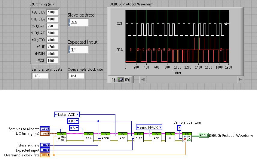
Digital waveforms I2C library sync settings
Does anyone know how the consolidation of the 'I2C Timing (ns)' is in the following code? This is an abridged version of the example of the VI "HSDIO I2C - hardware Compare.vi ' downloaded from here. It uses the I2C Digital Waveform reference Libarary.
Time on the x axis doesn't seem to be any help, and the front panel settings are very cryptic in their naming system. No one knows what these numbers mean and how it correlates to real time (dt) between each point?
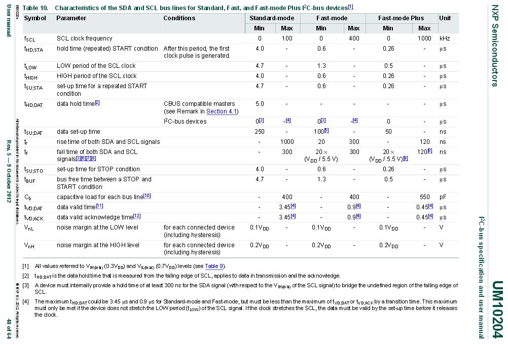
I finally found where the parameters are specified. They can be found in the specification UM10204 I2C - bus and manual.
Under the current revision 5, found in table 10 on page 48:
-
Extract a channel of a digital waveform
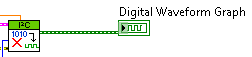
I use the I2C Digital Waveform reference Libarary to create a WDT which consists of two lines/channels. I was wondering how I could extract/remove a channel, the wave form and how can I add/merge signals tracks in a single WDT? I looked around for the screws, but nothing seems to work with the WDT.
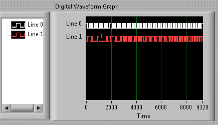
Right now my WDT is like this:
How can I get these two lines in separate WDTs? And then how would I be able to merge them again? Naturally, I don't want to just remove them and merge them, but that would be an example of good practice to demonstrate.
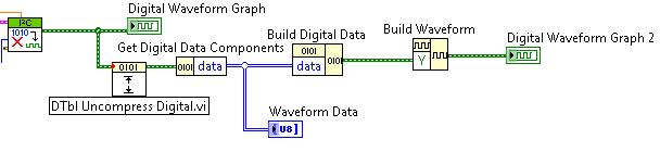
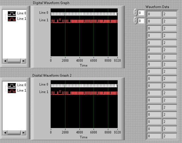
After much trial and frustration, I found a way to do what I was looking for. It is not the most elegant, but it works!
That's how I extracted the two strings in an array and then merge to recreate the original graph:
* Note: The reason why there are 2 in the waveform data table is because my waveform contains 0 and Z instead of 0 and 1. The three States Z corresponds to the 2 digital.
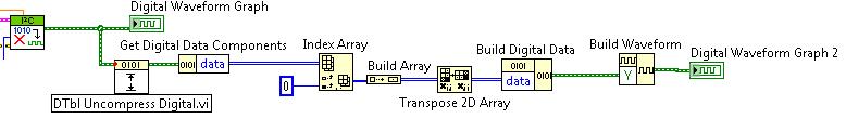
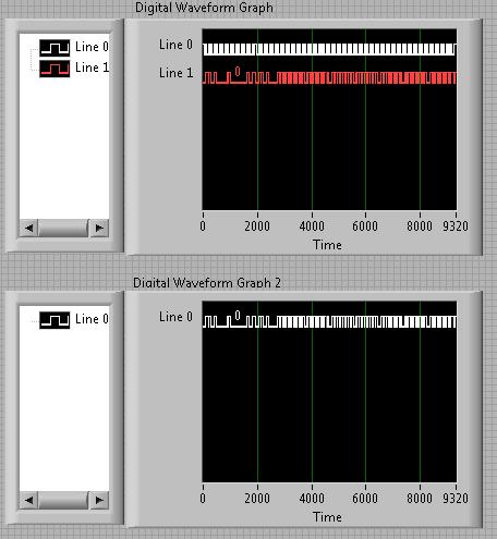
I even took it a little further and extract a single line. This could be changed to extract any line and eventually merge your own custom signals:
-
Continuous output of digital waveforms on PCI-6602
I use 6602 PCI to get a continuous 1 MHz square wave output of DIO1 ~ 32 sequentially controlled by LabVIEW. I Ctr0 to generate a clock 2 MHz and used Ctr0InternalOutput as a source of sample for DIO1 clock ~ 32. I have attached the code and the texture as follows.
The code works fine on PCIe-6251 and digital waveforms of 1 MHz is very stable.
But when I run on PCI-6602 I got an error-200077 (you asked for: sample clock; you can request: on-demand).
6602 PCI does support material timing? I found no information about this its specifications. If she can't, how can I avoid this problem and get what I want? Thank you!
Yi
Version: LabVIEW 8.2
hardware: PCI-6602
Hello
Have you looked at the specification for the 6602?
http://sine.NI.com/NIPs/CDs/view/p/lang/en/NID/1123
Click on "specifications". Scroll down to "digital i/o". Watch "Timing". It clearly says "software".
The DIO lines on this Board are not timed by the hardware. They are clocked by the software. The data sheet that explains very clearly. That's why you see the error clock sample - that the Council can't stand DIO clocked by the hardware.
The 6251 supports clocked by DIO material, so why your code works very well with this Council. You can do the generation of signals with a 6602.
Hope says.
d
-
Generate a digital waveform like memory on PXI cards
Hello
I'm looking for a way to send a large digital waveforms using a PXI digital signal generator. I saw DIO HS cards, but their memory is smaller than the files that I want to transfer. My understanding is that the PXI backplane bandwidth 132 MB/s. So, I shouldn't be able to stream a digital signal from the memory of the card that is slower than the CPU? For example, 50 Mbits / second (equivalent to only 6.25 MB/s)? However, I think I understand after reading their textbooks is that you cannot continuously transmitting a large waveform of the processor memory file, you must transfer the file to the memory of Council first and then transfer that out.
Does anyone know if there is a way to have a flow of digital signal generation card an arbitrarily large directly from memory to the processor of digital signals? Or, what is the fastest card of pxi digital signal generation that does not require the storage of Council first files?
Thank you
Isaac
Hello Isaac,.
Take a look at the following area developer.
NOR-HSDIO Stream from disk (generation) using Win32 file IO
Note that you will not be able to take full advantage of the maximum rate of update HSDIO devices, because the data must be transferred in a bus. Some other considerations are the width of the data as well as the HSDIO device you select, which may depend on other requirements not related to the size of file or waveform (for example the standard voltage or whether you need hardware compare). For more information, take a look at the developer following items area.
Data streaming of Architectures in the PXI systems
The use of National Instruments Logic Analyzer and generator of test patterns SolutionAdvanced features of e/s high-speed digital devices White Paper Series
-
Can someone tell me how to extract a part of a digital waveform?
I am trying to extract a part of 2 analog waves (using the http://zone.ni.com/devzone/cda/epd/p/id/4149 for example) analog signals is synchronized with a digital waveform. I need to extract the same portion of a digital waveform. Can someone tell me how to add the digital extractor in the example above?
Hello
Here's your extractor example slightly modified in order to add the digital data extraction.
The principle is exactly the same, the tricky part is how to get digital data which is different from analog data.
You can also add nodes property to identify the value read on the analog graph sliders on the digital chart.
Kind regards
-
Table 1 d of digital waveforms
I have a table 1 d of digital waveforms and I need to work with the data. I can't get the 'mass' to work with any function table or any other type of function also.
I need to be able to convert these so I can find a particular value in the table.
Thank you.
So you're just trying to get inside the matrix? Use a loop For or an Index Array node.
-
Count the number of 1 is present in digital waveforms obtained by converting the pulse signals.
Hello
I use Analogtodigital.Vi to convert the pulse of the sequences in digital.signals.I am able to get the representation of digital waveforms of impulses.
But how to count the number of 1 is present in the converted digital waveform. I want to count the number of 1 is present in the digital waveform converted.
Thanks in advance.
Have you tried the block scheme of similar to the Digital.vi of opening?
It creates an array 2D uncompressed 1 and 0, which is the binary 16 bits A/D conversion of each element in the array Y of the input waveform. You can use the DWDT digital Array.vi Boolean to convert a 2D Boolean table. Then convert Boolean values to 1.0 and summarize the array of integers. The sum must be the number of 1 bits in the digital waveforms.
Lynn
Note: The VI attached is saved in version 8.6. When I have it saved for the previous Version a warning was generated about the possible differences in the versions. Let me know if it doesn't work, and you are using which version of LV.
-
static/digital waveform output and low frequency measurement of voltage - SMU-6358
Hello
1. I have an attached VI [digital_voltage_output] who must generate a logical true or false static state in the output of the device/port0/line1 Word to say. When the VI works I click the button several times, but nothing happens to the port0/lines1.
2 such a thing [digital_voltage_waveform_output_square] if I'm trying to generate a digital waveform to pin the same with the waveform generating VI. If I connect a waveform chart to the output of the generator function VI, then the chart will show me the good waveform I want, but still nothing is written to the text file.
3. I have read the manual for the X series cards, but it remains unclear for me a little how to things of the road in LV I have a measure of the frequency measurement VI low frequency that I downloaded. It offers me the ports for the supply frequency - ctr0, 1, 2, etc. As far as I'm concerned the PFI ports are responsible for these types of actions. How can I find out the LV that I want to connect say ctr0 and pfi0? »
I use LV 8.6.
Thank you
Kriváň
Hi Kriváň,
The problem you had with the choice of a specific digital line as a physical channel, is that the control that was previously used in this example was created for a data acquisition task that uses a whole port rather than a specific line. I was able to overcome this problem by removing the control and recreate. The control now gives you the option to choose the specific digital lines e.g. port0/PXI1Slot2/$line0.
I was also able to overcome the error of-200802 you mentioned. I was able to do this in a real constant of wiring at the entrance to auto-start the VI DAQmx writing then remove the DAQmx beginning the subsequent code VI. The modified code is attached.
I hope this helps.
Best regards
Christian Hartshorne
NIUK
-
Could someone tell me how to convert the digital signals in table 1 d of digital waveforms
I use 9474 for drving an engine. for that I have uses 2 ports - to activate and another for running. These signals in the form of Boolean values. I am to convert these signals to a table and since iam doing a digital waveform. but when iam connecting these to the module 9474, it show an error "source is a digital waveform and sink is 1-d array of digital waveform... any body can help in these issueee please...»
Pop - up on the thread and choose Insert...
Build the table.
Ben
-
Attributes of digital waveforms, LabVIEW 8.5 freezes
I have 6 cards LVDS, 16 analog inputs by card. I want the user to select a subset of the 96 channels available for display. The attached code causes my pc to freeze. Not always, but sometimes when I switch between the selection of channels. Select either Chevron1(24-channels), Chevron2(24-channels), Chevron3(24-channels) High-Power(3-channels) or enter your own strings as string from 1 to 96.
This problem can be connected with the bug of attributes known to digital waveforms. If all goes well, my code is self-explanatory.
See post http://forums.ni.com/ni/board/message?board.id=170&thread.id=349313
For more details of the refrigerator used in the attached code.
Hi bmann2000,
I don't think that we will be able to get the 8.6 control works as you want because of the CAR. However, I have a suggestion that I have attached to this message. I used an array of strings to create indicators based on your logic of origin. It is not as clean or well tidy as your desired result, but I think it might be a solution. This is a screenshot attached. The VI is saved to 8.5. Despite the name of the file to the contrary.
Let me know what you think,
-
How can I write a digital waveform to the digital output (traditional DAQ)
Hello
I use a NI 6023e, PCI, with 8 digital outputs. I generated a digital waveform. How can I write for a specific digital production line now?
I only have Labview 7, so I can't use DAQmx.
Thank you very much
-
Generate digital waveforms of high frequency
Hi all
I have some problems. Today, I am generating several digital high frequency waves with my DAQ (PCI-6251) card. The duty cycle of the waveform must be adjustable.
The required frequency is 100 kHz.
To do this, I have tried several solutions:
(1) I used counters in the acquisition of data to generate waveforms, and it worked fine. However, I have only two counters. In my application, I need to at least three waveforms with different cyclical report;
(2) I used a 'loop' and structures 'case' in labview to build the model of waveform and then feed them to the digital I/o. However, the problem with this solution is that the frequency of the wave generated cannot be high.
(3) I used a 'digital' generator in Labview to generate waveforms and then feed them to the digital I/o. In this case, the time base is from an external source (200 kHz). However, with this solution, the cycle is not adjustable.
Please give me some advice on how to make these waveforms. Your assistance is appreciated.
OK, so I may be wrong, but after mucking around for a bit, I realized that the regeneration should be automatic - in other words, if you a pattern to the right and then just leave your VI work in a while loop, you will find that the generation is continuous. Discover the correlation dig write metered in the finder for example Labview. You can leverage this as you get the cyclical report you are looking for. You can split the signal down what you write a single period consisting of a series of 0 and 1. In other words, if you want a wave of 100 kHz with a cycle of 20%, you write a pattern of digital waveforms a 1100000000 at the rate of 1 MHz. Using this technique, the resolution of the cycle will be limited by the on-board clock speed (80 MHz = 0.125%).
Let me know if this makes sense - I am unable to reproduce this on my desktop and have never had to do this before.
Cheers, Matt
Maybe you are looking for
-
Stop during updates, now it does not start!
Hello I have a HP Pavilion dv7-6c95dx, he stopped during updates last night and now it won't start. Check the power cord, its fine. Battery is fully charged. Thoughts? Ideas?
-
The upgrade of the power supply.
I recently bought a vido GTX580 and discovered after I got that my wimpy 250 watt power supply will not manage it. The card requires at least a power of 600W at 42 amps on the 12V rails. The card must also 8-pin and a 6 'PCI Express' connectors from
-
I am looking for camera wizard compatible with toshiba satellite a300
I am looking for camera wizard compatible with toshiba satellite a300
-
Pavilion dv6-7014nr: Synaptics touchpad has ceased to be recognized! NEED HELP URGENT!
I was using my laptop for general browsing today and she left open for about half an hour to attend to other things, but when I came back, I found that the touchpad had stopped responding completely - the two buttons and the trackpad. The touchpad no
-
The upgrade from Vista to Windows 7 I just bought Windows 7 upgrade Windows Vista. I get the error message: operation is not supported on this platform. What should I do to get this latest version in my computer?