resistance measurement USB-6009
Using the DAQ 6009 to measure the resistance resistance?
Sure. You just need to know what you're doing. In addition, it depends on what precision you're looking for.
Tags: NI Hardware
Similar Questions
-
measure resistance with USB-6009
I am measuring the resistance of a photocell using the USB-6009 case. There is an option of "resistance" in the DAQ assistant, but it does not display the values on the right. Here's what I do:
Connections: GND - photocell - ai0
I'm really not sure if this is right, but I assumed that he could measure the resistance as a multimeter. I have not tried doing a divisor of tension and using the Ohm's law.
DAQ Assistant settings: I 'add channel' by using the more blue and choose "resistance". Then, I chose ai0 under USB-6009. I set the max and min values and read it all the time. First problem, playback is generally negative and it flickers a lot. I read about - 1.3 k when I do that with a k resistor 10 regular (not a photoresistor)
Obviously there is something wrong, but I'm very new to all this and cannot figure it out by myself. Any help would be much appreciated.
Thank you!
The 6009 cannot measure the resistance as a multimeter unless you can prove that a current as the wizard by default source is set to. In itself, it can measure a voltage. Then, use a voltage divider.
-
Measuring current using USB-6009 with a rheostat shunt resistance
Hi all, I am an electronic engineering student doing my final year project. I am able to measure the current and voltage of a 9V battery, but not knowing the method that I use if it is correct.
For the voltage, I have no problem getting it. But for the current, I connected a resistance of 1 k in parallel with the battery. When I run the program, I have a 9mA for battery. I understand when you use the DAQ assistant, for the installation of measuring current for USB-6009, that I need to specify as "external" shunt resistance and shunt resistance value (which is 1 k for the above experience).
So, my question is when I use a rheostat as shunt resistance, what value should we indicate as a rheostat is a variable resistor, so it doesn't have a fixed value.
Or the dimmer cannot be shunt resistance?
Really need help and thank you for the reply.
-
measurement of current with usb-6009
Hi, my name is hung and I am a student in electrical engineering... I'm doing a thesis that the project using Labview and acquisition of data NOR UBS-6009 to simulate the function generator, Oscilloscope, Digital Microsoft (DMM)... and now I'm simulating DMM. I managed to measure the voltage and resistance which i use voltage divider method, but I encountered a problem with the current measurement. The problem is the USB-6009 to measure use the current, it measures an incorrect value. I tried to use the current CQI 0-20mA Sample.vi example but it always measures an incorrect value. If NI USB-6009 supports for the measuring current? Is there a way to measure the currents using USB-6009? Please, help me. This thesis project is so important for me. Thank you.
Hung,
Since you are a student in electrical engineering, I'll show you how to know the answers to your questions.
1. review the specifications for the USB-6009 case. In particular look at the specifications of analog input.
2. How would you measure current if you had only a voltmeter? Use the same method with the USB-6009 case. (Tip: apply the Ohm's law).
General comment: when using any measuring instrument, always consider maximum permitted values at the entrances so that the instrument is not damaged
and the measure is accurate.
Let us know how you do.
Lynn
-
Problem: The differential mode, measure 1.4 V, USB-6009
Hello world
I am able to charge and discharge the two capacitors, individually.
I use the USB-6009;
Two capacitors, two charts, two analog inputs (AI0 +, AI01-) and (Al1 +, Ai1-);
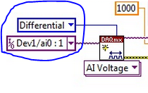
I have configuredin differential mode; Ok
Problem:
When a capacitor is switched off, it measures 1.4 V
Try to correctly set the task - run the DAQ Assistant to create the task

Dev1/ao0 would be much better - Oh, and now that you take the wizard open-Do on the wiring diagram, it offers you

For the PREMIUM of 6009 task mode AI0 is + AI3 is - and you only reserve reserve explicitly AI0 (AI3 line is reserved by seleting the + line in the channel and the declairing it is differentiated)
And give the task/channel a significant name of "MyCap1Discharge" would be useful...
Now let's talk about your electrical engineering:
The input of the 6009 impedance is 144kOhms the resistance of discharge 1MOhm becomes useless as soon as you connect the control AI 6009.
-
Typical values for the external resistance of pull-up on a line of output digital NI USB 6009?
Hi all
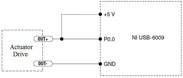
I use a digital line on a USB-6009 to control a SSR by the attached diagram (in the manual USB 6009). I don't have access to a variable resistor or box of 10 years, so I'm hoping to get a good approximate estimate for the value of Re. When I connect the CRDD at a 5V supply, it shoots 8.2mADC when closed.
Any suggestions? Is there any other information I can post for help with the guestimations?
Thank you!
I have found an old box of decade Heathkit and understand the degree of correct resistance 100 ohms.
-
How to measure the digital output of the linear actuator on USB-6009?
Hello
I am a new user of Labview and need help to measure a digital input signal.
I have an actuator Bimba Original line electric with a motor continuous integrated with encoder, drive and the controller. The drive has a programmable digital output that I put as a tachometer output that emits pulses of square wave 100 per turn of the engine. I put the engine to make a total of 56 rev in 22 dry. I want to measure the speed of motor rotation labview real-time and synchronize it with a few other analog input signals. I wired the actuator for the USB-6009 case as shown below.
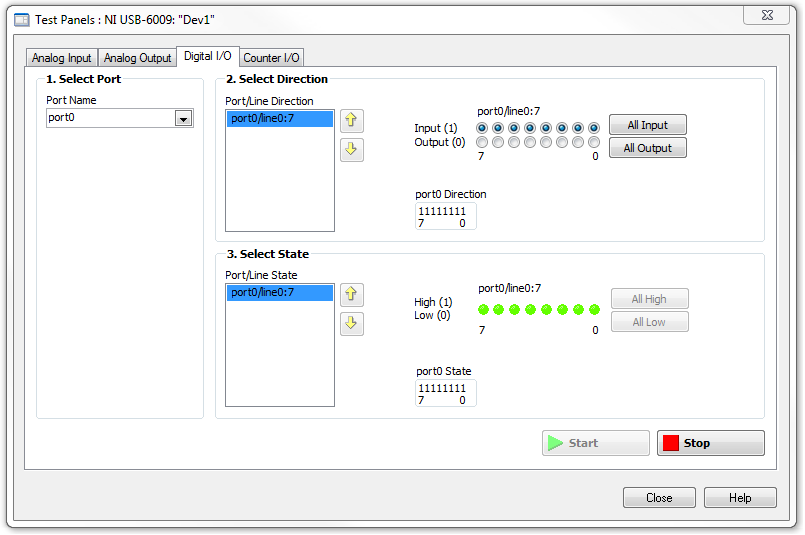
I opened the test i/o digital USB-6009 Panel and fix all the lines of port 0 as inputs. However, when I click on start and run the actuator, p0.0 led flashes, as indicated below.
Shouldn't the led blink in response to revolutions of engines?
I want basically to collect the drive pulse signals and convert them in rpm on labview.
ahsan2 wrote:
I have it wired correctly?
It would help if you do not attach the HIGH signal. Remove the + 5V in the circuit.
-
USB-6009 software simultaneous timed output analog
Ladies and gentlemen,
I worked on a LabVIEW interface to a potentiostat I designed and built. I'm not very experienced with LabVIEW, but do they have experience with a variety of other languages (I had originally intend to use an FPGA for this, but he has been asked to write a LabVIEW VI first) programming.
The goal:
I want to output a voltage (initially consisting of ramps) signal and measure the voltage with an operational amplifier configured as an ammeter of feedback (using resistance feedback and voltage value to calculate current) connected to an electrochemical cell. The resistance of feedback is selected by using an automatic selection function (although I wrote a version prior to manual control) as TTL values using the DAQ Assistant to select relevant MUX channel outputs. I then try to save the data in a spreadsheet.
The problem:
I use an acquisition of data USB-6009, and I know that there is a hardware clock. Read all about him seemed obvious, the best way to the waveform of the output voltage used DAQmx package to define a function of writing in a loop that is clocked by the software. The problem I have is that I can't synchronize the output to the input with reliability and I have also some errors related to resources DAQ being reserved (error 50103). I think the way to solve this would be to convert every equivalent DAQmx DAQ Assistant and try to group their execution - this is where I fall. I tried to write a simple VI who shared a loop clocked by the software to read and write but had problems related to the value of min HAVE (error 200077).
General issues:
How I begin the process of read/write (with a Boolean switch) is very weak and doesn't feel not robust. Ideally, I would like to some form of indicator to warn the user when the read/write process is running and when it ended.
My error handling is terrible, but I find no big thing to read about the basics.
I use only a sequence of no and I think I should have more.
Once I hit the beginning, VI requires the file name for the worksheet - at first, I was afraid that data would be entered correctly, but I think it's okay because the file is generated and then changed. It would be better if the user asked for the name of the file once completed the data collection.
Any suggestion or help would be greatly appreciated. Thank you in advance.
Sincere greetings,
Julius
The hardware supports timed 6009 entry analog. Even with the 1Samp mode, your code could be simplified with a single task and several channels (dev1\ai0:1). Then use Nchan 1Samp.
-
Hello
I use several USB 6009 units and with some of them seems to have some lag in differential mode, I with 0 to 1V range. Grounded the two terminals with resistors as shown in the tutorial OR «wiring field and noise review...» "seems to fix the problem for some of them, but for those that I have not the slightest compensation first, the ground gives me offset. Can someone please suggest?
Thank you
DS
DS,
Please submit your question in the Forums of NOR. Are you trying to take a differential measurement? What features are you try to measure it and what channels the drop-resistance work with and what channels do they not work with?
-
What is input equivalent circuit of USB 6009 PFI0
The entry USB-6009 PFI0 is the same the analog input circuit stated in manual mode?
I use the PFI0 to trigger a measurement of voltage and it works a lot using a HP function generator.
When I try to drive the low entrance with my circuit looks like there's a pull up resistance to + 5 on the entry of PFI0 terminal.
This entry PFI0 will accept an output of comparitor from 0 to 15 volts with being damaged?Kip
Here is my solution to operate the PFI0 TTL digital input using a CMOS comparator.
I use a 2N4401 npn transistor.
Connect the transmitter to the ground terminal.
Connect the manifold to the PFI0 (there is a pull-up internal resistance to the 6009).
To connect to the Base of a voltage divider that limits in input current and decreases the CMOS voltage to TTL levels.
In my case I'm going to 0 to + 15 so my voltage divider is 4.7 k and 2.2 kohm to fall to 0-5 volts.
It is an Inverter circuit so your sense of trigger will go head on falling edge, or vice versa.
I hope this helps someone.
Kip
-
motor current by using NI USB-6009
Is there a way to measure current of a motor with the NI USB-6009 case? I understand that I must use I = V/R. But it seems that with this concept, I would have losses for the engine, so I used a small resistance and measure the voltage across it. I'm trying to get a reading of the Spike current with a voltage to an engine No. Thanks for the help.
-Nick
The shunt would be just to go online with the engine and measure the voltage drop across the resistance.
Eric
-
Is it possible to install a usb-6009 Dasylab box?
I need to install a usb-6009 case in Dasylab, but Dasylab not recogise daqmx devices, or what it looks like.
MAX, I see I have traditional NI DAQ installed (7.4.2f3), but the usb devices are listed as daqmx devices.
Is there a a way to deceive Dasylab seeing my device?
I usually work in Labview, but now I need to replicate a measure of a colleague from Ethiopia and Dasylab is confusing at first.
Wouldn't be easier to use a pci card (we pci 6220 available)?
Max version4.3.0f0
8.6.1f0 DAQmx
traditional OR daq 7.4.2f3
DASYLab 8.00.00 since 2004, old, I know)
LabVIEW 8.2
If you create a task OR-DAQmx with the device, DASYLab should see it.
There is a download for the driver OR DAQmx for DASYLab 8.00.04 to www.dasylab.com
http://DASYLab.com/content/driver.php?action=filelist&SID=33
We can only provide active support for current versions of DASYLab (V11 and V10), therefore, it is not much of help available.
-
OR USB-6009 and Tek TDS2024C comparesment
My apologies if this topic was already discussed, but I searched through the forum and manuals and can't find anything.
I have a problem with measurements in parallel with TDS2024C NI USB-6009 and Tek.
I measured the noise high frequency on 10 s window.
I used the data logger with a frequency of 40 kHz connection in parallel with TDS2024C (which reached 250 Hz on 10s window) and got very different results.
On the attachment figure, first signal comes from screenshot of scope data and the second of the NI USB-6009 islogged.
Can someone explain to me why are these so different results?
Different sampling frequencies could easily explain it. Try to run the USB-6009 case at the same rate as the scope and see what you get. I also think that the TDS2024C has fewer bits in the ADC, which could also cause differences.
-
Current output digital USB-6009
Hi, I'm trying to increase the voltage output digital device USB-6009. I read a few topics on the use of a relay, but I couldn't get it.
I was thinking of using power 5V on the map because there current 200mA on it, but when I use it with open-collector output, it cannot change the relay. When I measure the current between
5V and ground: 200 ma,
5V output, I read a value around 30-40 my.
Why can I not use this 200mA with output? It is the Relay that I use.
If this is not possible, can I use an external power supply 5V (with more current) and a digital output to pass the baton without damage the 6009?
Outputs digital of the USB-6009 confined to 8.5 my. Your relay coli requires much more than that. Even if the power source can provide enough current for the relay, digital output can not put.
The solution is to use a buffer of extermal. The ULN2003 can switch currents up to 500 my and voltage up to 50 V while being controlled by digital output.
Lynn
-
Methods of protection for NI USB-6009
Hello
I developed a tester to measure 8 outputs varies between 1-5 V to a power supply Board. But suddenly the meter 6009 got damaged since the problems with rectifier circuits of UUT that caused the volt of entry (230 v AC) to reach the limits of measurement.
Could someone help me to design/introduce certain protection measures between USE and DAQ unit to avoid happening again?
It would be really helpful for me if I can solve this problem before the transfer of the tester at the end of production.
Thank you.
The USB-6009 is supposed to be a bottom of the line test solution and is not really designed for quality of production systems. As you have discovered, it doesn't have its own internal protection products OR more expensive. I used it before production systems and I killed one like you did it (a week before delivery, no less).
My only advice is to make sure that all of your grounds are connected and your system is melted, but there is not a lot you can do other than that. Maybe an EE here can provide more wisdom.
Maybe you are looking for
-
iCloud on Preferences system keeps asking to check the apple ID! ?
Today, my new MacBook, under system preferences ask me to put my password. My password is correct, but as soon as I do, on the page of system preferences. It says at the top "Enter your password to continue using iCloud" and under neath ' verify the
-
Satellite M100-222 - what memory module is good
Can please, someone advise me which module of memory is good for above mentioned laptop. I would like to upgrade memory of 1 GB to 2 GB
-
maximum current output module ni9401
Hello, how mA is the current maximum that I can use in the module e/s DIGITAL NI9401? Thank you
-
Email & save the spreadsheet in pdf format based on cell references
I'm using Mail_Every_Worksheet_With_Address_In_A1_PDF of Ron as an example and I would like to save and name the PDF to a folder using cells Ref: A2_Client name with a suffix of the name of the journal. For example: my documents/Clients ABC Company l
-
Why used my load in Windows 7 older flight sim?
Hey, my old air combat Simulator (IL2 Sturmovik) does not load on my laptop that is running Windows 7. When I insert the CD in the drive nothing happens, it is simply the same noise again and again. When I try to open it manually, nothing is either