Resistance of shunt on 6233
I want to measure low current and build a waveform to display on a scope. I use a 6233 and you have selected a 0.05 Ohm shunt resistor that would produce the voltage drop for the expected current and provide little disturbed in my original circuit. Diagrams of OR show investment my external shunt HAVE points. Normally a shunt would be placed in series with the load. Where should I put my external shunt?
Mark
You place the shunt in series with the load as you said and then connect to your DAQ hardware according to the instructions of OR. Where is the confusion?
Tags: NI Hardware
Similar Questions
-
Measuring current using USB-6009 with a rheostat shunt resistance
Hi all, I am an electronic engineering student doing my final year project. I am able to measure the current and voltage of a 9V battery, but not knowing the method that I use if it is correct.
For the voltage, I have no problem getting it. But for the current, I connected a resistance of 1 k in parallel with the battery. When I run the program, I have a 9mA for battery. I understand when you use the DAQ assistant, for the installation of measuring current for USB-6009, that I need to specify as "external" shunt resistance and shunt resistance value (which is 1 k for the above experience).
So, my question is when I use a rheostat as shunt resistance, what value should we indicate as a rheostat is a variable resistor, so it doesn't have a fixed value.
Or the dimmer cannot be shunt resistance?
Really need help and thank you for the reply.
-
Hello
I have a current clamp for model fluke 80i-110 s I need to acquire an analog signal.
I have a NOR-BNC-2111 interface hanging in a PXI 6289 data acquisition card.
I checked that my current clamp is out 100 mv / ampere of current
I used the DAQ LabViews Wizard to configure a channel and I don't seem to be getting the expected response of the data acquisition card.
My input voltage channel is configured as shown below
I'm reading an entry of tension between 09:50 V using a Mode of Acquisition 1 sample (on request). I cycled through all Terminal configurations available but none of them seem to be save with precision input voltage.
Is there something that I am missing on this channel configuration? When I tried to create a channel to the registration system in collaboration with common voltage X Y plots seem to diverge from each other.
Hello smoothdurban,
Since your current clamp is output 100mV/A, he currently works as a resistance of 100 m Ohm (R = V / I = 100mV/1 a = 100mOhm). So my suggestion would be to create a current input analog task in your DAQ Assistant, set your resistance of shunt on 100 m and your minimum and maximum flow. This way you would be directly save the current.
-
Calibration with NI9237 and NI9944 strain gauge.
Gentlemen.
I have a cDAQ9172 OR with NI9237 and the bridge 1/4 NI 9944. Practically, I'm working on measures of strain gauge issues using a strain than 120 ohms connected to the NI9944 to build the bridge half happening inside of 9237. I have a continuous doubt how is the calibration for the strain gauges. The manual speaks of a shunt resistance which, in the case of NI9944, is already in the system. The manual says that I don't have the shunt resistance external nee. It is clear.
My question is this:
the menu for calibration requires a resistance value that I don't know, I'm leaving in the value proposed by the menu of NOR. The strain gauges takes easily compensate, so I always have to recalibrate the channels in the NI9237. Is this normal? Can a (application to 2.0 V strain gage) voltage of 2.5 [V] generates a continuous drift of the measure?
Strain gauges are: EA-06-125BT-120
Hi cgenco,
Because the NOR-9237 with 9944 uses an internal resistance for shunt calibration, you need not to worry about the value of the shunt resistance. Take a look at the following article that specifies how connections are made. Calibration article will show you the basics behind how to exploit.
Also, since there is a ratiometric measurement, the voltage is 2.5V shouldn't matter as long as your pawn takes care of everything.
-
How to configure SCC-Ci20 ISP with SCC-68
I'm trying to measure a current analog signal using scc-ci20 scc-68 and pci-6221.
I used the scc-68 for analog measurement signal voltage using analog terminals, so the scc - 68 and pci-6221 are well configured.
What I did:
I added the scc-ci20 "measure and explore automated" under the scc - 68, CSC - mod 1
In the software labview in the DAQ assistant, I added a new channel for current measurement and physical channels appearing were "aio, ai1' which is the channel of the Terminal screw 1 Module and not of the scc-ci20 terminal block.
Also, I connect to the meaning of the Al to Al GND.
I don't know, if the DIF in how to configure the current module or how I connect the resistance to the Terminal Board and the scc-68 port.
Hi Egptos,
The SCC-CI20 channels are grouped in a differential measurement that is able to fill two separate loops, so the ai0 ai1 and. AI0 is the bundling of channels 1 and 2 on the module, who complete a circuit, and ai1 represents channels 3 and 4 that complement a second loop. The resistance of shunt used by the module to take the current measure is incorporated in the module.
-
With the help of a shunt in 3, 3V application milliohm resistance.
I'm measuring low currents in an application by using a USB6009 wireless sensors.
I expect in normal operation of the device-2uA and successfully measured on the lower part of the appliance with a 250 Ohm resistor.
It was with a USB6008. Now, we would like to use a calibrated shunt standard (.001ohm) and a USB6009 to get data more closely the case of actual use being able to see
150 - 350 ms transitions of the circuit detector field cycling on and outside (necessary to the higher sampling frequency) and we hope to see real activity not to have several millaohm draw to a 250 ohm shunt.
The noise of the 6009 certainly .5mv in the 1V range. I thought, (perhaps wrongly) I could accurately see microvolt voltage level data with a system of differential.
First of all, maybe, that's my problem. My experiement is below.
I have a resistance level of shunt.001 http://www.rc-electronics-usa.com/current-shunt.html ohm (series)
In my first experiement, I had the device (powered by 3, 3V CR232) with the current shunt close the low side of the battery, terminals attached to AL0(+-)
The dynamic range of the measurement was set at 800nA to 10uA
I then see millavolt noise on the weather of the line that the shunt is not connected or not, basically no data.
I then tried with 1.5Kohm resistance pulling on lines AL0(+-) to a GND contact on the 6009. Same result.
Then, I took a laboratory known to 5V power supply and attached a resistance in series with the shunt 1.5Kohm. AL0(+-) through the shunt.
I figured I'd see 3.33... AU on shunt in this configuration, but the saw just le.300 mV ripple on the line which is a much higher current than it should be.
Recommendations on the conduct of these small current measruments? I think buying a TI SOIC or someone might be a good solution / or just a simple old op amp for this tension.
I know that there are amps op there specifically for the current shunts. I'm sure that TI has good as well as Analog Devices.
-
Current inaccurate measurement using Shunt resistance
Hello
I try to measure the power of a pressure sensor 4-20 my using the PCI - 6251 DAQ and 249 Ohm shunt resistance. The measurements taken by the DAQ card are slightly lower than expected. Performed by a digital multimeter measures appear to be more accurate. I tried the two configurations in the link provided below. I read on the common-mode voltages and ground loops to try to fix this problem without success. Any help would be appreciated.
http://zone.NI.com/DevZone/CDA/tut/p/ID/7077
-
DAQmx create track (I-current-Basic) 8 channels with different values of Shunt resistance
Hello
I want to measure 8 current channels with different values of Shunt resistance.
Problem: The channel create DAQmx (HAVE current Basic) specifies that a value of Shunt resistance.
How can I set the value of Shunt resistance for each channel individually?
Concerning
Marcel
Hi Marcel_C,
Take a look to get attached.
Best regards
Mencef
-
DAQmx shunt for current acquisition resistance setting
Hello
I'm using LabVIEW with a DAQmx (6353 USB) and I want to do a power outlet. For this, I have a shunt resistance. But I would like to pass the value of the parameter of the task of acquiring resistance. Do you know if it's possible?
Thank you
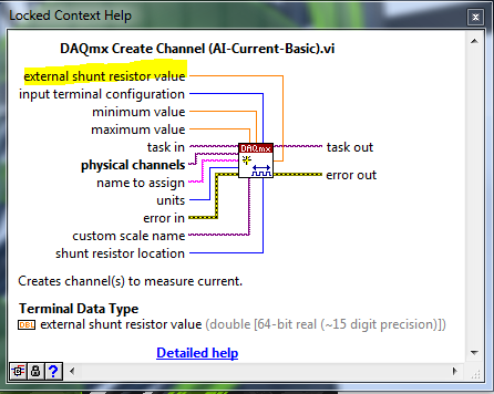
Do not use the DAQ assistant. You can use it to configure your task but then right-click on it and convert it to the DAQmx code.
The DAQmx create channel VI has an entry for the external shunt resistance value.
-
Read a resistance of the diode by vs NI USB multimeter
Hello
I read a resistance of the diode at some entrances to supply voltage
and I found that
to 0.2 V
the value of resistance by NI USB-6212: 200 ohms
the value of resistance of meter: 2 kohm
0.5 v
the value of resistance by NI USB-6212: 500 ohm
the value of resistance of the multimeter: 5 kohm.
Could you please let me know why the values are different by 10 times?
Thank you.
No - we can't measure the resistance in this way.
To measure resistance, you normally spend a current known and then measure the voltage. A DMM will be repeated by generating a little known current and measuring the internal tension. If you provide an external voltage thus, DMM internal resistance measurement will not work.
For the LabVIEW - The USB-6212 can measure the tension. If you want to measure resistance, while the unit is plugged, you need to know/measure current (for example through a shunt resistance) and the tension and then do R = V / I for the resistance. I don't know what the argument of type 6212 if you try to perform a measure of 'resistance', as it is not a source of internal current.
Oh, I thought that this all seemed familiar - here's a similar thread: https://forums.ni.com/t5/LabVIEW/daqmx-resistance-measurement-6251/td-p/3267084
-
Shunt calibration factors expected
I'm trying to shunt calibrate a rectangular rosette extensometer attached to a module CSC-SG01 (using a SCC-SG11). I use a SC-2345 connected to a laptop with a card DAQCard-6036E. I read in an analog voltage with the SG11 engaged and subtracting the value w/o it committed. The expected value of Vexpected = (R3 * Vex *(Rshunt+R4)) / (*(Rshunt+R4), R4 + Rshunt + R3) is then divided by the difference to get the correction factor. For the Vprevu, R3 = correct R4? I get a value of less than 1 correction factor (~. 97), which for me has no meaning, as shunt calibration is supposed to correct for the resistance of the wire. I understand that although the correction factor must be > 1?
Thanks in advance for your help
Hi William,.
If we look at what happens internally in the SCC-SG11 in looking pg 17-18 in the Manual, it shows a diagram and an equation for the sample. Set all values of 120 to calculate your measure expected and then it varies from 119 to 121 and divide by the expected value. If the resistance is greater than 120, you will get a lower measured voltage and a ratio of > 1. If the resistance is less than 120, you will get a higher voltage that is measured and a ratio of<>
-
Access 9236 shunt cal with scanning mode?
How allow us calibration shunt with scanning on the module 9236 quarter bridge strain gasoline
We are very happy with the release of Labview 2009 and RIO 3.2 because most of the cRIO modules now supported the scan mode.
We want to use the interface in scan mode with the quarter bridge strain Guage 9236 module, but we must be able to access the features of Shunt calibration. With the FPGA interface, you acquire a set of data. Then allow you the shunt calibration and gain a second set of data. Then you compare the two to get to a scalar value using some equations. This eliminates lead resistance in your calculations, which can be less than ignorable in certain circumstances.
Thank you
It was easy. I just hung out and left down the constant IO then right mouse clicked on it and all its I/O write properties come. Very cool. All too easy to be crio programming, lol.
-
"Bridge shun cal.vi" shunted the setting of the value?
I copied the "bridge shun cal.vi" LabView example "Acq gauges bridge samples (with calibration) .vi", to include in a strain measuring .vi I'm working.
My equipment consists of an SCXI-1001 chassis, modules of 1520 and 1314.
That means the acronym for setting the value of "Shunted"? Resistance value of triage (in ohms, I supouse)?
And it's less important to me, but think it may be interesting for others: how to choose between the calibration shunt resistance is or B?
Thank you
usuario
Hi user,.
You are right when you say 'shunt resistance' in VI stands "DAQmx perform Shunt calibration (bridge)" for the value of shunt in ohm resistance. As you can see on page 4 of the SCXI-1314 manual, the two shunt calibration resistors A and B are have a value of 100 kohm. In addition, page 4-28 the SCXI-1520 user manual specifies that they are are in style RN-55 (standard 1/4 W).
Choosing to respect so shunt calibration resistance A or B, the latter manual mentions on page 3-4 that "shunt calibration switches A and B are parameters of control of software that allow or activate or deactivate the shunt calibration resistors in order to form win calibration." In most cases, you do not explicitly switches shunt calibration check, he makes instead of software driver to automatically adjust them for you during the shunt calibration procedure automated. However, if you want to explicitly control the witches of calibration, you can write an application program which controls the shunt calibration switches.' and returns the user to Chapter 4, principle of operation, for more information.
I hope this helps.
Kind regards
-
Water-resistant IPhone 6s, hoax?
"I've heard many blogs of people who say things like ' finally Apple made a waterproof iphone water" and other things. It's about the iphone 6, not 7. It is a hoax, or is it true? They say things like resistant to water up to 1 ft.
Probably the hoax. Even if I have an iphone 6 I do not trust blog. but Apple, is it true or hoax?
Probably hoax xD
The 6s is not classified as resistant to water.
-
Did Apple Watch 2 (2016) resistant cabin sauna and hammam?
Did Apple Watch 2 (2016) resistant cabin sauna and hammam?
Hello
Read this article > water on Apple Watch - Apple Support resistance
Maybe you are looking for
-
Saved passwords are gone; just upgraded to Firefox 34.0.5
I've just (accidentally) updated for Firefox 34.0.5 for desktop PC, and now all my saved passwords are gone. I do not remove them. How? Why? What can I do to get back them? I am really annoyed at Mozilla to be always on my face to be upgraded, now th
-
Print files PDF FRO OS El Capitan
Why can I not print a PDF file after updating to OS El Capitan? I can print any other type of file except for a PDF file.
-
Update BIOS on Satellite Pro 2100
Hello I have a Satellite Pro 2100 (model #: PS210E-0053R-EN) and recently bought two 256 sticks of RAM for it, which according to the manufacturer, are compatible. They do not work, and I have I'll return them, but before the company was asked to tak
-
I have successfully configured the wireless device. When I attach flash storage to the iConnect drive, it appears in Windows Explorer under storage attached to the network and is accessible. However, when I try to join my backup drive Seagate more th
-
Inherit backup external hard drive history never asked?
After I set up my new iMac, I did a new migration between my old Macbook Pro and iMac. Migration process went perfectly, but when connecting my external hard drives with my Time machine backups I expected to see the option: "inherit the backup histor