reverse axis
Hello
I am trying to reverse the order of the y-axis of my 2D plot (do decrease).
I use Diadem 2012.
I see that in earlier versions, there was a selection "mirror...". ', but in Diadem 2012 I couldn't find it...
Any suggestions?
Kind regards
Hi, amel.
Ah, you're right. The 'Scaling Type' property is "DateTime" or "Inverted", not both. You can set it to "Inverted", but then you have to set the "Display Format" property of the string DateTime in data to "Numeric" portal so that the parameter "Inverted" stick. Your axis displays then the number of seconds since the AD instance up and down 0. To display time values date reversed, you must also create a UserCommand that uses the RTT() command and call it as an @ expression of function, passing it the variable CFV, format the y-axis numbers. I can help you to do, but it's not easy or obvious.
Still interested?
Brad Turpin
Tiara Product Support Engineer
National Instruments
Tags: NI Software
Similar Questions
-
How can I set digitally Board chart origin?
How can I numerically define the origin of the work plan? The answer closest I can find online advises do to drag the origin of drag? It's irritating because I think most people use Illustrator because of its accuracy. Why on earth would I just arbitrarily plop my artboard original any old where it's only the basis of my project as a whole. Anyone know how to change digitally?
Let me give you an example of what I mean. I need set the origin of the artboard to the x axis of a scatter chart. The label of this axis is centered vertically, so the work plan must actually extend on 3pts below the x axis. Not only that, but I would go back on the artboard so that when I traced my points, I can simply enter the number, rather than do a lot of math to get it in the correct position. I realize in Illustrator, there's a chhart tool, but it will not work for this project.
Right now, I have a work plan which is 144pt high, the x axis is at 137.19pt and the bottom of the label for the x axis is 144 ft. I need 0 to 137.19 and reverse axis, as well as a period is positive.

Check this thread
JS - change CS5 origin of the ruler from the bottom / left (as CS4)
-
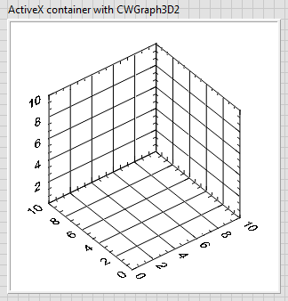
gone 3D reverse chart axis option
I want to programattically must reverse the axes X and Y of a plot 3D to answer the orientation of my installation. In older versions of labview, it was possible but now in 2013, this option seems to have disappeared. 2013 using a function called is mentioned "axis: range: range inverted", but he's not here.
He returned in a new update soon?
Kind regards
Martin
Hello Martin,
I'm glad that you were able to locate the property. The difference between the 2 garphs is that the 3-d chart of Surface (using) uses ActiveX and is supported only on Windows OS. The other chart (which I used) looks more like a native control of LabVIEW. The differences are detailed here.
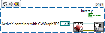
I don't know why the axis reversal property is not exposed, or if it will be in future versions, but here is a quick work around. Place a container ActiveX on your façade. Right-click on it and select Insert ActiveX object. In the dialog box that pops up select CWGraph3D control. This should give a similar 3D-graphics on your front, you're used to using.
On the block diagram, you will get a 3-d chart reference ActiveX. That you can use to manipulate the graph using 3D graph properties screws (range of functions > programming > graphics and sound > 3D graphical properties). To invert the axis, you can do something like this.
If you notice the data that you provide to draw remain same in your approach and this workaround.
I hope this helps.
Kind regards
Michel
-
Reversal of the y-axis on a Basler scA640-70gc using labview
I run a scA649-70gc Baslar to give me a stream live experiences running in another room, however the picture I get is upside down and flipping the camera physically is not an option. Does anyone know a way view laboratory could solve the problem?
Try using IMAQ symmetry in the palette of image Manipulation. He reverses the images and possibly turns them. Try the first three options and see what is happening in the image. I want the flip around the horizontal axis for vertical turning. If I remember correctly, flipping around the Center rotation 180 degrees so it's what you want.
If none of them only what you want, take a look at IMAQ turn. Who can turn an image of an arbitrary number of degrees, including 180. I think she's doing a more complicated manipulation, it would be much slower than the symmetry. If you need to, you could probably make a vertical and horizontal flip using symmetry faster than a rotation.
Bruce
-
Why my axis of tone curve is reversed
Can you help me? My axis of tone in PS curve seem to be reversed, so instead of black down left up to white in the upper left and lower right, mine is white down goes to the dark at the top of the vertical and the horizontal right. I googled for a response but no luck. Am I missing a flip button? How can I make normal? Thanks for your help.
I have dnuee and the axis of the curve are correct in LR.
This option is enabled?

Fenja
-
How to reverse the axis graduation
I am a beginner in adobe illustrator help, and I just need to know how to make the axis, say the category axis, in adobe illustrator from maximum to minimum...? How to make my own scaling?
Maha,
I'm afraid that leaders and axis are entirely immutable, at least in the way (I think) you mean.
In CS5, the y-axis was reversed and it is possible to unreverse it, but freely change the axis and leaders was never a real option. You can configure your own leaders as work and turn them into guides, but that would be only something added by you, not used by Illy.
-
How can I reverse the y-axis to have the lowest number at the top?
Hello, I do a study on the water level of the river and I need to invert the values of the y-axis. It is very easy to do with Microsoft Office Exel but I don't know how to do it with the number.
I have numbers 3.6.1
Hi I,.
I have some difficulty to visualize data and graph is to create. In my mind, data points are projected on the chart to indicate an increase in the level of the surface of the River (or debit) level.
Perhaps an example of data would be clearer demand.
Kind regards
Barry
-
is there a way to reverse the axis Y in illustrators CC?
I'm working on a project that can be plotted on a grid and I wonder if its possible to invert the Y axis that are positive numbers and negatives are falling.
qwotis,
If the link of Doug fails to do so, you can change (I hope) manually the parameters relevant of preference as follows:
0) close down Illy (you can change the closed preferences with Illy file);
(1) find and open the AIPrefs (Win talk) or Adobe Illustrator Prefs (Mac talk) file with a text editor such as Notepad or TextEdit. the preferences file is a (hidden) file in the folder (hidden) parameters of Adobe Illustrator CS5
(2): find and replace the following two bits of code:
/isRulerOriginTopLeft 1 > /isRulerOriginTopLeft 0 (replace the 1 with a 0)
/isRulerIn4thQuad 1 > /isRulerIn4thQuad 0 (replace the 1 with a 0)
This is a global change, so you no longer have to do it once (just like you can cancel it once).
You can find file preferences here:
https://helpx.Adobe.com/Illustrator/KB/preference-file-location-Illustrator.html
-
Vertical axis is reversed in CS5?
When I want to move an object to the top I put a negative number? What is a preference that I'm dominant?
Chris,
There is still hope, at least for the "BOLD":
You can:
(1) find and open AIPrefs (Win talk) or Adobe Illustrator Préfs (Mac talk) of the file. It is a hidden file in the folder hidden settings of Adobe Illustrator CS5
(2): find and replace the following two bits of code:
/isRulerOriginTopLeft 1 > /isRulerOriginTopLeft 0 (replace the 1 with a 0)
/isRulerIn4thQuad 1 > /isRulerIn4thQuad 0 (replace the 1 with a 0)
-
2-axis... 1 switch House? Find reference
I use a card of e/s NOR-7330 movement, to which it is a Council of I/O UMI 7764 motion. This card is used for the stepper motors closed loop. Currently, I am trying to write a VI that, for each axis, turn each screw lead until running personalties on the screw in the switch to home and once they make the position can be reset to a value of knowledge, basically reseting this House switch in a position of reference / reference. The goal is to get away with just using 1 switch House, for 2 axes, is it still possible? Is it safe to do, or help would be rear limits and a House move work better?
I ran the find reference VI with little luck. This will simply an axis until it hits the home button, but immediately running the engine in reverse. What I read I suppose it's considered the race before or back, instead of a switch at home? IM assuming that something in my MAX settings is incorrect, and I was hoping that someone with more knowledge would be useful. It would be great if I could run 1 axis to the switch House assign to a relative position of the switch House, then do the same for axis 2.
Thank you
Almost any Max setting may be overriddin in LabVIEW. You have a lag move together, that's why your axis moves after finding the switch house edge. I disable the switch House to the MAX and then use Smart turn in reference to find parameters. Do not have one a motion compensation or reset in MAX position. Use the reference find VI, then when that VI is complete, you can make a move of compensation and/or reset the position using LabVIEW.
-
Intensity plot zoom is back with reverse YAxis.
In order to make my data intensity ground pull from top down, I reversed the x-axis using the YAxis.Inverted property. It worked perfectly. However, when you try to zoom the field of intensity, the zoom function is not reversed. In other words, if you zoom in on the top of the chart, it actually zooms in from the bottom. Is it possible to fix this?
Thank you
Jon
Hello Jon-
Unfortunately, it is a known problem (id 290072). I think the only way you can really work around this issue is to remember the axis range before that happens the zoom, and then assign a new scope object to the axis which corrects the incorrect zoom by handling the Zoom event. I have attached a source for a quick fix, that I just wrote - perhaps you will find it useful.
This problem will be fixed in the next version of service pack, which will be later this summer.
I'm sorry for the inconvenience-
NickB
National Instruments
-
Hello! ...
I have developed a program that has the algorith as follows:
1 x steps and Y steps determne table of pixel size I want.
2. for each Y increment the X scan by a fixed number of steps, then there
3 step 2 is repeated until there is reached its MAX State.
Problem:
After the scan X say 10 steps I want to reverse and go back to the original, and then again after Y increments X scan and return to original.
Its a RASTER scan basically.
I'm not able to understand why and how to add a part to get the engine back to its original position.
Please find the VI and tell me my mistakes.
Thank you
Hello
You have two nested while loops: one that moves in the direction y and one inside that moves in the x direction. There are two ways you can implement replacing the x-axis zero.
1. the stop direction x loop condition is once he traveled to the stop. You can add that a deal right behind what just loop said the engine back to zero.
2. in management's loop before the axis x running tell the x axis to return to zero. This would lead to zero each time before axis x begins his move.
Both ways will accomplish the same thing but got it back after the move and two the fact before.
Kind regards
Greg H.
-
I have a circular bearing that I use the eraser of the appropriate size brush to remove the background for the part of the axis of rotation. I then want to choose a larger size of Eraser brush to cover all turnover and save it and remove anything that is not covered by the brush. Y at - it a command which reverses the Eraser brush function? Thank you. Dave
You can make a selection with one of the selection tools (and reverse if necessary) to choose what to erase with the Eraser tool.
-
How focus a JavaFX Group properly and set the pivot (reverse) by using translations in 3D space?
Description:
I m referring to the Oracle tutorial http://docs.Oracle.com/JavaFX/2/transformations/jfxpub-transformations.htm using the transformations.zip source code, which is available for download on this page. I Don t understand why they Center the xylophone in space 3D like this and why they calculate the pivot (reverse) using translations. So they are creating a large number of groups, including rectangles, representing the xylophone, in addition to finally to a group called "cam".
class Cam extends Group {
     Translate t  = new Translate();
     Translate p  = new Translate();
     Translate ip = new Translate();
     Rotate rx = new Rotate();
     { rx.setAxis(Rotate.X_AXIS); }
     Rotate ry = new Rotate();
     { ry.setAxis(Rotate.Y_AXIS); }
     Rotate rz = new Rotate();
     { rz.setAxis(Rotate.Z_AXIS); }
     Scale s = new Scale();
     public Cam() {
          super(); getTransforms().addAll(t, p, rx, rz, ry, s, ip);
     }
}

final Cam camOffset = new Cam();
final Cam cam = new Cam();
...
camOffset.getChildren().add(cam);
...
final Scene scene = new Scene(camOffset, 800, 600, true);
...
The Group "cam" is added to another group called "camOffset", which is added to the 'scene' as root the node.
Until there , everything is understandable to me, but there is a method, called "frameCam (.)" which calls 4 other methods: ""
public void setCamOffset(final Cam camOffset, final Scene scene) {
     double width = scene.getWidth();
     double height = scene.getHeight();
     camOffset.t.setX(width/2.0);
     camOffset.t.setY(height/2.0);
}

//=========================================================================
// setCamScale
//=========================================================================

public void setCamScale(final Cam cam, final Scene scene) {
     final Bounds bounds = cam.getBoundsInLocal();
     final double pivotX = bounds.getMinX() + bounds.getWidth()/2;
     final double pivotY = bounds.getMinY() + bounds.getHeight()/2;
     final double pivotZ = bounds.getMinZ() + bounds.getDepth()/2;
     double width = scene.getWidth();
     double height = scene.getHeight();
     double scaleFactor = 1.0;
     double scaleFactorY = 1.0;
     double scaleFactorX = 1.0;
if (bounds.getWidth() > 0.0001) {
     scaleFactorX = width / bounds.getWidth(); // / 2.0;
}
if (bounds.getHeight() > 0.0001) {
     scaleFactorY = height / bounds.getHeight(); //  / 1.5;
}
if (scaleFactorX > scaleFactorY) {
     scaleFactor = scaleFactorY;
} else {
     scaleFactor = scaleFactorX;
}
     cam.s.setX(scaleFactor);
     cam.s.setY(scaleFactor);
     cam.s.setZ(scaleFactor);
}

//=========================================================================
// setCamPivot
//=========================================================================

public void setCamPivot(final Cam cam) {
     final Bounds bounds = cam.getBoundsInLocal();
     final double pivotX = bounds.getMinX() + bounds.getWidth()/2;
     final double pivotY = bounds.getMinY() + bounds.getHeight()/2;
    final double pivotZ = bounds.getMinZ() + bounds.getDepth()/2;

//*1*
     cam.p.setX(pivotX);
     cam.p.setY(pivotY);
     cam.p.setZ(pivotZ);
//*1*

//*2*
     cam.ip.setX(-pivotX);
     cam.ip.setY(-pivotY);
     cam.ip.setZ(-pivotZ);
//*2*     }

//=========================================================================
// setCamTranslate
//=========================================================================

public void setCamTranslate(final Cam cam) {
     final Bounds bounds = cam.getBoundsInLocal();
     final double pivotX = bounds.getMinX() + bounds.getWidth()/2;
     final double pivotY = bounds.getMinY() + bounds.getHeight()/2;
     cam.t.setX(-pivotX);
     cam.t.setY(-pivotY);
}
If the method ' setCamScale (...) 'is understandable,' setCamOffset (...) ' puts the root node ('camOffset') in the center of the screen, but I Don t understand the 2 following methods at all. Of course, the child ("cam") is not centered, by putting just the root node ('camOffset') in the center of the screen, but how they focus the xylophone / "cam" and set the pivot, using translations:
Questions:
- Why they use 3 different translations (', 'ip', 'p')?
- Referring to ' setCamPivot (...) ': Why they are the first translation of 'cam.p' to "pivotX", 'pivotY' and 'pivotZ' and then 'cam.ip' to '-pivotX', '-pivotY' and '-pivotZ' (marked in the source code with * 1 * and * 2 *)? Should he not just put the Group at his position, where it has been positioned before, as if the method has never been called? That would be my guess, because I expect that an object is placed in the same position as before, if I first move with the values X, Y, Z and then return with the same values - X, - Y, - Z in the opposite direction.
- Even with the method ' setCamTranslate (...) ' ': Why use another translation "cam.t", moving the Group ("cam") with the same values "-pivotX', '-pivotY' (and not '-pivotZ'), which they used in the"setCamPivot (...) method `?
Annotations:
Of course it works, the xylophone is located in the center of the screen and could turn perfectly, without change of rotation point / pivot point, but I Don t understand how they did it. I read everything about layoutBound, boundsInLocal, boundsInParent, blogs about page layout and page layout goes into javaFX https://blogs.oracle.com/jfxprg/entry/the_peculiarities_of_javafx_layout and http://amyfowlersblog.wordpress.com/2011/06/02/javafx2-0-layout-a-class-tour/ and finally a large number of questions to stackoverflow, but I still Don t understand the meaning behind the methods stated.
Before the call of ' frameCam (...) ', they ask:
double halfSceneWidth = 375;  // scene.getWidth()/2.0;
double halfSceneHeight = 275;  // scene.getHeight()/2.0;
cam.p.setX(halfSceneWidth);
cam.ip.setX(-halfSceneWidth);
cam.p.setY(halfSceneHeight);
cam.ip.setY(-halfSceneHeight);
I deleted these lines, because it doesn't change anything.
The base in place, is that there are three defined different rotations, one around each axis. Of course, these could be combined into a single rotation, but doing so would make the geometry in the mouse dragging very complex managers. As it is, the degree of rotation around each axis can be calculated and changed independently.
In general, the rotations are defined by an angle, an axis and a (pivot) point. The axis is a 3D vector and goes through the pivot point; the rotation is around this axis through that point.
In the configuration in the example, the pivot of each of the individual rotations is set to the default (0,0,0). Because we really want the rotation to be around the center of the group, not the original, the Group translates first point appropriate pivot (ip), the rotations are applied then (around (0,0,0) after translation by ip), then the group is reflected in its location of origin (p). These operations are not commutative, yes show ip, then the rotation, then p is not the same as when you run ip, then p, then the rotation (in the second, ip and p would cancel and rotation would be about (0,0,0) instead of around the Center).
For good measure, there is a scale, that is also applied after ip (so that scaling occurs from the Center, not the original) and then a final translation.
The final effect is that there is a lot of transformations that can be controlled independently. There is a scale (s), a rotation about each axis (rx, ry, rz), and a translation (t). The p in translations and its inverse ip are just "housekeeping" to ensure that rotation and scaling are done from the center of the screen, instead of (0,0,0).
So:
Why they use 3 different translations (', 'ip', 'p')?
p and ip are translations for the rotation and scaling are done from the Center and not to the origin. t is a general translation, the user sees.
Referring to ' setCamPivot (...) ': Why they are the first translation of 'cam.p' to "pivotX", 'pivotY' and 'pivotZ' and then 'cam.ip' to '-pivotX', '-pivotY' and '-pivotZ' (marked in the source code with * 1 * and * 2 *)? Should he not just put the Group at his position, where it has been positioned before, as if the method has never been called?
He puts the group to its original position, but other changes are between p and ip. These transformations behave differently (in a planned way) because the group is translated when they are applied.
Even with the method ' setCamTranslate (...) ' ': Why use another translation "cam.t", moving the Group ("cam") with the same values "-pivotX', '-pivotY' (and not '-pivotZ'), which they used in the"setCamPivot (...) method `?
The t values are changed in the mouse Manager (with alt-middle mouse button-drag, which I can't test actually using my trackpad...). As you have noted, the effect of p and IP translation cancel out, so we end up with t, which can be changed by the user. They could have combined t and p a single transformation, but updated since the mouse Manager would have been more delicate, and the intent of the code would be less clear.
-
Spotlight, apparent and reverse
I have a spot of light that is key to move, axes XYZ and touch-ups to pointofinterest, around 3 axis again.
I want to another place for 'point of interest' relatives and X, Y, z order (I separated them), but not all reverse. I guess that the expressions are the way to go, but I have very little knowledge of what they are capable.
If you imagine a physical spotlight, I essentially want to stick another to the back of it and direct it in the other direction, regardless of where the original Spotlight goes.
I have not found someone online who did this, but if there are resources or plugins that could help me, please point me in the right direction.
I have a few questioins myself.
You say you want another place to the center of interest of the parents but everything reversed. It makes no sense to me. The point of interest is where the place is indicated and not having opposite No. There is a line between the position of the projector and the point of interest. That's the way you would with an expression, but there is a much easier way.
Here are the steps. Create 1 spot. Set the point of interest on the center of the model for X and there then the Z value something like 500. Set the X position and Y of point 1 in the center of the model and Z to 0. What you want to do is to finish with the values X and Y position and the point of interest to be the same and the Z value offset to a reasonable distance.
Now duplicate 1 spot, add a null 3D. Copy the value of position for spot 1 to null. Spot 1 parents to null. Rotate 180º null in y. Parent spot 2 to null. Animate the value null.


Maybe you are looking for
-
When I visit a site, firefox reports invalid security certificate, but does not add an exception
When I visit a site that has an invalid security certificate, my mobile me has a nice little dialog box telling me that the connection is not reliable and allowing me to view the site by clicking on ""I understand the risks"my office however shows a
-
New macbook pro got adware in the first instant - how to delete this?
I bought a Macbook pro yesterday, just started the machine. Open one of my site in safari and found that see no adsense ads. later, I found that a few other ads are in place and place adsense ads. How is it possible in a new machine in the first inst
-
Upgrading RAM on satellite L20-217
Hi guys,. I have a satellite L20-217 and I'm looking to upgrade my ram 256 to 2 GB (or at least 1 GB). I did some research but I am still confused about this module (s) to buy and how to install it. I'm new on this and I will be very grateful if anyo
-
Windows Installer keeps trying to install Vongo on Windows XP
When I bought my laptop a few years ago, Vongo came as one of the pre-installed services. I removed it, but when the other connection of users with their own username, windowns Installer keeps trying to install it, which is very annoying because you
-
Fault of updated for Powerpoint 2007
I have a question where Windows update guard trying to install an update for Powerpoint 2007 and failing. It is a failure because the app no longer exists. I think it was just bad timing that the update came through right all the time, that the app h