RFSG - generate Modulation DTMF
PXI: 5670 RF Vector Signal Generator 2.7 GHz (5621 ARB and 5610 Upconverter)
5421 ARB
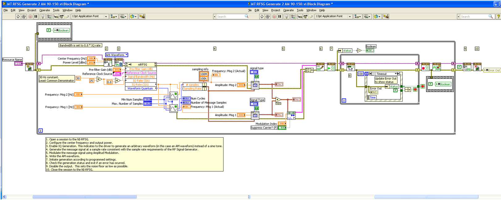
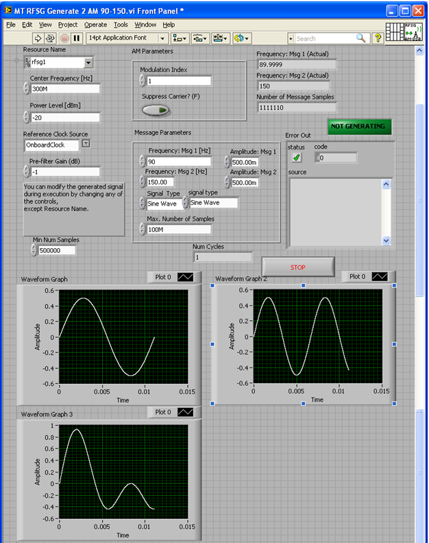
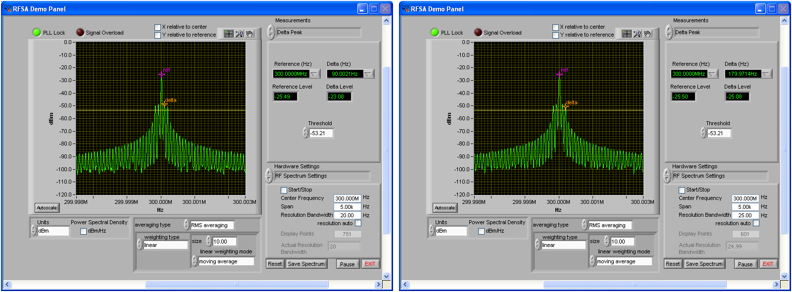
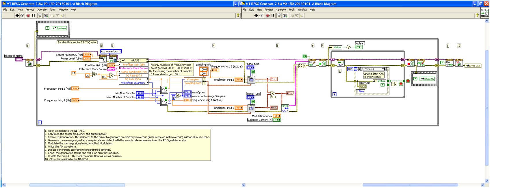
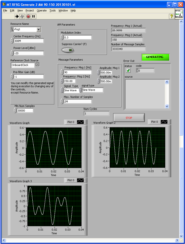
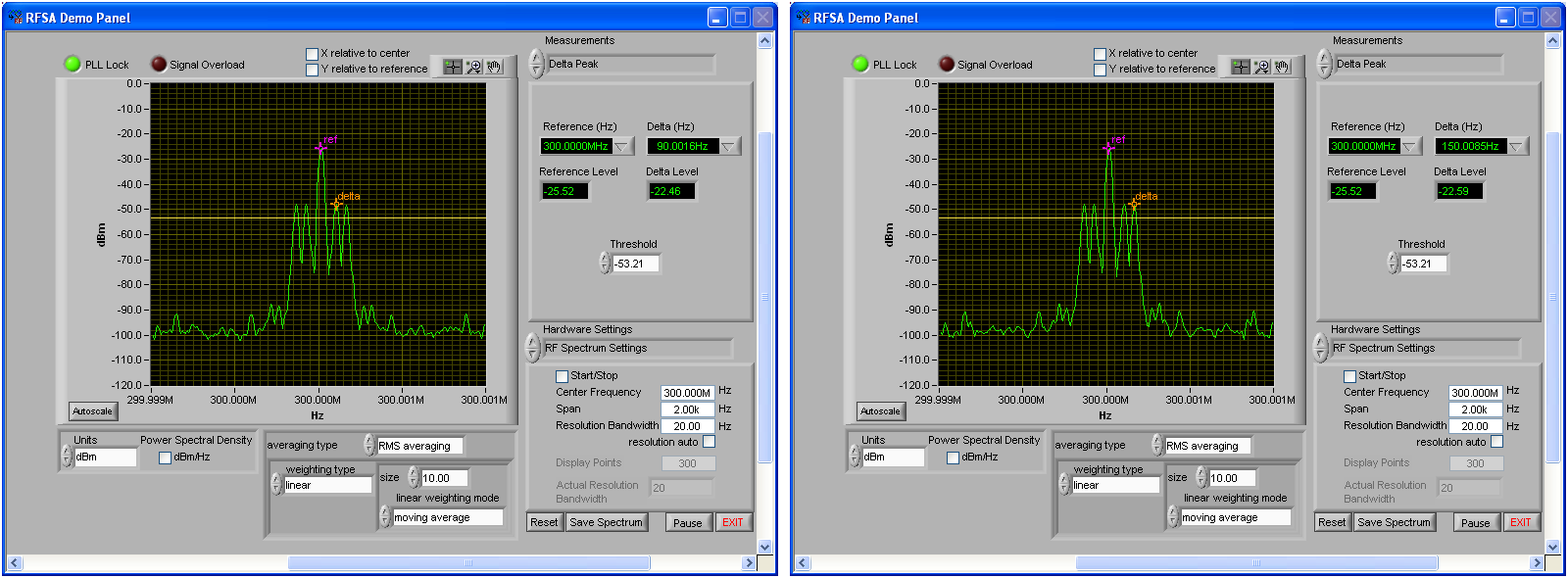
My goal is to generate a modulated signal - dual-tone with 90 Hz and 150 Hz carrier modulation of 300 MHz. It was built with examples of how to include the two tones, but I couldn't get the second tone at frequency, I said to (it was only a multiple of the first images of frequency - see). By increasing the number of samples by 3 before generating the sinusoids, I think I managed to do work, but I can't explain why I was getting so many Spurs, or why "compel him frequencies and Subvi samples' (a right after the node property) does not take care of it. Why should I this hard-coding? Will this work? Any information would be great!
Hello regulator,
In my view, that it is a sampling problem. You take the number of samples in the 90 Hz signal rather than the 150 Hz signal. 150 Hz signal need more samples to represent accurately, so this number of samples increased from 90 Hz is not enough. When you multiply the number of samples by 3, you simply oversampling. It will be a little more taxing when you do the modulation, but it's okay as long as your machine takes care of everything.
Concerning
Tags: NI Products
Similar Questions
-
RFSG - generate Dual Tone Modulation with narrow frequency
Junk
This message has been a supplement... refer to RFSG - generate Dual Tone Modulation for correct display
-
How can I generate modulated amplitude signal?
How can I generate modulated amplitude signal?
I got this VI examples NOR but in this VI "m message signal .vi is missing. So, how can I generate missing VI or VI full for the Amplitude modulation signal using 5441 PXI and PXI-5610 as upconvertor. If possible guide me steps to generate.
Thank you and best regards
Isabelle Kodgirwar
Graduate student
University of Texas at Arlington.
Hi Aron,
-
How is the SHA hash for a generated module?
Hello
I was wondering if someone had more information about the CodeModuleManager.getModuleHash () method? The API says:
"Returns the algorithm SHA hash in a module."
I've used it before and it gives me what looks like a SHA1 hash. The only problem is, I'm not able to reproduce this hash by generating a SHA or SHA1 hash using my computer.
For example:
If the BlackBerry gives me 02A826682116ED6A7B9B4429CAAFD2DF198A29F7 for the net_rim_app_manager module, running the same .cod file does not provide me with a corresponding number:
azazel:tmp sheran$ openssl sha net_rim_app_manager.cod SHA(net_rim_app_manager.cod)= 03804aa899166d0eed95ddf3a758446c2159ee4b

azazel:tmp sheran$ openssl sha1 net_rim_app_manager.cod SHA1(net_rim_app_manager.cod)= 7feebefdad9a39d98c70d0282cca935fd2dc55fe
My questions:
1. How did this hash generated for a specific module?
2. how the calculation would be different for a module with many brothers and sisters?
Thank you
Sheran
The tail of each signed module is a list of signatures. When you calculate the SHA-1 hash, you must exclude this part of the binary file to hash.
When a module is composed of several modules, it is in fact a ZIP file. Each ZIP entry that contains a module (brother) has its own hash and signatures. Easiest way to test this is to decompress the. COD file and calculate the values of the hash for each file.
-
With the help of the external RF signal generator
Hello.
I just want to ask how can I remove the frequency shift if I use an external RF signal generator (instead of the RF PXI-5652 signal generator module). I understand that in the case using the OR to generate RF signals, frequency shift is deleted by setting the same source of reference for the transmitter and the receiver clock (placing the clock source of reference to PXI_CLK of the façade of generation VI and VI of the acquisition).
Thank you very much.
Hi Betty,.
In this case, no changes are needed, such as modules OR still use background clock basket PXI as the ref. clock source If you are still having a frequency shift, you probably need to configure sig gen to lock a clock external REF. Usually, just make the connection of the signal is not enough - you must also indicate the sig gen to use the signal connected to the input clock ref. Terminal
If you use the sig gen as clock source master Réf, connecting the 10 MHz of the gen of GIS at the BNC 10 MHz IN on the back of the PXI chassis replaces the clock native from the newly connected with the PXI chassis backplane, and analyzers are still using the clock background basket PXI as the source clock Ref (no change to the SW settings).
Kind regards
Andy Hinde
RF systems engineer
National Instruments
-
Coded frequencies-16 generator control switch
I feel really lame to ask this, but I can't understand how to connect a code switch to select 16 different frequencies in the generator module. I keep trying to figure out how with a switch output and a generator of output that I can control the generator of the switch. I can't imagine how the goes - inta and outta goes to get wired.
I keep thinking, I saw one such example, but can't find it

CJ, the example was everything I needed to make things work properly. It was logical that the output voltage of the coded switch would control the signal generator which he does very well.
Thank you very much!!!
-
TestStand - dynamically retrieve a prototype of code module
Hi all
Thank you for reading me

I am currently trying to find little code (if it exists), or some ideas/directions to automatically retrieve a prototype of code module.
This code can be written in any language (LabVIEW, C, TestStand, or other)
My final goal is to scan a directory for screws, dll (and so on) and get their prototype in order to have an external database generator module filled code.
Where there is no such thing as this code, could you please let me know what methods I could interact with the TS engine to retrieve a code module.
Best regards.
Hello
This c# example you will see what needs to be done to get the list of parameters
SequenceCallModule objModule is step (SequenceCallModule). Module; Just a note: only if you're sure it's a SeqenceCall
objModule.UseCurrentFile = true;
objModule.SequenceName = strSeqName;
objModule.UseSequenceParameterPrototype = false;
objModule.LoadParametersFromSequence (sequence); Parameters SequenceCallParameters = objModule.Parameters;Concerning
Jürgen
-
Module Template edits do not appear
I create a dynamic menu in a "bootstrap" eastwindinsurance.com site
I'm down the module in the structure of the Boot Menu that looks like this:
< nav class = "navbar, navbar-fixed-top" >
< div class = "navigation bar inner" >
"< div class = 'container' > < a class ="btn, btn-navbar"data-toggle = 'collapse' data-target = '.nav-collapse' > < span class = 'bar icons' > < / span > < span class = 'bar icons' > < / span > < span class = 'bar icons' > < / span > < /a > < a class = 'brand' href ="... / index.htm "> FIexAssist < /a >"
< div class = "nav-collapse" >
< ul class = "nav" >
< class li = "active" > < a href = "/ flexassist.htm" > home < /a > < /li >
< li > < a href = "/ benefits.htm" > benefits < /a > < /li > ""
< li > < a href = "/ assistance.htm" > support life < /a > < /li > ""
< li > < a href = "/ claims.htm" > claims < /a > < /li > ""
"< li > < a href ="... / premiums.htm "> premium < /a > < /li >"
"< li > < a href ="... / faq.htm "> FAQS < /a > < /li >"
< /ul >
< / div >
<!-/-> .nav-collapse
< / div >
< / div >
< / nav >
And I've put it in like this:
< nav class = "navbar, navbar-fixed-top" >
< div class = "navigation bar inner" >
"< div class = 'container' > < a class ="btn, btn-navbar"data-toggle = 'collapse' data-target = '.nav-collapse' > < span class = 'bar icons' > < / span > < span class = 'bar icons' > < / span > < span class = 'bar icons' > < / span > < /a > < a class = 'brand' href ="... / index.htm "> FIexAssist < /a >"
{module_menu, 564015}
<!-/-> .nav-collapse
< / div >
< / div >
< / nav >
Because the generated Module Code looks like this:
< div id = "cat_1118133_divs" >
< ul id = "nav_1118133" >
< li > < a href = "/ one.html" > point a < /a > < /li > ""
< li > < a href = "/ two.html" > point two < /a > < /li > ""
< li > < a href = "/ three.html" > point three < /a > < /li > ""
< /ul >
< / div >
I gave you the div a class ' nav - collapse " and the ul one class of 'nav' in the container and patterns of Group respectively menus.
The problem is that for some reason any changes made to the model code are not passed. I just get the default template by the way.
That is what it is?
Thank you
Cam
Hey Cam, do you mean you use the layouts of the menu module? If so you must use the tag v2 module code, it's just the default module label, you have there.
-
Hi all
I'm doing EVM measurement signal (modulated using 16QAM) OFDM using VST SMU-5645R.
But I get 0 and one EVM constellation evil.
I am not able to solve the problem. Can someone help me please? I have attached the image of the part of demodulation of the code with this message.
Thank you
Anupama
Thanks, Anupama. The new link works.
Your EVM measurement occurs only on the data passed out of your loop to demod. I noticed that you have no output condition on this loop, with the exception of a mistake. In this case, the data passes out will be empty (the only mistake might be a time-out of the dequeue item or symbols calling card MT). I don't know how the loop could out at all because there was no time limit set on the primitive dequeue item.
Second, remember your last post you must set samples by the symbol of an even number.
"With the samples per symbol being two, beginning for the input stream being relaxing ' Output Stream Start Trigger", and the reading block size 16000, I was able to get the data. Oh, I plugged in also the loop demod to leave first data table size is greater than 0; otherwise, the extent of EVM is never executed. Do you want the EVM measurement in your loop demod? Note that the data was not very good. I don't know exactly why, but would it be a problem with your calculations demod? Is there a reason that you do not use the MT demod VI?
With all that said, what you're trying to do with this project? If you try to measure EVM to a QAM signal, have you tried running the "MT RFSG generate QAM' and"MT niRFSA QAM Demod"example screws at the same time? You try to make a few additional calculations?
-
DASYLab how to write data to a file every 15 minutes
Hi all
I use dasylab and datashuttle/3000 to record data. What I want to do is to write data to a file every 15 minutes. I use the milti-file, which can write data to the file diffenret, but how do I control the timing, as the journal data every 15 minutes automatically.
The other problem is that I use FFT analysis of the frequency spectrum. How can I determine the value of frequency where the peaks that happens.
Thank you
Write less data in the file that you have collected requires the reduction of certain data.
There are three techniques to consider.
With an average or an average of block - both reduce the data by using a function of averaging, defined in the module. To accomplish the reduction of data, choose block or RHM mode in the dialog box properties, and then enter the number of samples/data values that you want to reach on average.
Average - when you reduce the data, you also should reblock data using the block length of the change in the output parameter. For example if you enjoy at 100 samples/second with a block size of 64, the average module configured on average, more than 10 samples will take 10 times longer to fill a block. The initial block represent 0.64 seconds, the output block represent 6.4 seconds at a sampling rate of 10 samples/second. If you change the size of output in one block, the program remains sensitive.
Average block - average values in a block against each subsequent block, where the average is based position. The first samples are averaged, all second samples are average... etc. The output is a block of data, where each position has been averaged over the previous blocks. This is how you will be an average data FFT or histogram, for example, because the x-axis has been transformed in Hz or bins.
Second technique - separate module. This allows to reduce the data and the effective sampling rate jumping blocks or samples. For example, to reduce the data in 1000 samples / second to 100 samples per second, configure the module to keep a sample, jumping 9, keep one, jumping 9, etc. If you configure to skip blocks, you will not reduce the sampling frequency, but will reduce the overall amount of data in a single block 9, for example. It is appropriate for the FFT data or histogram, for example, to have the context of the correct data.
Finally, you can use a relay and a synchronization module module to control. For example, to reduce a sample data every 15 seconds, configure a generator module of TTL pulses for a cycle of 15 seconds of time. Connect it to a Combi trigger module and configure it to trigger on rising and stop the outbreak directly, with a trigger value after 1. The trigger output connects to the X of the relay command input.
In addition to these techniques, you can change the third technique to allow a variable duration using a combination of other modules.
Many of these techniques are covered in the help-tutorial-Quickstart, as the data reduction is one of the most frequently asked questions.
In regards to the FFT... use the module of statistical values in order to obtain the Maximum and the Max Position. The Position of Max will be the value of the frequency associated with the Maximum value. The output of the statistics module is a single sample per block. Look at the different FFT sample installed in the worksheet calculation/examples folder.
-
niRFSG Initialize.vi error: AWG resource name is not valid
Hello
I use an SMU-5442 arbitrary signal generator and a PXI RF Upconverter - 5610. The RF PXI-5610 converter is PXI1Slot5 inside the MAX and the SMU-5442 AWG is PXI1Slot7.
When I gohttp://ftp.ni.com/pub/devzone/epd/rfsg-generate-fm.vi of http://zone.ni.com/devzone/cda/epd/p/id/5620 , I get the error messages.
For the resource name = PXI1Slot5
code-1074117675
niRFSG Initialize.vi a session cannot be created because the resource AWG name is not valid. Specifty the resource name of AWG Max by right clicking on the converter, and then select Properties. If you specify the working group through the chain of the Option, make sure that the resource name of AWG is valid.
For the resource name = PXI1Slot7
code-1074117636
niRFSG Initialize.vi the specified device is not supported by this driver.
which is correct, because PXI1Slot7 is the GTA and the VI is just using the niRFSG screws
When I use a selector instead of the string of the Option, I can only choose the RF PXI - 5610 Upconverter is PXI1Slot5, but I still get the same error message.
A you link them in MAX? In other words, the converter and the working group.
-
output signals of the rectangle a PEAK sine wave conversion
Hello
I have a question on the treatment of a PIC16F84 output signals. It seems that the simulation of Multisim does not work properly - but before I blame Multisim, I ask the community NOR or software engineers or a solution. Because I'm German, you are invited to continue this thread in German if it is allowed by the rules of the forum. If you need additional information to analyze my problem, I'll be happy to provide.
The circuit itself has to convert "composition by pulse" signals "tone" (DTMF tones). So you can get old, classic phones work on new devices that do not support the "composition of pulse" more.
The circuit is powered by the analog telephone line current loop line. The PIC is provided by a rudimentary voltage regulation and count pulse signals (voltage failures / power interruption on the telephone line). After that the captain means the series of impulses in their equal number (e.g. 3 pulses = number 3). The captain gives finally two signals with different frequencies to generate a DTMF tone (e.g. number 3 here is 697 and 1477Hz). As you can see in my PDF file attached, it works very well.
Now I have to convert the rectangle wave given by the captain to an at least similar to a sine wave form - otherwise the device that receives the DTMF tones won't understand them.
So I connected a low-pass filter at the output of the PIC. Now, expect the rectangle signal to be smooth in a way as the 'e-function' will (loading / discharging a capacitor through a resistor). But the results are very far from that - as you can see I have very strange curves.
When I implemented a frequency generator with the same output signal as the PEAK and the low pass filter even I get curves as expected.
So we can say that the output of the PIC works like a frequency generator in my circuit. But why does the filter not behave as it should?
I've tried a lot of different values for the parameters of my RC-filter and simulation - this does not solve the problem.
It would be nice if someone has any idea how to solve this problem.
Thank you.
The output impedance of the PEAK may be too high. May be that my car 50 output? Try scaling of impedance of the filter. Do the 10000 ohms resistance and capacitor 10 nF.
Lynn
-
Save all the data for a while loop
I already asked a similar question, but it is perhaps not very clear, and there are a few concepts that I did not understand.
1. I have a keyboard to generate flow DTMF signal (I call it stream because it contains several shades that consist of a full phone number)
2. I would like to save it as a wav file, but I guess that another format is correct and because the writing on a wav file does not support add so for this particular case, I use writing waving instead of writing to wav format
My approach is to have a structure of queue so that I can write each iteration results in a file.
(i) when I try to retrieve the data, there's nothing but 0.
(II) my intention is to get 8000 samples per second (fs = 8 000) but he back up data so fast
I have attached the file so if there is a way to solve problems, please help me.
This vi includes many elements discussed above. There are no provisions for the intervals 'no signal '.
Changes: Replaced with native features of LabVIEW Mathscript node. Mechanical Action to latch release button. Cluster to array replaces Unbundle and table to build. Reshape the table to match the shape of the keyboard. Separate searches for frequencies of line and column. Note that this is easily extensible to handle the 4 x 4 keyboard. Structure of the event added. Added the stop command (but not implemented stop to the loop of the file). Added indicators for diagnostic purposes. Added FFT spectrum and graphic.
I disabled writing to part of the file for testing.
Lynn
-
Impossible to compile the FPGA in project
Hello
I get the following error when I am trying to compile an FPGA VI on a Compact Rio 9022, I missing something on my stand in?
Everyone has seen this before and know what is happening?
An internal software error occurred. Please contact National Instruments technical support on ni.com/support with the following information:
7 error error component the generator module VI: NULL
Possible reasons:
LabVIEW: File not found. The file may have been moved or deleted, or the path to the file would be incorrectly formatted for the operating system. For example, use- as Windows path separators: on Mac OS, and Linux. Check that the path is correct using the command prompt or file Explorer.
=========================
NOR-488: The non-existent GPIB interface.This looks really familiar. I know I've seen this error. I think there is a problem if you upgrade to the latest NOR-RIO, but you don't put at level LV FPGA 8.6.0 to 8.6.1, or something like that. Would it be, kmoyna?
-
Name of the PKI trustpoint client?
I have two routers directly connected to g0/0 R2 R1 g0/0 lab.
I have IPsec with preshared keys configured and everything works fine.
I just finished setting up R1 as the CA PKI server and created a better priority isakmp policy to use when certificates are configured finally between R1 and R2.
My next task is to configure R1 also as client PKI.
I ran crypto key generate module general key of rsa 512 - everything is good, no problems yet.
Now I need to create a trustpoint to the CA server and this is my question-
Can what name be used - which means that what I have to use the same name that the server CA [R1-CA] or any other name of the ol is well?
My config for R1 below.
Thank you again once - I will get it working soon - I hope!
Frank
R1 #sh run
start the flash system: c2800nm-advsecurityk9 - mz.151 - 2.T1.bin
!
clock timezone IS - 5 0
summer time clock IS recurring
!
IP source-route
!
IP cef
!
IP TEST domain name. LAB
IP host 192.168.1.1 R1
host IP 192.168.1.2 R2
!
cryptographic pki R1 - CA server
database level complete
name of the issuer cn = R1 - CA UO = Point to point
EMP flash url database:
Crypto pki token removal timeout default 0
!
Crypto pki trustpoint R1 - CA
crl revocation checking
rsakeypair R1 - CA
!
R1 - CA crypto pki certificate chain
certificate ca 01
3Y82YA98 3Y82YA42 AYY3Y2YA Y2Y2YAYA 3YYDY6Y9 2A 864886 F7YDYAYA Y4Y5YY3Y
223A2Y3Y AEY6Y355 Y4Y3A3A7 523A2D43 4A2Y4F55 3D5Y6F69 6E742D74 6F2D7Y6F
696E743Y AEA7YD3A 3Y3A3Y32 363 3335 3835325 HAS A7YD3A33 3A3Y3235 A 3, 333538
35325A3Y 223A2Y3Y AEY6Y355 Y4Y3A3A7 523A2D43 4A2Y4F55 3D5Y6F69 6E742D74
6F2D7Y6F 696E743Y 5C3YYDY6 Y92A8648 86F7YDYA YAYAY5YY Y34BYY3Y 48Y24AYY
B5467D77 A2FYA8A2 YC3ABAFY [not the real key] 8976CBA5 C3522D4F E43629EY
YC9C5AB8 F397F99F 7E83AYA6 36A2A526 BF2B8552 4A9F4CC3 AAY6EY4F 4B6AE4AD
Y2Y3YAYY YAA3633Y 6A3YYFY6 Y355ADA3 YAYAFFY4 Y53YY3YA YAFF3YYE Y6Y355AD
YFYAYAFF Y4Y4Y3Y2 YA863YAF Y6Y355AD 23Y4A83Y A68YA4CE FCCC6448 DFF9B52A
6BC29CBD BF3DAA93 D6DBAA3Y ADY6Y355 ADYEY4A6 Y4A4CEFC CC6448DF F9B52A6B
C29CBDBF 3DAA93D6 DBAA3YYD Y6Y92A86 4886F7YD YAYAY4Y5 YYY34AYY 28A92EC2
AEBYE76D 9A5AA4D2 7529FAA4 B44CC6CB 8773E5EA 894A48E6 E6C6A3B4 598B 8734
2A32F838 3424DY46 3C74BY6C AAAB8AFD 926YFCAA B5C87AA5 92BC4Y38
quit smoking
!
crypto ISAKMP policy 10
BA 3des
Group 2
!
crypto ISAKMP policy 20
BA aes 256
preshared authentication
Group 5
.
.
. blah blah blahYou must use a different name. The trustpoint with the same name is automatically created by CA server and you should not change it.
cisco1 Server cryptographic pki
database level complete
name of the issuer CN = cisco1.cisco.com L = RTP C = US
CRL life 24
certificate of life 200
Life 365 ca-certificate
CDP - url http://192.168.1.2/cisco1cdp.cisco1.crl
!
Crypto pki trustpoint cisco1
crl revocation checking
rsakeypair cisco1
!
Crypto pki trustpoint test< this="" is="" trustpoint="" which="" is="" used="" for="" get="" cert="" from="" local="" ca="">
Enrollment url http://192.168.1.2:80
IP 192.168.1.2
revocation checking nobhnd-7600 #sh cry cert ca
CA
Status: available
Serial number of the certificate: 01
Use of certificates: Signature
Issuer:
CN = cisco1. Cisco.com L = RTP C = US
Object:
CN = cisco1. Cisco.com L = RTP C = US
Validity date:
start date: 17:34:02 UTC on October 26, 2010
end date: 17:34:02 UTC on October 26, 2011
Trustpoints associated: test cisco1Certificate
Object:
Name: bhnd - 7600.cisco.com
IP address: 192.168.1.2
Status: pending
The key usage: general use
Application for fingerprint MD5: 439016A 1 EF93250E 5F870E5F 13DAADA3
Application for a certificate fingerprint SHA1: 26CC73B3 8AECADD0 C5045B45 3BDC0A8F B636451E
Related Trustpoint: test
Maybe you are looking for
-
FileVault has failed. Unable to encrypt the logical volume to basic storage
Hi, I have just bought a new iMac and decided to not migrate from my previous Mac (I got 5 machines). Instead, I decided to install all the software and my own docs. Now I have the iMac perfectly clean and nothing makes 'noise '. When I'm trying to e
-
I have installed the latest updates (02/27/10) and when I open sony vegas to edit some files avi... they were offline... when I tried to read with windows media player it says format not supported... before when I played these files, they would not h
-
How to read a comment from an lvm?
Hello I created an lvm using the writing on file express vi measure and I added a comment. To simplify the created lvm line was: test 5 where 5 is a random value and test the comment I entered. My question is how can I read this comment. When I use t
-
I guess that having wmp 12, it does not please check
I guess to have wmp 12, that it does not, please check
-
Where can I find a program to create a ROM udf or iso image
Hello I'm looking for a ROM iso or udf creator of image, in which, I could burn on cd - r; so, that would make the partitioned set of unalterable udf iso cd. Is it possible to do? I as well need Windows CE? Thanks for your replies in advance. John P.