Robotics / DaNI robot
Dear all
I have the project with DaNI robot and I have two questions:
1 - can you tell me please if it is possible to connect DaNi with host wireless?
2 - someone has some files recommend?
Thanks and greetings
you search the Forum?
just in one second, you can find for example this post:
http://forums.NI.com/T5/LabVIEW/wireless-connection-between-PC-and-Dani/TD-p/1569136
So what you need is a router on the robot...
Tags: NI Software
Similar Questions
-
Dear all,
I robot 2 DaNI and I'm doing the robot to read a text file that contains the speed profile.
When I use the labview to read the file no problem and I can read the values easily.
The problem is that the robot can not read the text file, when I run the program on the robot, I get an error message the file does not exist.
Note: the file is on my desk.
I think I have to upload the text file to the robot, but I do not know how?
Please if any body can help me with this I appreciate really.
Best regards
Hello Zhang,
When you move the file to the sbRIO target you should be able to select a folder in the hierarchy. The root directory is "c:\". "when you use a LabVIEW code path. I suggest you put your file path somewhere under the folder "c:\ni-rt\LabVIEW Data\". In this way, you can use the constant in the default data directory to get the path of this folder in your VI.
The sbRIO address can be found in MAX. When you select the target RT under "Remote systems" the IP address appears in the "System Settings" tab. The IP address must also appear in the tree view of the LabVIEW project next to the name of the target of robot.
Chris M
-
'Multiplication' of the Labview Robotics Starter Kit?
Hello! Im working on the odometry for my Starter Kit (model 4 wheels) based on the book "where I am? -You can download the book for free here: http://www-personal.umich.edu/~johannb/position.htm page 20 this theory says that the factor which translates as the number of pulses to linear distance is: Cm = D: PI * D /(n*Ce) diameter of the wheel (mm) = 4 "= 0,1016 mm n = gear ratio =? This linear encoder resolution (PPR) = 400 PPR so = distance = Cm * N_pulses Im not sure how I could calculate the gear ratio of the LR Starter Kit, taking into account that there are 4 speeds interconected for each pair of wheels. I found in a document from the COMPENSATION Commission that the ratio of the Starter Kit is 83:1, but if I try n = 83 distances Don t make any sense! -UNIC course laboratory 2 (PDF, 1 page assignment): "" "gear ratio: it's the amount of turns, it takes the engine to fill per 1 rotation of the wheel.» The ratio of the daNI robotic platform is about 83:1. (This value takes the engine reduction account) "" "" If anyone has the gear ratio calculated beforehand, or can give me some guidance on how to calculate it (or tell me if Im doing anything worng with units!), could you help me, please?
Mosadioluwa,
I do not know whence the value of 83:1, but I can tell you that the wheels of Starter Kit 1.0 have a gear ratio of exactly 2 Motors per wheel turn. The engine is mounted on a wheel of 40 teeth, which meshes with the 80 teeth gears that are mounted on wheels. This means that the ratio is 2:1. Note that the Starter Kit 2.0 has a 1:1 ratio.
Chris M
-
Devantech TPA81 read temperature table "physical channel be unspecified.
Hi, I'm new to Labview.
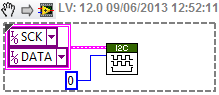
I need to use a heat of TPA81 sensor in my Dani robot project, so I found the 'Devantech TPA81 reading temperature table' example in examples of robotics. I connect my sensor with a USB - I2C converter and then connected to my PC. I run the program, but the problem "the physical channel is not specified" still exists. How to choose the physical channel in labview for the clock channel and the data channel?
Could someone please help me and thank you in advance.
Jason
Hello.
The example given here "Matrix of the temperature read Devantech TPA81", works with acquisition cards supported by the driver "DAQmx" therefore, I think that this will not work with a simple "USB - I2C" converter.
Now, on the other hand, if you just want to work with the "TPA81" sensor in the robot, DANI, you could see the example "Devantech TPA81 (FPGA). Lvprog' in the help of LabVIEW, where, in the "target FPGA", you will find the VI "Devantech TPA81 (FPGA). saw', where you can configure the channels (data and clock). -
How create/get ColorPal driver for LabVIEW?
Hello!
I am a french student in England and I'm working on the Starter Kit 2.0 (with DaNI Robot). My company wants to turn the feature of prevention of obstacle (thanks to the ultrasonic sensor) into a follower of colored (thanks to the Parallax ColorPal) line. So I want to program in LabVIEW but I don't really know how to get the driver ColorPal or screws to connect between the sbRIO 9632 and this color sensor. I use the same yarn as the ultrasonic sensor to connect the ColorPal.
Thanks in advance for your help.
Concerning
Kevin
Hey Kevin,
I took a glance at the ColorPal documentation and it seems that it is programmed using e/s series. As you can see below:
You will need to do, is use series found below the palette of e/s of instrument LabVIEW VISA and functions to communicate with your ColorPal. I recommend that you download their website ColorPal documentation and study the syntax of the commands that you will need.
Also for reference here is a good place to start when programming of VISA.
Kind regards
-
Unable to connect to starter kit 2.0 Robotics
Hi all
I know this question has been askedmultiple times, and I read trough forum messages, but cannot find a solution.
When I try to run a robotics project on DaNI, 2.0 Starter kit, I get a message of conflict resolution, saying "unable to connect to the target. --> See image rasthaus
I installed the latest version of labview, robotics, FPGA modules and in real time as well as pilots of RIO.
Once I disabled my firewall, I was able to detect the robot with MAX, but I was not even able to connect using labview.
Thanks for any help,
MortZxD
Hello
I had the same IP address as illustrated by MAX in my library of projects, but I could not always connect.
I reset the IP address of the robot to start in safe mode and changing an address IP static, dynamic and who did the tour!

Thnks
-
LEGO Self Balancing Robot algorithms
I would get the algorithms & software used for the Lego NXT self balancing
robot that has been demonstrated by us Saha (spelling?) during the FIRST
robotics competition. I searched the site but can't find
information related to the algorithm or even the software. If you
could help provide this information I would be very happy.
Thank you, Jon HaurisI'm not sure of which showed an Anu, but here is a link to a really nice solution of an individual balancing NXT using a gyroscope.
It is a student of the Fachhochschule Nordwestschweiz in Switzerland project. They have created two versions:
- Download VI for the NXT and let it run stand-alone
- Run the VI on the host computer by using a USB to the NXT connection (this way you see all the command parameter more it offers management port)
http://projekte6.FHNW.ch/Technik/EIT/Herbst2007/BruWid/
You will find screws, videos and more on the page of the project (in German).
-
Hello
I am interested in this kit 'DANI'... really I intend to buy it to have on the sbRIO-9632 trained in real-time applications.
My question is after having used this kit in with examples of labview training... I'll be able to use the sbRIO 9632 in another application also for motors continuous command.
I would like to build a project of DC motor Position control
using a mould to tilt mechanism and I think to get use of the sbRIO 9632 and the circuit of engine on this kit and use it to Pan tilt mechanism
I have waiting for a tilting mechanism pan with two engines 12DC, this mechanism also has a pot. for your comments.
I'll go and buy this robot kit and you train?
Am I able to disammble (without losing its function as a robot when gathered) and use the tips (driver sbRIO9632 and motor circuits) need in my project of pan/tilt?
Thanks in advance
The sbRIO on the robot Starter Kit still usable by itself, even if it is removed from the robot. You can use it as any other sbRIO-9632. One thing to keep in mind is that you will need to provide a power supply for the Board once it is removed from the robot. It requres a 19 to 30 VDC power supply.
Regarding your question about to dismantle the robot, there is no reason that this will not work if if it is installed correctly. Do not forget that you would be responsible if yes or no it works once reassembled, because NEITHER does not officially support dismantling the robot. There is no diagrams or instructions (that I know of) to do this.
Chris M
-
I2C + class motor from examples of robotic controller
I try to combine (i.e. to use together in the same project) the motor controller class used in "Starter Kit 2.0 Custom FPGA" with I2C of "Communication I2C - sbRIO" in the examples of the Robotics module.
I have already combined the FPGA code in a single FPGA VI and have tested the two individually. When I go to use them together, I can't use the same FPGA VI reference because one is designed using a FPGA VI reference in dynamic mode (engines) and the other uses an FPGA VI reference that isn't in dynamic mode (I2C).
So, what should I do? I was going to try to convert the I2C in dynamic mode, but the only way I'd be able to do is to open the FPGA reference in each Subvi (since I can't bind to a type in the dynamic mode definition). It also looks like trying to convert each other would be a nightmare because it would require to change the classes also (which is a mystery to me).
P.S. I have sbRIO-9632 (Starter to be transferred to a large robot Kit)
Nathan_B. . I met the same problem, when I mixed the two codes.
And the only way I found to resolve this problem, configure the device "FPGA" in dynamic mode, then create a control and change of the Subvi in relation to the 'I2C Protocol', with this command (replace the input and output of the 'Sub - VI' - reference fpga). In this way, I realize the work programme. (see attachment).
-
I recently started work on DaNI 1.0 Act LabView Robotics Hands-it is available in the Robotics 101 Resource Kit.
I'm stuck at step 11 of exercise 2: Introduction to the LabView environment development.
It says select Bitfile and navigate to this path. Can I'm lost and I was wondering how to get there.
Any help would be greatly appreciated.
Hi Ali,
I'm sorry for the No.
My problem is: I can't find the bitfile in my as project file.
After a lot of research (I did a complete search of the C:\ drive), I found an identical to the bitfile bitfile said in the tutorial.
I find the bitfile in this way:
Discovering Instruments > LabVIEW2010 > examples > Robotics > Starter Kit > Starter Kit roaming > FPGA Bitfiles > StarterKitRoamin_FPGATarget_StarterKitFPGAVI_E8A41200.lvbitx.
I'm using LabVIEW Robotics 2011 Module.
-
Executive differential Robotics
Hello
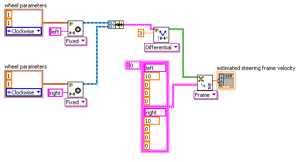
I am an autonomous robot using LabView programming and I'm having a little trouble with the vi «Get the speed of frame of steering wheels»
I narrowed down it to this simple test, which makes a differential direction image, pass a few tests of wheel speeds and reads the estimated speed of weft direction.
As the wheel past the speeds are identical and in the same sense, I suppose that management believes frame speed would be all right (y_dot) with no angular velocity (theta_dot), but the values returned for [x_dot, y_dot, theta_dot] are [0, 4.59618, 8.10573]
Here's what the test looks like.
I have sucessfully used the other direction and communication engine screws without problem.
Any help would be greatly appreciated.
Pierrel,.
I made a change in the direction Robotics API which should solve the problem you are experiencing. Please try these steps, and then let me know if it fixes the problem you see:
- Unzip the contents of the attached zip file into your ""
\National Instruments\ "folder. " - Verify that this file exists: '
\National Instruments\LabVIEW 2010\vi.lib\robotics\Steering\Steering Frame\Estimate speed Transforms.vi ' - Test your application on the desktop and RT. 'Get Steering Frame speed of Wheels.vi' should now return the correct values on the two types of targets.
Chris M
- Unzip the contents of the attached zip file into your ""
-
Download program labview on several robots
Hello
I'm new to LabVIEW and robotics kit. My question is how to download a simple example (avoidance of obstacles) on several robots at the same time. I am able to download separately one by one and it is caught in time. Is there a way in such a way that all the robots with ethernet cables are connected to the switch and controlled at the same time and each of them while giving the ip address or the name of the program?
Thank you
Goutham
Great news. In fact, we have a range of Configuration software in real-time in LabVIEW which can copy the image to a target and then apply this image to other targets.
You can find the palette able IO > System Configuration
What you have to do is copy the image, and then you can download the image to your robots.
This option, or one of the other two should do the job.
Finally, remember that if two starter kit robots are pointing towards each other, the sonar sensors will interfere with each other. If you use the stock starter kit, you can run difficulties running several robots using both the sonar sensor if they will compete.
-
Trace of the end effector of a manipulator Robot in Simulator 3D display
Hi all
I am currently working on a project to control robot on LabVIEW Robotics Module 2013.
In project, I need to show 3D track of the Effector(or an arbitrary point of the last link) in the display of the Simulator.
So so we can easily see the error of monitoring (the diffrerance between the desired trajectory and actual path) on the façade of the Simulator.
I also added a picture of my primitive system to clarify what I needed.
Thank you.
Your photo, it seems that you already have a 3D scene called Simulator display. Is this VI an example that was provided to you? Or have you written this VI?
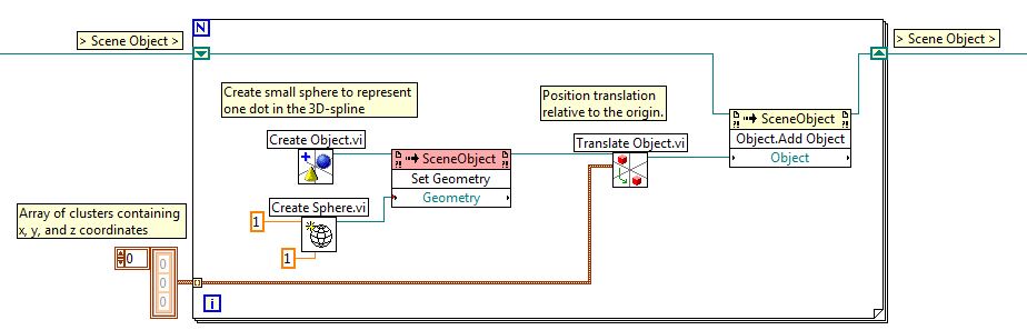
This isn't something I've done before, but assuming that the item titled display Simulator is a 3D scene or a 3D image, you could follow the path of the Effector keeping the Effector 3D locations in a wide range of groups, each with an x, y and z location. 3D scenes/images are used to represent physical objects in a virtual environment, so each location to which you want to trace would become an object. Below is an excerpt where I created a for loop that will create small spheres for each point that is stored in an array of clusters. These spheres are created, moved to the right and then added to the existing 3D scene location.
Your application may be different from what I proposed, but you should start by looking at the example of solar system set out below. This example shows how objects are created, added to scenes and interacts with.
Community: solar system with 3D picture control
-
Hi people.
I'm looking for a with several degrees of freedom robotic arm to hold and tilt an object (s). Objects would vary between about1' x 1 "x 0.1" rectangular objects to maybe length 6 "x 2" diameter cylindrical objects. Weight of objects can be a maximum of 20 lbs.
Robotic arm must be able to withstand up to 225 kV x-rays.
I would like to be able to control such arms with LabVIEW movement solution any.
I know that it is a difficult question but looking to see if maybe someone has an experience that can help.
Sincerely,
Don
Hi Don,
You can take a look at ImagingLab Robotics library for LabVIEW - http://sine.ni.com/nips/cds/view/p/lang/ru/nid/211183
These libraries allows you to use LabVIEW for control of almost all industrial robotic arms produced by Denso, Epson, Kuka, Kawasaki, Mitsubishi, Toshiba and Yaskawa Motoman.You can choose any robotic arm 7 robot manufacturers according to your budget and your needs (in your case, the arm must be able to work in dangerous places). I recommend you contact the local representative of the selected manufacturer or visit their Web sites.
Sincerely,
Nik.
-
Hello
I am trying to simulate a youBot on an envirment just walk right to the difficulty red cell using Robotics Simulation environment. However, there is a problem: it seems comfuse VI 'Set up Steering Frame' with four engines on the youBot engine.
I really want the robot to go straight.
My goal of ultimacy is to implement the plannig of path to the robot.
Could you give me some advice on this?
The project file has been compressed and downloaded.
Thank you very much
It seems to me that similar issues have been postponed and responses on these Forums. Did you do a search in the Forums? Have you looked in the Forum of Robotics?
Bob Schor
Maybe you are looking for
-
I had been in favour of Acer for many years and had used 6 notebooks Acers and destops all because of your excellent after-sales service. I had no problem with the repair spot all these years, but I have a nasty shock today when I bring my 3820TG to
-
I am trying to download music. I did this recently and did not get an error message. I get an error message from windows Wizard extraction saying that before I can retrieve records I should copy the files in the compressed folder. -What this means an
-
Download express outloox for windows 7
What is windows live mail?
-
Errors, linking OFA Standard Page (ArPrtySrchPG) in JDeveloper
Several errors trying to run standard OAF pages (specifically /oracle/apps/ar/cusstd/srch/webui/ArPrtySrchPG and its subpages) since JDeveloper to an extension - ultimately what I have to do is by default certain values on the screen creating account
-
Move the files to the new hard drive
I just bought an external hard drive more. If I move all my images to the new drive with the same folder structure, LR automatically recognizes the files if I give the new drive of the same "letter" (i.e. M :) that old?