Routing of SSL traffic on two firewalls
Hello
I have HT an ASA face internet and destined for SSL connections. Behind the ASA I IOS Firewall that hosts servers must be accessed through the SSL provided by the asa
The issue im having is: Users SSL Vett ends at the ASA fine, after that when I pass this traffic and in the firewall IOS, traffic does not reach the destination servers. Newspapers in ios FW watch suite msg "Crypto packages re - CVD is not crypto IPSEC package"
Please help me how to get these traffic routed via the ssl Protocol on the asa in the ios firewall
I suppose it's possible you an IPSec VPN configured on the IOS Firewall including encryption field includes the one used by the SSL VPN client.
The IOS Firewall has any IPSec VPN configured?
Tags: Cisco Security
Similar Questions
-
Unable to access SSL Web site when company proxy use man-in-the-middle attack to scan SSL traffic
Our company uses a proxy server that analyzes the SSL traffic on web sites. This is done via man-in-the-middle attack. The proxy generates a new certificate on the fly that it sends to the client, impersonate a secure server.
After upgrading from Firefox 10.0, I always get error:
Error HTTP Status: 400 Bad Request
After the confirmation of a security exception.Maybe this is related to the difficulties of the attack of the BEAST bug (browser exploit against SSL/TLS)
- bug 702111 - intolerant servers to record split of 1: n-1. "The connection was reset" (see also the comment 60)
-
This allows traffic between two interfaces ethernet on a PIX
I have a PIX with interface inside, IP 10.198.16.1. It also has an interface called WTS, IP 10.12.60.1. I'm having difficulty to allow traffic from the 10.198.16.0 network to cross the PIX in 10.12.60.0. I'm trying specifically to allow access to a server with an IP address of 10.12.60.2.
I enclose my config. Any help would be greatly appreciated!
OK, so the inside interface has a security level of 100, WTS has a security level of 75, so traffic from inside to WTS is considered outbound traffic, which is allowed by default. All you need is a pair of nat/global (or static) between both interfaces so that the PIX knows how NAT traffic between two interfaces (remember, the PIX do NAT).
You have this in your config file:
NAT (inside) 1 10.0.0.0 255.0.0.0 0 0
who says all traffic inside, interface with the IP 10.x.x.x address will be NAT would have, but you must then a global for the interface WTS define what those IPS will be NAT would.
Adding:
Global (WTS) 1 interface
will be PAT all inside resolves the IP address of the interface WTS and allow traffic to flow between the interfaces. If you prefer the hosts inside the interface to appear as their own IP address on the WTS network, then you can use a static command and NAT addresses themselves, actually doing NAT, but not actually change addresses:
static (inside, WTS) 10.198.16.1 10.198.16.1 netmask 255.255.240.0
Hope that helps.
-
Routing of traffic between two VPN Site-to-Site Tunnels
Hi people,
I am trying to establish routing between two vpn Site-to-Site tunnels which are destined for the same outside the interface of my Cisco ASA.
Please find attached flowchart for the same thing. All used firewalls are Cisco ASA 5520.
Two VPN tunnels between Point A and Point B, Point B and Point C is too much upward. I activated same command to permit security level interface also intra.
How can I activate the LAN subnets traffic behind Point to join LAN subnets behind C Point without having to create a tunnel separated between Point A and Point C
Thank you very much.
Hello
Basically, you will need to NAT0 and VPN rules on each site to allow this traffic.
I think that the configurations should look something like below. Naturally you will already probably a NAT0 configuration and certainly the L2L VPN configuration
Site has
access-list NAT0 note NAT0 rule for SiteA SiteC traffic
access-list allowed NAT0 ip 192.168.1.0 255.255.255.0 192.168.3.0 255.255.255.0
NAT (inside) 0 access-list NAT0
Note L2L-VPN-CRYPTO-SITEB access-list interesting traffic for SiteA to SiteC
access-list L2L-VPN-CRYPTO-SITEB permit ip 192.168.1.0 255.255.255.0 192.168.3.0 255.255.255.0
Where
- NAT0 = is the ACL to be used in the NAT0 rules that will exempt SiteA SiteC NAT traffic
- NAT = is the line of configuration NAT0
- L2l-VPN-CRYPTO-SITEB = LCA in configurations VPN L2L that defines the SiteA LAN to LAN SiteC traffic must use the VPN L2L existing SiteB
Site B
access list OUTSIDE-NAT0 note NAT0 rule for SiteA SiteC traffic
OUTSIDE-NAT0 allowed 192.168.1.0 ip access list 255.255.255.0 192.168.3.0 255.255.255.0
NAT (outside) 0-list of access OUTSIDE-NAT0
Note L2L-VPN-CRYPTO-SITEA access-list traffic for SiteA to SiteC through a Tunnel between A - B
access-list L2L-VPN-CRYPTO-SITEA ip 192.168.3.0 allow 255.255.255.0 192.168.1.0 255.255.255.0
Note L2L-VPN-CRYPTO-SITEC access-list traffic for SiteA to SiteC through a Tunnel between B - C
access-list L2L-VPN-CRYPTO-SITEC permit ip 192.168.1.0 255.255.255.0 192.168.3.0 255.255.255.0
Where
- OUTSIDE-NAT0 = is the ACL to be used in the NAT0 rules that will exempt SiteA SiteC NAT traffic. It is this time tied to the 'outer' interface, as traffic will be coming in and out through this interface to SiteB
- NAT = is the line of configuration NAT0
- L2l-VPN-CRYPTO-SITEA (and SITEC) = are the ACL in the configurations of VPN L2L that defines the SiteA LAN to LAN SiteC traffic should use existing VPN L2L connections.
Site C
access-list NAT0 note NAT0 rule for SiteC SiteA traffic
NAT0 192.168.3.0 ip access list allow 255.255.255.0 192.168.1.0 255.255.255.0
NAT (inside) 0 access-list NAT0
Note list-access-L2L-VPN-CRYPTO-SITEB SiteC to SiteA interesting traffic
L2L-VPN-CRYPTO-SITEB 192.168.3.0 ip access list allow 255.255.255.0 192.168.1.0 255.255.255.0
Where
- NAT0 = is the ACL to be used in the NAT0 rules that will exempt SiteC to SiteA NAT traffic
- NAT = is the line of configuration NAT0
- L2l-VPN-CRYPTO-SITEB = LCA in configurations VPN L2L that defines the SiteC LAN to LAN SiteA traffic must use the VPN L2L existing SiteB
To my knowledge, the foregoing must manage the selection NAT0 and traffic for VPN L2L connections. Naturally, the Interface/ACL names may be different depending on your current configuration.
Hope this helps
-Jouni
-
IP NAT on the router on SSL - VPN appliance
Someone at - it allows to transmit 443/SSL on a SSL VPN Cisco 891 - K9 unit?
(I have never encountered this situation before as the router VPN terminated public face directly or we had several IPs public to assign the VPN device directly a public IP address).
With ' ip nat inside source static tcp 44.55.66.255 443 10.10.10.150 443 extensible "is supposed to pass the SSL request to the appliance SSL VPN to 10.10.10.150 to have VPN applications ended here.
But failed miserably body 891 - K9 created a virtual ARP entry for 10.10.10.150. So two MACs with the same IP address.
So 443 requests were sent to its interface. At the hearing of NAT, I can't ssh inside SSL - VPN, but by the time the statemet disappeared, I can ssh and warning dupliacte ARP goes.
* 1 Nov 19:22:46.871: % IP-4-DUPADDR: duplicate address 10.10.10.150 on Vlan10, a source of aaaa.bbbb.cccc
* 1 Nov 19:23:18.083: % IP-4-DUPADDR: duplicate address 10.10.10.150 on Vlan10, a source of aaaa.bbbb.cccc
* 1 Nov 19:23:48.295: % IP-4-DUPADDR: duplicate address 10.10.10.150 on Vlan10, a source of aaaa.bbbb.cccc
RTR #sh clock
* 19:24:26.487 UTC Sunday, November 1, 2015
RTR #sh ip arp 10.10.10.150
Protocol of age (min) address Addr Type Interface equipment
Internet 10.10.10.150 - e02f.6d96.8dd0 ARPA Vlan10
RTR #sh ip arp 10.10.10.150
Protocol of age (min) address Addr Type Interface equipment
Internet 10.10.10.150 - e02f.6d96.8dd0 ARPA Vlan10
RTR #sh sh ip route 10.10.10.150Cisco TAC to reproduce this problem at the moment to report dev.
Does anyone else have this problem or a workaround?
Thank you.
I may be misunderstanding but isn't your NAT statement backwards IE. If you want traffic to pass to 10.10.10.150 it shouldn't be-
' ip nat inside source static tcp 10.10.10.150 43 43 44.55.66.25x.
isn't the device for SSL connection on interface 'ip nat inside '?
Jon
-
Routing quirks SSL customer VPN - more
I studied SSL VPN-Plus feature on NSX Edge Gateway and I noticed something really weird just how customer VPN traffic is routed. All client TCP connections are NAT'd to closest edge interface address, any other protocol is routed by using the IP address of the affected client Pool of IP.
Example of
Bridge Board with two interfaces
-outdoor = x.x.x.x
inside-a = y.y.y.y
VPN client
-IP address = z.z.z.z
Ping ICMP customer VNP with IP address z.z.z.z arrives at its destination with IP address z.z.z.zUDP DNS queries to customer VNP with IP address z.z.z.z arrives at its destination with IP address z.z.z.z
Application of TCP HTTPS client VPN with IP address z.z.z.z arrives at its destination with the IP edge gateway interface address y.y.y.y
I have no NAT configuration defined by the user in place, only NAT rule is rule DNAT system default for the external interface (uplink).
That's serious problem with SSL VPN-Plus, I filed a request for support if could, but since I am a student help on licenses NFR partner without support I can't.
Ed. also tested the UDP
There is a flag in configuration edge-> sslvpn-> private networks-> specific entry-> 'enable TCP optimization '.
Disable that and you will see even the client ip TCP connections.
Dimitri
-
Is it possible to route signals of relaxation between two chassis PXI-1002 with the PXI-8335?
Hello
as the subject says, I am interested in the delivery of a signal to trigger between two chassis PXI-1002. At present, these two chassis are connected by a MXI - 3 system using maps PXI-8335. The software is Labview 2010 sp1 and 380 NIScope drivers.
We want to keep (a PXI-5122 by chassis) scanners supply separated due to the requirements of our measure! The chassis are connected via cable to fiber optic. This explains why I can not just use the shutter release in Star, or connect via 'Trigger' or 'clk' cards (the inputs / outputs to the front of the cards).
I found a few examples, but they seem to all be designed for use with a chassis only, I'll call later to the examples that inspired me to this point. Each guide explaining the synchronization of several chassis systems seems to use another material or VI is not accesible to me. This makes me wonder if my hardware has the capacibilities I need.
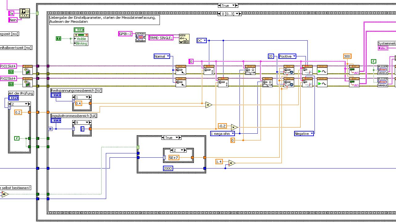
The first picture shows approximately where I started from (sorry I can't post VI, confidential...):
Only the middle part is interesting. Two sessions are initialized and manipulated parallel, trigger too. This has led to delays in the signals and should now be fixed. This apart from the VI works fine.
Goal is to trigger only on one channel but both devices! If possible, the device will trigger must be chooseable.
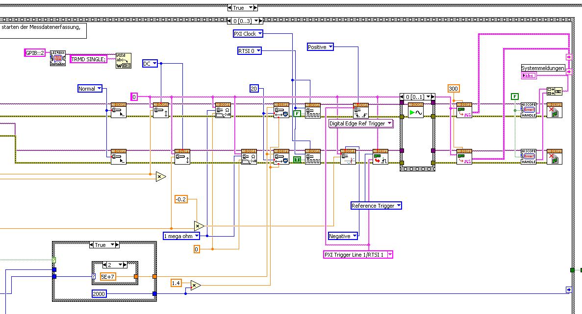
I started to rebuild the VI using the "EX Synchronization.vi 5xxx niScope' seeming spontaneity. The result is shown in the following image:
I tried different RTSI lines, but had no positive results. only the main channel has triggered.
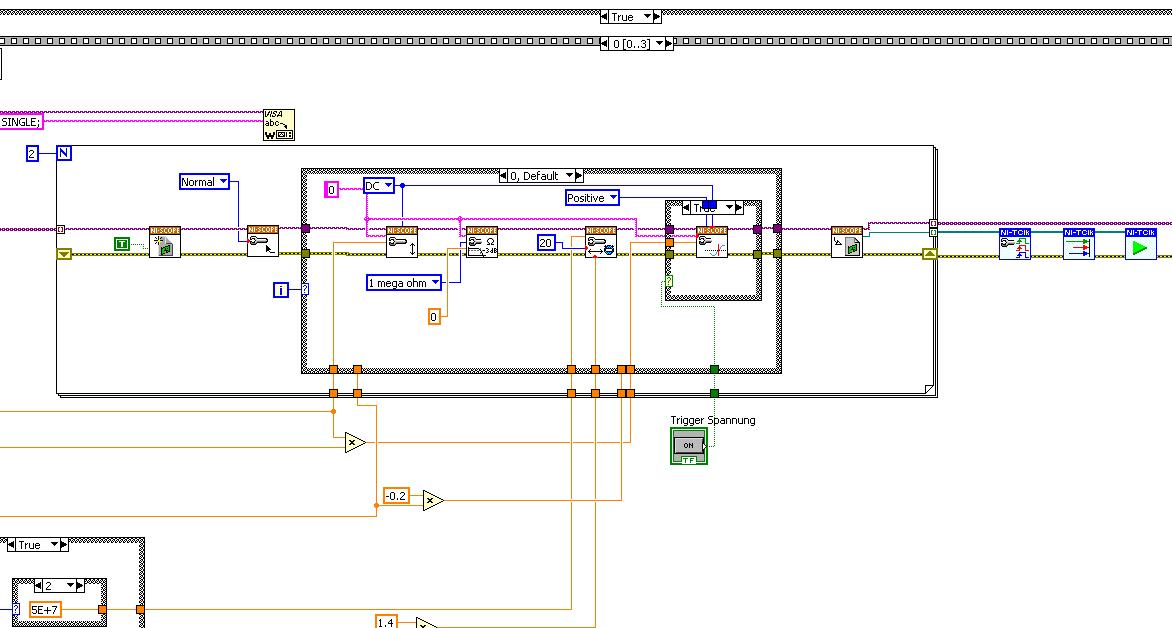
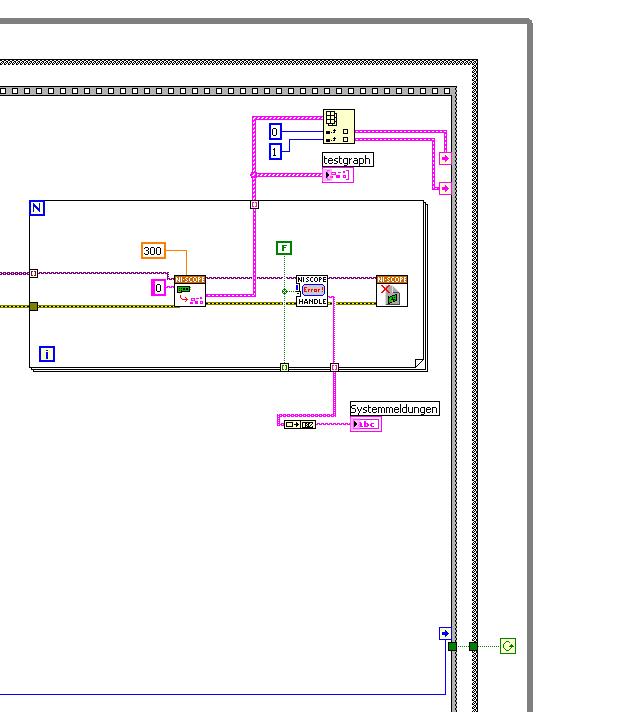
After this first approach, I looked in the "niScope EX .vi multi-Device configured Acquisition (TClk)" and other examples of TClk which seem to work for similar problems. The VI of reconstruction can be seen in the following images:
(Sorry, I had to use two photos..)
In this case, I didn't have no choice for trigger lines, it would automatically set the VI TClk. I tried to trigger on both devices, though. This second approach seemed promising to me, but it was an error:
"niTClk Synchronize.vi:1".
Index (starting at zero) of the session: 1
The error reported by the pilot of the instrument:
No registered trigger could be found between the
devices on the route.If you have a PXI chassis, the chassis correctly identify in
MAX and make sure that it has been configured correctly. If you use PCI
devices, make sure they are connected with a RTSI cable and that the cable RTSI
is saved to the MAX. Otherwise, make sure that there is an available trigger line
the trigger bus shared between devices.Source device: PXI1Slot4
Target unit: PXI2Slot4
Status code:-89125niTClk Synchronize.vi:1
Index (starting at zero) of the session: 1
The error reported by the pilot of the instrument:
No registered trigger could be found between the
devices on the route.If you have a PXI chassis, the chassis correctly identify in
MAX and make sure that it has been configured correctly. If you use PCI
devices, make sure they are connected with a RTSI cable and that the cable RTSI
is saved to the MAX. Otherwise, make sure that there is an available trigger line
the trigger bus shared between devices.Source device: PXI1Slot4
Target unit: PXI2Slot4
"Status code:-89125"
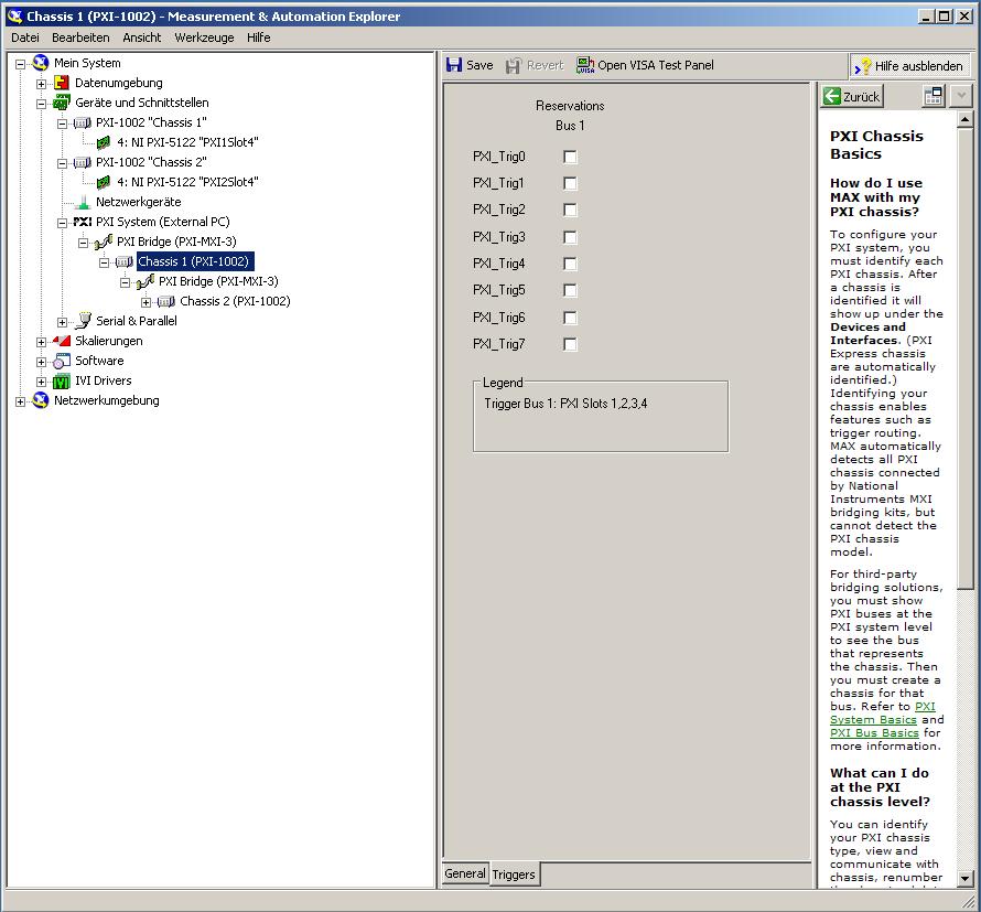
This error came back even after I've identified this drug as possible to the MAX, as shown in the screenshot:
In some of the textbooks, they showed how to get the MAX trigger lines, but as you can see, there is only booking options in my MAX. Whatever I do, I can't find options to define how to get my trigger signals...
In principle, it is possible to trigger instruments in different chassis, which is indicated in this Guide and others... the question that remains is can it be done with my set of components?
I understand that the use of multichassis compromised the integrity of the lines very adjusted as trigger in Star etc., so the configuration should be taken into account in some way, that my approach does not, I knew... But there must be a way to do this? And to start: to get just any signal from one device to the other trigger!
For any advice on this issue, I would be very thanfull!
Concerning
Max1744
Hi Max,.
Thanks for the detailed post and explanations of your application and requirements. You're right using TClk, because this is the optimal method to synchronize the 5122 digitizers. The original VI you worked with is unique for some of the legacy scanners and does not directly work with scanners based on the most recent CMS (for example the 5122). The good news is that you can synchronize these cards to separate chassis, but it will use the calendar 66xx and synchronization (T & S) cards in the chassis of the master and the slave, as indicated in the guide that you have accessed. These are needed because a common reference clock must be shared between them as well as a couple of tripping. MXI itself can not handle export triggers and clocks, so there is no way to do this without physically wiring between the chassis with cards T & S. Unfortunately, regardless of what specific method, you use for synchronization, it will take a material extra beyond what you currently have.
As one of your needs looks like it is necessary to retain wiring between the chassis directly, you may need to consider to synchronize using 1588 or GPS protocols. 1588 Protocol is a system for synchronization on the network while GPS course use antennas and locks for a common wireless signal. Although these synchronization methods may allow you to keep your chassis isolated, they will also require some manual configuration because you would be able to use the TClk synchronization and so the level of synchronization you can get between the cards may not be as good that can physically wire signals between the chassis using T & S cards.
Hope this helps,
-
ACLs on Cisco router - block outside traffic, allow all inside
Hello
I am creating the ACL on the router Cisco that will allow all traffic within internet and don't allow specific traffic on the internet inside.
This is what I have configured and puted on the interface of the router connected to the ISP:
10 permits all icmp (411 matches)
20 permit tcp "my public IP address" no matter what eq 3389 (46400 matches)
30 permit tcp "my public IP address" no matter what eq 22 (9185 matches)
40 "my public IP address" ip allow match any (3207)
50 permit tcp any any eq smtp (11 matches)
60 permit tcp any any eq www (56 matches)
70 permit tcp any any eq 443 (29 items)
80 permit tcp any any eq field (5 matches)
allowed 81 UDP everything no matter what field of eq (7 matches)
allowed 82 UDP any eq (10564 matches) field
83 permit tcp any what eq field everything (10 matches)
90 permit udp any any eq ntp (13317 matches)
95 permit tcp 192.168.0.0 0.0.0.255 anyDialer interface 1
IP Access-group 101 IN
So I can connect to my public IP to the LAN of the customer via RDP and SSH (which is OK), but users of the client cannot access Internet (which is not OK.)!
Users are all in the same Vlan. Between the interface Vlan and outside interface (dialer 1) Pat.
There is no other ALC on the router except for PAT.
What I'm missing here?
Thank you.
Is this why 192.168.0.0/24 is present in the list of ACL 101? What is the remote subnet that you connect to port 3389?
If your local subnet interior is a soldier of the C class, it must be your global external address you want to add to the ACL 101.
Better yet, run an IPSec tunnel between the sites.
-
Try to route all ipsec traffic
Hello
Can anyone help me please with config below. I am trying to route all traffic (web browsing) by the router.
For now I can connect to the vpn and browse the network, but users cannot resolve web pages (page loading without end). If I activate split tunnel web browsing works but not what I'm used to.
LAN pool 192.168.10.0/24
local pool 192.168.20.0/24
I assume it has something with ACL and NAT, but I can't understand that.
Config is attached.
Thank you.
I think your config should work.
The router which model is it and what version of software you are running?
-
DMZ-Link bandwidth does not change the routing table countin traffic
Hey guys
I'm INE laboratories dong and shoved a weird one that delivers.
I have configured the dmz-link bandwidtha nd the extended communities to send, I get the bandwidth in the BGP routes, however the routing table does not change the proportion of traffic according to the bandwidth available link.
Here is my configuration:
Rack1R6 (config) #do sh run | dry BGP
router bgp 100
no synchronization
The log-neighbor BGP-changes
BGP dmzlink-bw
155.1.146.0 netmask 255.255.255.0
aggregate-address 155.1.0.0 255.255.0.0 summary only
neighbour 54.1.1.254 distance-54
neighbor 54.1.1.254 dmzlink-bw
neighbour 155.1.67.7 distance-300
neighbour 155.1.146.1 distance-100
155.1.146.1 neighbor send-community times
No Auto-resume
Rack1R6 (config) #.
Rack1R6 (config) #do sh ip bgp neigh 155.1.146.1 opponents
Version of BGP table is 35, local router ID is 150.1.6.6
Status codes: deleted, cushioning d s, history of h, * valid, > best, i - internal.
r SIDE-failure, stale S
Source codes: i - IGP, e - EGP,? -incomplete
Network Next Hop path metrics LocPrf weight
* > 28.119.16.0/24 54.1.1.254 0 54 I
* > 28.119.17.0/24 54.1.1.254 0 54 I
* > 112.0.0.0 54.1.1.254 0 0 54 50 60 I
* > 113.0.0.0 54.1.1.254 0 0 54 50 60 I
* > 114.0.0.0 54.1.1.254 0 0 54 I
* > 115.0.0.0 54.1.1.254 0 0 54 I
* > 116.0.0.0 54.1.1.254 0 0 54 I
* > 117.0.0.0 54.1.1.254 0 0 54 I
* > 118.0.0.0 54.1.1.254 0 0 54 I
* > 119.0.0.0 54.1.1.254 0 0 54 I
r > 155.1.0.0 0.0.0.0 32768 I
Rack1R6 (config) #do sh ip bgp
Version of BGP table is 35, local router ID is 150.1.6.6
Status codes: deleted, cushioning d s, history of h, * valid, > best, i - internal.
r SIDE-failure, stale S
Source codes: i - IGP, e - EGP,? -incomplete
Network Next Hop path metrics LocPrf weight
* i28.119.16.0/24 204.12.1.254 0 100 0 54 I
*> 54.1.1.254 0 54 i
* i28.119.17.0/24 204.12.1.254 0 100 0 54 I
*> 54.1.1.254 0 54 i
* i112.0.0.0 204.12.1.254 0 100 0 54 50 60 I
* > 0 0 54 50 60 54.1.1.254 I
* i113.0.0.0 204.12.1.254 0 100 0 54 50 60 I
* > 0 0 54 50 60 54.1.1.254 I
* i114.0.0.0 204.12.1.254 0 100 0 54 I
*> 54.1.1.254 0 0 54 i
* i115.0.0.0 204.12.1.254 0 100 0 54 I
*> 54.1.1.254 0 0 54 i
* i116.0.0.0 204.12.1.254 0 100 0 54 I
*> 54.1.1.254 0 0 54 i
* i117.0.0.0 204.12.1.254 0 100 0 54 I
*> 54.1.1.254 0 0 54 i
* i118.0.0.0 204.12.1.254 0 100 0 54 I
Network Next Hop path metrics LocPrf weight
*> 54.1.1.254 0 0 54 i
* i119.0.0.0 204.12.1.254 0 100 0 54 I
*> 54.1.1.254 0 0 54 i
r i155.1.0.0 155.1.146.4 0 100 0 I
r> 0.0.0.0 32768 i
s > 155.1.146.0/24 0.0.0.0 32768 0 I
* > i205.90.31.0 155.1.13.3 0 100 0 200 254?
* 155.1.67.7 0 300 200 254?
* > i220.20.3.0 155.1.13.3 0 100 0 200 254?
* 155.1.67.7 0 300 200 254?
* > i222.22.2.0 155.1.13.3 0 100 0 200 254?
* 155.1.67.7 0 300 200 254?
Rack1R6 (config) #.
# now R4 configuration
Rack1R4 (config) #do sh run | dry BGP
router bgp 100
no synchronization
The log-neighbor BGP-changes
BGP dmzlink-bw
155.1.146.0 netmask 255.255.255.0
aggregate-address 155.1.0.0 255.255.0.0 summary only
neighbour 155.1.45.5 distance-200
155.1.45.5 route-neighbour card GAME-54 on
neighbour 155.1.146.1 distance-100
155.1.146.1 neighbor send-community times
neighbour 204.12.1.254 distance-54
neighbor 204.12.1.254 dmzlink-bw
No Auto-resume
Rack1R4 (config) #.
Rack1R4 (config) #do sh ip bgp Synt.
Local router BGP 150.1.4.4 identifier UNDER number 100
BGP table version is 18, table 18 main routing version
15 entries for network using 1980 bytes of memory
18 entries for path using 936 bytes of memory
9/7 BGP path/bestpath attribute entered using 1512 bytes of memory
3 entries for BGP AS-path ACCESS using 72 bytes of memory
1 entries PMO community, using 24 bytes of memory
0 cache entries of BGP route-map with 0 bytes of memory
0 cache entries of filter-list BGP using 0 bytes of memory
Bit entries in the cache field: 3 courses (up to 5) with 96 bytes of memory
BGP using 4620 total number of bytes of memory
Activity 102/87 BGP prefixes, 243/225, scan interval to 60 seconds
Neighbor MsgRcvd MsgSent V AS TblVer InQ OutQ Up/Down State/PfxRcd
155.1.45.5 4 200 8615 8640 18 0 0 07:38:02 3
155.1.146.1 4 100 8761 8668 18 0 0 00:14:34 3
204.12.1.254 4 54 8724 8595 18 0 0 07:38:02 10
Rack1R4 (config) #do sh ip bgp
BGP table version is 18, local router ID is 150.1.4.4
Status codes: deleted, cushioning d s, history of h, * valid, > best, i - internal.
r SIDE-failure, stale S
Source codes: i - IGP, e - EGP,? -incomplete
Network Next Hop path metrics LocPrf weight
* > 28.119.16.0/24 204.12.1.254 0 0 54 I
* > 28.119.17.0/24 204.12.1.254 0 0 54 I
* > 112.0.0.0 204.12.1.254 0 54 50 60 I
* > 113.0.0.0 204.12.1.254 0 54 50 60 I
* > 114.0.0.0 204.12.1.254 0 54 I
* > 115.0.0.0 204.12.1.254 0 54 I
* > 116.0.0.0 204.12.1.254 0 54 I
* > 117.0.0.0 204.12.1.254 0 54 I
* > 118.0.0.0 204.12.1.254 0 54 I
* > 119.0.0.0 204.12.1.254 0 54 I
* > 155.1.0.0 0.0.0.0 32768 I
s > 155.1.146.0/24 0.0.0.0 32768 0 I
* i205.90.31.0 155.1.13.3 0 100 0 200 254?
*> 155.1.45.5 0 200 254 ?
* i220.20.3.0 155.1.13.3 0 100 0 200 254?
*> 155.1.45.5 0 200 254 ?
* i222.22.2.0 155.1.13.3 0 100 0 200 254?
Network Next Hop path metrics LocPrf weight
*> 155.1.45.5 0 200 254 ?
Rack1R4 (config) #do sh ip bgp neigh 155.1.146.1 opponents
Rack1R4 (config) #do sh ip bgp neigh 155.1.146.1 opponents
BGP table version is 18, local router ID is 150.1.4.4
Status codes: deleted, cushioning d s, history of h, * valid, > best, i - internal.
r SIDE-failure, stale S
Source codes: i - IGP, e - EGP,? -incomplete
Network Next Hop path metrics LocPrf weight
* > 28.119.16.0/24 204.12.1.254 0 0 54 I
* > 28.119.17.0/24 204.12.1.254 0 0 54 I
* > 112.0.0.0 204.12.1.254 0 54 50 60 I
* > 113.0.0.0 204.12.1.254 0 54 50 60 I
* > 114.0.0.0 204.12.1.254 0 54 I
* > 115.0.0.0 204.12.1.254 0 54 I
* > 116.0.0.0 204.12.1.254 0 54 I
* > 117.0.0.0 204.12.1.254 0 54 I
* > 118.0.0.0 204.12.1.254 0 54 I
* > 119.0.0.0 204.12.1.254 0 54 I
* > 155.1.0.0 0.0.0.0 32768 I
* > 205.90.31.0 155.1.45.5 0 200 254?
* > 220.20.3.0 155.1.45.5 0 200 254?
* > 222.22.2.0 155.1.45.5 0 200 254?
Total number of prefixes 14
Rack1R4 (config) #.
# and where is the real problem, R1
Rack1R1(config-Router) #do sh ip bgp
Version of BGP table is 15, local router ID is 150.1.1.1
Status codes: deleted, cushioning d s, history of h, * valid, > best, i - internal.
r SIDE-failure, stale S
Source codes: i - IGP, e - EGP,? -incomplete
Network Next Hop path metrics LocPrf weight
* i28.119.16.0/24 54.1.1.254 0 100 0 54 I
* > I 204.12.1.254 0 100 0 54 I
* i28.119.17.0/24 54.1.1.254 0 100 0 54 I
* > I 204.12.1.254 0 100 0 54 I
* i112.0.0.0 54.1.1.254 0 100 0 54 50 60 I
* > I 204.12.1.254 0 100 0 54 50 60 I
* i113.0.0.0 54.1.1.254 0 100 0 54 50 60 I
* > I 204.12.1.254 0 100 0 54 50 60 I
* i114.0.0.0 54.1.1.254 0 100 0 54 I
* > I 204.12.1.254 0 100 0 54 I
* i115.0.0.0 54.1.1.254 0 100 0 54 I
* > I 204.12.1.254 0 100 0 54 I
* i116.0.0.0 54.1.1.254 0 100 0 54 I
* > I 204.12.1.254 0 100 0 54 I
* i117.0.0.0 54.1.1.254 0 100 0 54 I
* > I 204.12.1.254 0 100 0 54 I
* i118.0.0.0 54.1.1.254 0 100 0 54 I
Network Next Hop path metrics LocPrf weight
* > I 204.12.1.254 0 100 0 54 I
* i119.0.0.0 54.1.1.254 0 100 0 54 I
* > I 204.12.1.254 0 100 0 54 I
* i155.1.0.0 155.1.146.6 0 100 0 I
* > I 155.1.146.4 0 100 0 I
* > 205.90.31.0 155.1.13.3 0 200 254?
* i 155.1.45.5 0 100 0 200 254?
* > 220.20.3.0 155.1.13.3 0 200 254?
* i 155.1.45.5 0 100 0 200 254?
* > 222.22.2.0 155.1.13.3 0 200 254?
* i 155.1.45.5 0 100 0 200 254?
Rack1R1 (config - Router) # do sh ip bgp 112.0.0.0
112.0.0.0/8, version 4 BGP routing table entry
Paths: (2 available, best #2, table by default-IP-Routing-Table)
MPIO: eBGP iBGP
Announced for the update-groups:
1 2
54 50 60, (from a customer-RR)
54.1.1.254 (metric 2560002816) of 155.1.146.6 (150.1.6.6)
Origin, IGP, 0, 100, valid, internal multipath localpref metric.
DMZ-Link Bw 250 KB
54 50 60, (from a customer-RR)
204.12.1.254 (metric 2560002816) of 155.1.146.4 (150.1.4.4)
Origin, IGP, metric 0, localpref 100, valid, internal, multipath, best
DMZ-Link Bw 12500 KB
Rack1R1(config-Router) #do sh ip route 112.0.0.0
Routing for 112.0.0.0/8 entry
Known through 'bgp 100', 200, 0 distance metric
54, internal type tag
Last update of 204.12.1.254 ago 00:15:30
Routing descriptor blocks:
204.12.1.254, 155.1.146.4, there is 00:15:30
Path metric is 0, number of shares of traffic 1
AS hop 3
Beacon road 54
* 54.1.1.254, 155.1.146.6, there is 00:15:30
Path metric is 0, number of shares of traffic 1
AS hop 3
Beacon road 54
Rack1R1 (config - Router) #.
as you can see, the BGP process in R1 receives the correct link DMZ bw but not indeed take...
can you please help me if I makeover anything in my setup?
Hello
Can you please make sure you have a value of bandwidth on ALL your BGP peering physical interfaces? And you can also include the running-config 'router bgp XXXX' out of R1 as you have not understood what we (others are). Just to make sure that you have "bgp dmzlink-bw' configured on all peerings and overall in the process - it will still show in the output of the same community if it does not work on it.
-
RV180 VPN route all internet traffic via IPSec VPN
Hello
I install my RV180 to VPN to our headquarters Fortigate 60 C. It works really well
My only problem is that I don't know how to move internet traffic on our remote site by Headquarters. We want to use this technique so that all sites have the same web content filtering provided by our main Fortigate unit. I see clearly that all traffic destined to our internal network will go trough the VPN tunnel, but internet traffic will go through our modem at the remote site.
My way of fortigate thinking said that I need a static route to transfer all traffic through the VPN tunnel. I've read elsewhere that I need to set up some sort of ACL.
Anyone else has any ideas on this / has anyone successfully implemented somehting similar?
Hi Jared,
I don't think that RV180 takes complete care of tunneling. Complete tunneling allows you to all your traffic to VPN. RV180 made only split tunneling.
Thank you
Vijay
Sent by Cisco Support technique iPad App
-
Hub and spoke VPN network traffic between two points talked
Hi, I have a star VPN network topology, and all traffic is remote office to the data center,
I have a request to build a tunnel between two remote sites to access some servers between two remote sites,
Can I just change the ACL of valuable traffic to to include say a Cabinet to Office B in rule Cabinet a Datacenter and Office B tunnel to tunnel data center.
In doing so, I can avoide the tunnel between two offices (and B)
See you soon
Hello
You can make the traffic between the two rays go through the hub or build a new tunnel between the rays.
If the hub is an ASA you must authorize same-security-traffic intra-interface permits
If the hub and the spokes are routers, you can also use DMVPN to dynamically create a tunnel between the spokes when necessary.
Federico.
-
Hi allCurrently we have a site, a Vcenter configuration, but we have 5 offices connected via a WAN. At the moment I have just replicating servers on Site 1 in a local backup store. On Site 1, vCenter and the unit of replication are installed locally.
My question is:-if I replicate a server in Site 2 Site 3 will pass all traffic via Site 1? I understand some of the traffic will go down the pipes of the device controlling the work updates and vcenter is stats etc, but I don't want to do is start to seed a drive of 20 GB of site 2 site 3 and then realize actually everything goes through 2 > 1 > 3 - If you get what I mean!
Thanks in advance
Stuart
5.1 if you are NOT of SRM and always use VR "standalone" then traffic will pass through the device at a time. It is one of the disadvantages of the use of VR stand-alone IE limited to one device per vCenter in this kind of design. Thus, even after the initial synchronization task deltas of ongoing replication will still have to go via site1 reach training3 site assuming that you have the device located in site1.
the good news is that this WILL change in 5.5. 5.5 we will allow you to deploy > 1 camera with VR even when used in stand-alone mode. This means in your example, you can deploy 3 devices at least so to Site1 to Site2 and another to training3. Now when you set up replication of Site2 training3 just select unit training3. Once upwards and running replication traffic will now flow Site2 to training3 for VM configured this way and do not have to route back to Site1.
As a shameless plug we really focused on this limitation 5.1 and then subsequently showed the new option of 5.5 in a session vmworld than me and a colleague delivered the week last in San Francisco, second session in this list:
-
Router Cisco SSL VPN Configuration
Hello support.
A question concerning this scenario.
One of our clients has currently SSLVPN enabled for remote users and I was wondering if there is anyway to configure a remote Cisco router to connect via IPSEC at this endpoint SSLVPN? the idea is simply to set up the tunnel without requiring changes on my end of customers.
Thanks in advance.
Ivan Chacon
Hello
IPSEC and SSLVPN are 2 different configurations, there is no way to have a router configured for IPSec and connect to another without changing this end as well. You can run IPSec and SSLVPN on the same router, however.
There are a lot of IOS Lan to Lan configuration guides, or if you want the router to act as a client, are looking to make EZVPN.
HTH
-Jason
-
When I go to the "network and sharing" and try to disable file sharing, it automatically turns on the Windows Firewall. I want to be able and disable file sharing and disable the Windows Firewall (I use Norton 360 firewall). Any ideas? Thank you.
Hello
Check this box
How to enable file sharing enabled or disabled in Vista
http://www.Vistax64.com/tutorials/126388-file-sharing-turn-off.htmlIf no joy collate Support Norton/Symantec and Forums
Norton support
http://www.Symantec.com/support/index.jsp
http://www.Symantec.com/Norton/support/DTree.jsp?PVIDNorton forums
http://community.Norton.com/Norton/?category.ID=NISI hope this helps.
Rob - bicycle - Mark Twain said it is good.
Maybe you are looking for
-
Can how I recover my password iCloud
-
HP Pavilion 15: Screen must COMPLETELY gray - Start Up - cut
Product no.: P3C83PA Serial number: (deleted content) Edition: Windows 10 home System type: 64-bit Screen - TOTALLY GRAY - you can't see a thing of START UP - to SHUT DOWN Kind regardsSonia McMahon
-
How can I make the screen keyboard on disappear?
How can I make the screen keyboard on disappear?
-
Involuntary conversion of files Wordpad Notepad
Windows (XP) has recently begun unexpectedly convert my Notepad files in Wordpad files. I have create a Notepad & save it as .txt. Re - open immediately and it's on Wordpad. DON'T WANT! What happened & how can I restore it?
-
How is it that when I click on clear form Acrobat is option clears all fields populated by a JavaScript document level and if I save them the start of the JavaScript document level form is no longer works?