RS232 port on the cRIO-9074
Hello everyone!
I have a cRIo-9074, with on the frame a RS232 port. I'm trying to use it, but without success... I have already installed NI-Visa. But what do I do now? When I create a new project, I can't find the serial port, and I can't find a tutorial for this...
Thank you very much.
Simon M, starting in Labview and cRIO.
Hello smichau,
This problem was already forum dealt with several in is not this one.
http://forums.NI.com/T5/LabVIEW/cRIO-serial-port/TD-p/1145870
I wish you a good day,
Kind regards
Tags: NI Hardware
Similar Questions
-
UDP communication via secondary ethernet port on the cRIO-9074 problem.
Hi guys.
I connected my host pc running LV 2010 my cRIO-9074 port using a main ethernet crossover cable. I want to use the second port ethernet on the cRIO-9074 to read UDP messages, and I want to access these messages on my host. UDP messages are sent from a local network, but for testing I also use a second pc running LV 2010 to send UDP messages.
I configured the ethernet on the cRIO-9074 ports according to this tutorial: "knowledge base 4E0DGASK: Configure the Ports of double Ethernet on real-time controllers'." " My host and primary ethernet port belong to 'Subnet A' while the second port and the second computer, sending UDP messages belong to 'Subnet B' (at the end of my post I will list the masks of ip addresses and the subnet).
For simplicity, I used the VI´s of this example as a basis for UDP communication. The "UDPServerOnRemoteTarget.vi", which broadcast messages UDP, will run on the secondary computer. The "UDPClientOnRemoteTarget.vi", which reads messages UDP, will work on my host pc.
Now, in the 'UDPServerOnRemoteTarget' VI, you must specify two IP addresses (port # remained unchanged at 3363):
1: the IP address of the ethernet port that will be broadcast UDP messages.
2: the IP address of the ethernet port that will receive the messages.
In the #1 case I put the IP address to the IP address of the ethernet on the secondary pc port.
At the #2 I tried to set the intellectual property: a) IP address of the secondary ethernet port on the cRIO, b) IP address of the ethernet on my host computer port and c) IP address of the primary ethernet port on the cRIO.
None of the parameters produced results. I also tried to change the port number, which did not help.
However, if I bypass the cRIO and connect the host pc and the secondary computer directly (by using a cable crossed a regular cat5 ethernet cable), I am able to send and receive UDP messages (the two stand-alone always are on different subnets). I guess that this at least excludes any fault in the VI´s code.
Does anyone know what I'm doing wrong here? Is it possible at all to read the UDP messages that are sent to the secondary ethernet port on the cRIO my host pc?
I have searched the entire site OR and forums, but didn't come through all that solved my problem. Most of the other tutorials configuration resembling my case is to import the device sends UDP messages in the project, but which is clearly not possible in my case, or is it?
My IP settings are:
cRIO 9074:
Primary ethernet port: 169.254.62.215
Secondary ethernet port: 192.168.0.102 (static)
Host PC: 169.254.58.4
Secondary PC: 192.168.0.144 (static)
SubnetMask on all ports are the value 255.255.0.0
I hope someone out there can help me out.
Kind regards
Phat
Solved.
Stupid mistake. I was running the VI on the host instead of the cRIO pc, which explains why direct communication between the computers worked. Everything works well when it is compiled for the cRIO.
Kind regards
Phat
-
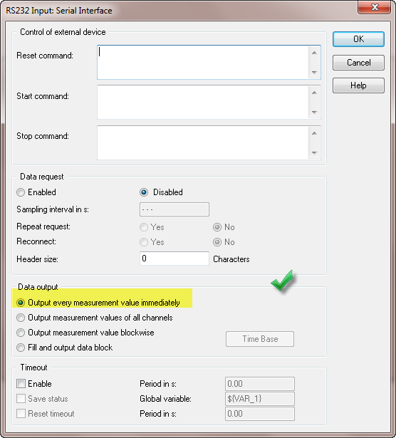
I can collect data from a hygrometer in a text file using the RS232 port with the following T75.2F:H17.0% format, these data are collected using a data logger software. I was wondering if I can collect this data for later analysis using Dasylab. Any help is appreciated.
The setting below causes the error. Change for the second selection, output values of all channels.
-
Hi, just got my new cRIO-9067. I have converted my project over the cRIO-9067 since the cRIO 9074. Same layout module, same engine, same scan code custom fpga, (hybrid mode). I have no problem of compilation for the 9074, which is a lower performance FPGA architecting the 9067 FPGA.
The final timetable for windows compilation shows that the timing is respected for all clocks - 40, 80 and 120 MHz (I use a clock derived for some code sctl). During the end of compilation, during the phase of gen bitfile, I get the dreaded time violation. Investigation of the breach indicates that it is not the custom code, it is not schema components. One of them seems to be linked to the card series OR 9870 I in the chassis.
Why? Is there anything I can try with the compiler directives for this problem? You would think that it would be easier to compile for the highest performance FPGAS...
OK, don't ask me how I thought this output - to run I changed nothing else than this: feed the I/O node a reference FPGA of e/s instead of configure the node via the menu "link to. It makes no sense, but the compilation succeeded when I did this.
I know it is because I created a very simple test VI in my project and made sure it does not compile without it.
-
Connection cRio 9074 second port ethernet to another device via VISA
I'm trying to connect a DAQ Yokogawa system to a cRio 9074 via the second ethernet port. I activated the second ethernet port of the cRio with a static IP address on the same subnet as the data acquisition system. I installed the driver NI-VISA and NOR-SERIAL on the cRio. I can compile the code on the cRio and I'm sure that the code works when I connect to the acquisition of data to a PC. I get an error on the open VISA VI.
Am I missing something or is it not possible to connect the second ethernet port on the cRio in this way?
Thank you
Thank you for your response. I found the same information that you provide, but decided to give it a try.
A few minutes ago, I was able to perform communication between the cRio 2nd access Ethernet DAQ Yokogawa. I managed to do it using the VISA controls. To communicate with the host PC, I get the information of the DAQ with the cRIO as described above and then use shared variables to publish data on the network connected through the first ethernet port.
If anyone wants to reproduce it just to make sure that the two ethernet ports are configured with IP addresses on different subnets that are configured for TCP communication. If more details are to be simply send me a message.
Kind regards!
-
The cRIO serial port can be used for the CAN bus communication?
I would like to order a CVC with a CAN of network device and would like to know if this can be accomplished by using a serial port integrates the cRIO (OR cRIO-9024 in my case). Is it possible, or would need a C Series module CAN?
You need a C Series module. Series and CAN use a DB9, but they do not have the same physical layer.
-
How many IRQS are available on cRIO 9074?
How IRQS are available on the cRIO 9074?
I'm sure it's obvious somehwere for most people, but I can't seem to find it.
-Joe
I couldn't even find it online either. There are 32 total, #0 to #31. I'll look into the creation of the online documentation...
-
How to set up a type of thermocouple in FPGA on cRIO 9074 + modules 9211
Hi all.
Could someone displays an example of VI pour set the type of a module 9211 thermocouple mounted on a cRIo9074 + ethercat 9144.
After several searches on the forum or in the various labviews, I have nothing concrete to this topic.
FYI, I realize a project to track T ° on a machine using the cRIO 9074 + ethercat with display on a Touch Panel (touch screen).
All scan mode in works well. Plug-in of the shared variables to send different surveys on a corporate network so that the Panel button can display this information. A remote PC of supervision may also fetch the info.
My problem today is to be able to choose the type of thermocouple perono LUN VI without having to him by ironing my project and deployment of my modules after changes.
Thanks in advance.
Thanks for the reply.
I had already seen this example but I thought that there was some chose more "simple".
I'm going to use up to 9 modules 9211, which will fatten the VI but it should go.
Thanks again.
-
Use the cRIO as output RS232 port
Hello
I'm working on a cRIO-9002 with a NI9215 AI module. I send the command to the cRIO by an ethernet cable and I read signals of external devices with the module to HAVE it.
My question is about the cRIO RS232 port, I know if I can use it to send data of FPGA for PC? And if I can, how?A quick response will be great, just to drive me on the right track.
Thank you.
Maxim
That should be no problem for you. I would use normally tcp to make the comms but of course series is possible.
Michael -
How can I connect the HOST PC COM port under cRIO 9074?
I can't find any HOST PC COM port on my cRIO.
I tried to use the global variable, but it was useless. Is there a solution?
sad0000 wrote:
I can't find any HOST PC COM port on my cRIO.
And why should he? A cRIO is really another computer. You expect your PC to see serial ports to another PC on your network? No, you wouldn't.
If you really want the cRIO again the serial port of the PC communication, then you will have to apply on the PC that can communicate with the cRIO, usually over TCP/IP or network stream.
-
cRIO-9074 ethercat with a switch/hub between the cRIO and slaves
Hi, I have a cRIO9074 I'll use 7 JVL EtherCat Mac800 motor control. Engines are fairly spaced, so I use a switch of CU2005 EtherCat Beckhoff 5 ports between the readers and the cRIO with 2 motors in series on three legs and a motor on a port by itself. My problem is that labview will not find all engines unless one of the ports on the switch motor is plugged, or a line of engine is connected directly to the port ethercat cRIO. He has no problem see two engines on the same line, it just will not see one of them if more than one line of motor is connected to the switch ethercat.
Thus, HALP!
-
How to get the time controller for cRIO-9074 real download
Hello
I am a beginner of LabView. Now, I'm doing a project at school with cRIO 9074.
My problem is that I deleted the default embedded controller system. But in the measurement and automation software I have not found the system controller with function of monitor online. How can I download the load file?
Wait for your help and thank you for your help.
Even if you format the cRIO system it should be found by the MAX and opening the software config that you can only reinstall the file system assuming that they are installed on the system (PC).
Therefore, use the MAX for the cRIO. Maybe it's a help to set the dipswitches to NoApp and IPReset first.
It may be useful
Christian
-
Problem of device detection via the RS232 port on sbRIO-9631
Hello
I can't detect a URG Hokuyo laser rangefinder - 04 LX connected to a sbRIO 9631 via the serial rs232 port. I can confirm that the rangefinder works through the computer and that it is detected by MAX and VISA when it is connected through the serial port on my computer. I have the following software downloaded on the map:
LabVIEW time real 9.0
Language support for LabVIEW RT 1.0.0.3
Engine network Variable 1.6.0
NOR-RIO 3.2.1
NI-VISA 4.5.1
NI-VISA Server 4.5.1
Customer variable for LabVIEW RT 1.6.0 support
NEITHER Max, I see under "Devices and Interfaces" in the configuration tree is the RIO0.
TIA
Hi oswong,
If you install "OR Serial RT" on your sbRIO-9631, then it will allow support for the RS232 port integrated on your Single-Board RIO.
Kind regards
-
Using the scan Mode 9411 cRIO-9074
Hello
I use an entrance Module differential differential NI9411 under cRIO-9074 with scan Mode, but I noticed that some problems are present.
My application needs two encoder and we choose two incremental encoders with 1024pulses/rev. I have configured the NI9411 quadrature Mode, so I can read the position and speed of the encoder. Each shaft turn at different speeds.
One of them can turn 4.6 rad/s as a maximum speed, while the other hit it up to 402 rad/s. Then, the configuration of the module input filter is set to 1microsed, the time base speed 32768 microseconds and the disabled index mode. These values make for a correct reading? The cRIO scanning speed is set to 1ms.
On the other hand, watching the tutorials or (http://zone.ni.com/devzone/eda/tut/p/id/7109), that the degree of rotation depends on the encoding type, what type of encoding is used in Scan Mode? X 4?
Using System Manager OR distributed, one of the encoders to read impulses sometimes sporadic (up to 2 digits) Although the encoder is stopped. However, the other bed is always 0. It seems that the encoder is broken, isn´t it?
Thanks in advance for your comments
Hi Juancar,
I think that the values are suitable. The issue of reading 0 is explained in this KB:
http://digital.NI.com/public.nsf/allkb/C9088DFDF803CD8B862575F3007C40FD?OpenDocument
In addition, according to this document:
http://zone.NI.com/DevZone/CDA/tut/p/ID/7338
decoding type must be set to X 4.
I hope this helps! Suerte con ello.
Jesus
-
9033 OR & NI 9870 - series recording parameters do not restart the cRIO.
Hello
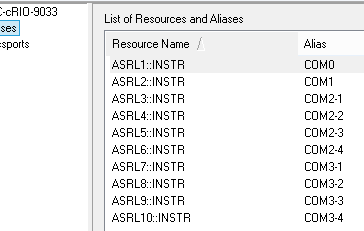
I have a cRIO OR 9033 with two RS232 9870 cards. The two cards series and their ports do not appear when I turn on the cRIO. When I run my executable in real time, once it crashes, saying: he cannot find the ports I ask. After that it crashes, the channels appear in MAX and VISA resource controls, and when I run the program a second time, it works very well. Why does this happen? Is it possible that I can have the save of the series, so I don't need to have the program crash whenever the cRIO starts?
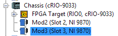
I run my program in hybrid mode. I Interface FPGA and including two maps cRIO outside the FPGA target, like this:
I tried the cancellation of the deployment and the deployment of all, but it does not help. It blocks the first time regardless if I execute the suite of LabVIEW Development or if I deploy it as an RT executable and run at startup.
Here are some pictures of what is happening:
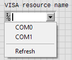
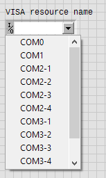
10-port VISA should be available. The two on the chassis and four for each card to 9870.
When I start first cRIO, only the ports of two chassis looks for selection in a control channel VISA:
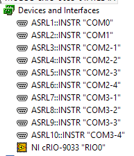
And the channels do not arise to the MAX:
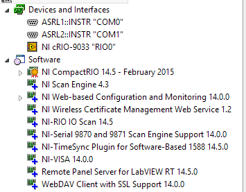
Showing also currently installed software.
When I go to the settings of NI-VISA 14.0.0 page I see this:
Channels appear here, but nowhere else.
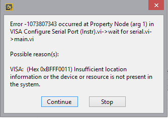
When I try to run my program, I get this error:
And after the error, the channels appear in LabVIEW and MAX!
Series settings will remain as long as I leave the cRIO powered. If I disable, settings series pannals and I need run my program once only it crash before I can use the serial ports.
I would really like for these settings apply automatically without having it fail the first time.
Any suggestions?
I also run hybrid FPGA on cRIO with cards 9870 and 9871 under the scanning engine you are. I also noticed behaviour buggy when accessing the COM ports - for example, if the cRIO running the executable version of his program and you interrupt it to run the same program in interactive mode, often, you receive the error message "missing resources VISA." So what I do is restart the cRIO with the disabled startup application.
I honestly would not bother to configure anything through MAX when it comes to your cRIO. You configure port configuration programmatically. In the process of initialization of your program, open your bitfile, run it, wait, a few seconds to have everything settle, make a VISA "find resources" and confirm all your ports appear, then use the VISA to configure and open the port by program. This way worked for me.
Maybe you are looking for
-
Voive Memo app does not start upon transfer to the new phone
I transferred the contents of an iPhone 4 to iPhone 4 (32 GB, iOS 9.3.2) Asia via iTunes on my PC. Everything else seems to work OK, but when I try to run the voice memo application a window opens with the heading "Cannot create voice memo" and stati
-
Satellite C870-196 - Long launch after BIOS update
Hello I went to your BIOS 6.00 6.70 and I have a very long black screen between the TOSHIBA logo and the launch of my session, I had not before! I put the default settings in the BIOS (F9) as shown. Where can you what happened and what to do? Thank y
-
Photosmart 6520 all-in-ine: printer not found
Unit leaves impression of everything wireless. Checked printer and it says connected. Reinstalled the software put in the IP of the printer. Still not recognized. Turned off the printer and back. Same setup wizard on printer. Device has been printing
-
'Share' button overview broken after update?
I just applied the new security update and the 'share' Preview button no longer works. Does anyone have an idea how to solve this problem? Thank you!
-
I want to set the password for the screen saver to something else that the network password that I use. Is this possible in Windows 7?