RTSI sample clock source
Hello
I have a small question on an example of clock by RTSI source.
In my configuration, two PCI cards (PCI-6602 (dev2) and PCI-6110 (dev1)) are connected by a RTSI cable.
I would like to build a clock on 6110 source sample and use it on 6602 counting external impulses of entry.
In the MAX test Panel, I checked that a meter was reading of external signals.
However, the vi attached do not work, and the whole County, and then give an error of 200284.
Could you tell me what is the problem?
I guess that something is not right on the clock signal routing. I have to use DAXmx connect terminals vi instead of external signal?
How can I check that both devices are connected through a RTSI cable?
I recorded the cable and connected devices on MAX with no problems. Is this enough?
Thank you for your comments and kind suggesion.
Several things briefly:
- Must match the orientation of the RTSI cable. Connectors are generally indexed to ensure this, but if you use a cable in water House, just keep it flat between the boards.
- The code you posted attempts to use the time base internal 20 MHz as a sample clock. That will not work for several reasons, and the fact that you try suggests you may have a poor understanding of the functioning of the meter. You do * not * need to "sample" at a pace high in order to catch the digital transitions. The meter circuit manages everything in the material. What you "sample" in a task of counter is a County registry value. Digital TTL edges which are worth little matter how many times you "sample" it increases.
- I suspect you want to * account * cycles of the clock of the signal of your 6110, be it a train of pulses counter or a sample clock based on the tasks.
- I am writing an example that does without buffer sampling clocked by the software, to approximately 10 Hz. Dev2 uses to generate a pulse of 1000 Hz and uses Dev1 train to interrogate the County registry value in a loop. It is simple from the code you posted to help unravel the special problems of routing RTSI config problems. Start using something simple like this to see if DAQmx succeeds routing signals through RTSI.
-Kevin P
Tags: NI Hardware
Similar Questions
-
Requested sample clock source is invalid wls-9163
My goal is to use two accelerometers that using the NI 9234 entry of the modules and wireless wls-9163 chassis.
My program is attached. Here is a photo in case you do not want to download the attachment: http://www.imagebam.com/image/577a4a195651371.
The slave device is not able to use the sample clock that came out of the master on PFI1.
I looked through the wireless DAQ resource kit and watched the following video:http://www.YouTube.com/watch?v=g_8jiKuKeDI
and ive read this: http://zone.ni.com/devzone/cda/epd/p/id/6124
I am aware that
I also tried to synchronize two cDAQ-9178 using the same methods. I always get the error "required sample clock source is not valid.
The manual says it should be able to do this
http://www.NI.com/PDF/manuals/372488c.PDF
Any help would be greatly appreciated.
Vexis,
Unfortunately, at the moment, you cannot synchronize the modules that use adelta-sigma converter (such as the NI 9234) in several cDAQ chassis. This is because these modules use a clock of sampling, which is very high; the PFI lines are unable to return to the required sample clock. You can share the start triggers, but the clocks of individual modules will drift over time.
The reason that the error message says that "requested the sample clock source is not valid" is because these modules require the use of a sample of clock that comes inside a time base clock oversampling.
Sorry for the bad news!
Katie
-
None of RNS, te0 & te1 clock source work except OnbordClock for cDAQ9174?
acquisition system used: cDAQ-9174, NI9206, Labview2009, OR-DAQmx 9.2, MAX 4.7.1
Referring to the "specifying different sample rates for CompactDAQ Modules multiple", following time engines could be used for cDAQ9174 (AI, te0 & te1)
/ cDAQ1/I/SampleClock
/ cDAQ1/TE0/SampleClock
/ cDAQ1/TE1/SampleClock
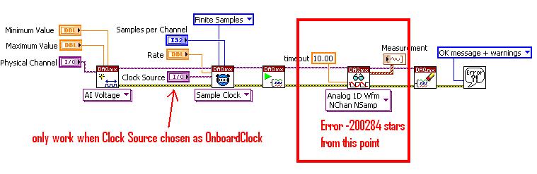
However, for the voltage-Clk attached Acq Select.vi, none of the above clock works unless OnbordClock is selected. Can someone explain this please?
Hi NCLbingji,
'Source' entry "DAQmx Timing (sample clock) .vi" tells DAQmx to get the sample clock a PFI PIN or another subsystem (such as AO, DIO or counters). It has not been designed to choose what sync engine to use. I think that the example of the community that you mentioned is defining the sample clock source incorrectly.
On a device with a single timing engine of HAVE, like cDAQ-9172, ' IA/SampleClock' by specifying the source of the sample clock I tells DAQmx to deliver the sample clock GOT to the sample clock, which he cannot do it, then it gives you a more useful error:
"Error-89131 occurred in DAQmx start Task.vi:8 '.
Possible reasons:
Attempted to perform an itinerary when the source and destination are the same terminal.
In many cases, like when you configure an external clock or counter source, you must select a PFI, PXI or RTSI trigger line as the terminal of the source.
Property: SampClk.Src
Property: SampClk.ActiveEdge
Source device: Dev1
"Terminal source: AI/SampleClock.A cDAQ-9174, DAQmx chooses the timing engine when you book the job. The timing engine he chooses does not necessarily match the timing engine that you specify in the VI. If it does not match (for example your VI specifies te1/SampleClock, but DAQmx choose te0), then your task will wait for Terminal produce some clock pulses. Because there, there is no clock on this terminal, the task eventually times out and returns the error-200284 (samples not yet available).
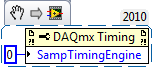
The correct way to explicitly specify what sync engine to use is to set the SampTimingEngine property.
Unfortunately, the table of values for this property by using NOR-DAQmx for 9.2.x version is also incorrect (reported to R & D such as CAR #239502). Here are the correct values:
- 0 selects te0.
- 1 selects te1.
- 2 selects HERE.
You can also leave DAQmx choose a timing engine, then ask that you chose. To do this, choose the task and then get the value of the SampClk.Term property.
Brad
-
An external sample clock between sharing arrangements
I need to acquire samples of 2 separated Renault M series (PCI-6254). My master device receives a sample of 8 on PFI0 KHz clock. Is it possible at the root of this clock of the master to the slave via a RTSI cable device?
I looked through the forum and the sample programs, but have only seen examples in which the master clock on board the aircraft happened to the slave.
It is possibe to synchornize device slave the master clock to external sampling of the device?
Thank you
ANT1
ANT1,
Fortunately, most of the time something that can be done in DAQmx in LabVIEW can be done in ANSI C using the appropriate function calls. I have listed the following steps of the program example LabVIEW and retouched to remove anything that it is not suitable for the DAQmx configuration. I'm sure it should work for you.
Steps to follow:
1 create a channel of analog input voltage for the master and the slave.
2 set the synchronization parameters. For the master, select the source of the external sample clock. Set the source AI/SampleClock of the master for the slave device. (Note: sample of the master clock is automatically routed through the cable RTSI.)
3. for the slave, set the Source of the trigger to the AI/StartTrigger of the master device. This will ensure that both devices start sampling at the same time. (Note: the trigger is automatically redirected via the RTSI cable.)
4. call the start task to start the acquisition. (Note: start slave task before the master task.)
6. read all waveform data.
7. call the clear task to stop the acquisition and clear the task.So, essentially, the value of the task of the slave to the top in the same way as you would for the synchronization of clocks on board, but configure the task to master as you would for an external clock. This will automatically share the external clock and trigger on the line of the RTSI.
-
Synchronization of analog and digital output with the external sample clock
Hello
First of all sorry for my English, I will try to explain what I want to do.
I want my PCIe-6321 to send two custom signals (modification sawtooths) on a mirror controller. I would also like to generate output with my card at the beginning of each tooth of saw. Everything must be synchronized with an external k-clock signal of 100 kHz. The idea is that whenever the PCI receives a trigger to external clock, it sends two analog output voltages and when he received 1024 clock ticks it will also send a pic of triggering TTL. What I do is first prepare the map and after that in a loop sending and modifing the output values of the two signals and at the same time send a digital signal Boolean in each arch, so when's done it 1024 iterations of the loop I send an event to the digital port. Attached you can see.
The problem is that I don't know how to synchronize both. Can I use the sample clock just to the analog output? I can use sample for the two outputs clock, or do I need to use the output of the meter? If don't know how to use it here.
If I do nothing else bad/wrong, I would be grateful for feedback.
Thanks in advance,
PabloI don't know how but I find the solution. I'm generating more than a positive value (as I was triggered maybe very fast the oscilloscope has been absent there). If I put the sample clock of digital output to use the sampling/ao/Dev1 clock that it doesn't, but if I put to use the same source as the OD (terminal where my external clock is connected), but the trigger to start the DO to be Dev1/ao/StartTrigger this works. I don't really know why, but it does.
Thank you for your patience and your help. I put here the final code.
-
External sample clock change takes a lot of time on the SMU-5186
Hello
I use the external Lv - niScope EX Clocking.vi example to define SMU-5186 using an external sample clock. However, it takes a long time, 5-6 minutes, before I can get the first block of data acquisition.
Then I run the example 'niScope EX Acquisition.vi Configured' to switch to dashboard clock. There are also 5 to 6 minutes on the first acquisition.
I think maybe the SMU-5186 made some calibration when I change the source of the clock.
Anyway is to ignore the calibration? Or make it faster?
Thank you very much
Yiming
Yiming,
Delays in acquisition are caused by calibration routines that must be performed on the engine to sample (ADC) every time that changes sampling rate. This ensures our justified precision specifications.
I don't know if you've noticed also calibration of Power-Up, which will take 5-10 minutes to complete when the unit is turned on. This is mentioned in our specifications at page 18:
http://www.NI.com/PDF/manuals/373257b.PDF#page=18
I hope this helps.
Nathan
-
divide the internal sample clock (VCXO)
Hi all
I want to divide clock source internal sample of my high-speed 5122 digitizer PXI card.
5122 PXI, 200 MHz internal clcok source example. I want to taste my data at 10 MHz.
So I want to divide down the clock of internal sampling by a factor of 20.
I want to do it programmatically.
I have found no vi node or property for that (although found the node property for entry divider OR worn... but which has been used only for reference for on-board clock clock)
Help me as soon as possible...
Hi Jirav,
I just wanted to clear some things. The 5122 has a sampling rate 100 MECH's maximum real-time. / s (not 200 MHz as you originally suggested). To obtain a rate of 10 MHz, you would be divided down by a factor of 10. From page 13 of the document specifications NI 5122:
Just to add to what Henrik suggested, the following help topic describes the specific VI to configure horizontal properties such as the sampling frequency, he mentioned:
http://zone.NI.com/reference/en-XX/help/370592P-01/scopeviref/niscope_configure_horizontal_timing/
Most of the expedition OR SCOPE examples use the VI above and there is an entry for "min sampling rate" where you can simply specify the value "10 M" or '10000000' to get the device of sampling at a lower rate.
Note: because the digitizer allows only sampling frequencies which are an integer divide down the maximum sampling frequency, rate will always be forced to match up to the second tier legal sample. For example, if you specify '9.8435 M', it would automatically force the rate up to 10 MHz. To display the actual value that the scanner is used, you can query the property node "Actual sampling frequency" at any point in your code after the configurations have been committed digitizer. The help manual describes this property on the following page:
http://zone.NI.com/reference/en-XX/help/370592N-01/scopepropref/pniscope_actualsamplerate/
Kind regards
-
sample clock adjust external trigger
I am trying to use a source of external trigger non - TTL (square wave ~ 8 kHz from 0 to 1.4 V instead of 0 to 5 V) as the clock for an analogue waveform output voltage. Is there a way I can manually change the threshold used for the clock source so that I can get this working?
I'm trying to avoid having to solve this problem at the hardware level, which in my opinion, is to build a comparator circuit to generate a trigger signal TTL of my 0-1, 4 a signal trigger V square.
If not, is there a way I can generate a TTL signal that is synched to my trigger signal 0 to1.4 V ~ 8 kHz wave square using these maps NOR: PCI-6115 or PCIe-6323?
Thank you!
Cecinix, you are right. The sample of the signals clock are specified to be TTL signals, which means that the minimum thresholds of high voltage on the PCI-6115 and PCIe-6323 are respectively 2.2 V and 2,0 V. Digital/PFI input thresholds are listed in the data sheets of the devices, so that they are material defined. Unfortunately, given that all the digital inputs on the card you mention expect tensions TTL, it's something that you have to fix in the material. A comparator circuit could operate as a network of transistors of pull-up.
What generates the square wave? Would it not viable for generating a signal of TTL clock on your NI DAQ card and export this signal to the rest of your system? In general, a digital system is quite tolerant of extra tension a bit, so it's maybe easier than adding voltage conversion circuits.
Kind regards
William R.
Technical sales engineer
-
I use an analog input on a PCI-6224 and are having problems with the clock source
I use an analog input on a PCI-6224 and are having problems with the clock source. I'm trying samples of 16 different analog inputs very quickly. I have the sample mode: Timed Single Point material. The rate, that I am running is the maximum (250 kHz (15625Hz per channel)). I left the default clock source and trying to taste several times. The analogue input works for a short time (2-3 seconds) and then everything stops. I'm doing something wrong or is there something I'm missing? Any advice would be great.
That's how you samples using the sample clock clock. If you see a delay then something is wrong with how you track/data visualization.
Single point NI the hardware is for PID control with a real-time operating system.
-
FPGA and external clock Source
By using a PXI-7854R, is it possible to run a process on an external clock source? As far as I know, you could potentially bringing the external clock to one of the triggering RTSI lines. Is this correct? Is it possible to route through one of the connectors on the PXI-7854R? If this isn't the case, I also have a PXI-6229. Can the external clock be routed to the RTSI through the PXI-6229 and then line for the PXI-7854R to run the process?
Hello
Unfortunately not, as noted hereand here. The best solution is just the external clock with DIO on a structure of case to door. While this will not have any type of phase synchronization and you may miss the clock cycles depending on how long and how fast your external clock is running (not really an option). I hope that answers your question.
-
sample clock 6551 exporting to PXI_STAR
Hello
The help files for the x 655 (devices-> NI 655 x-> hardware-> Signal Routing Architecture) is a chart that shows the 6551 as source's internal sample clock and the PXI_STAR as a destination. I tried to implement, but it is back with a runtime error stating that the material doesn't have this ability. I have the 6551 in slot 2 the PXI backplane. Am I misunderstood the routing table in the help file.
Part of the code...
Configure the internal clock generator to be Meg 2
ErrChk (niHSDIO_ConfigureSampleClock (* viGen [out_card_number], NIHSDIO_VAL_ON_BOARD_CLOCK_STR, 2.0e6));
export the sample clock on co - ax signal clock
ErrChk (niHSDIO_ExportSignal (* viGen [out_card_number], NIHSDIO_VAL_SAMPLE_CLOCK, VI_NULL, NIHSDIO_VAL_PXI_STAR_STR));
make a commit to start the clock output
ErrChk (niHSDIO_CommitDynamic(*viGen[out_card_number]));Thank you
Andrew
Hello Andrew,.
The documentation is in fact inaccurate. Only certain devices can actually lead the line PXI_STAR as destination and 655 x devices cannot. It was a mistake in our documentation and has been reported to R & D under ID #166056. I believe that the following devices can lead the line slot of two PXI_Star:
- PXI-4461
- PXI-4462
- PXI-4472
- PXI-4472 b
- PXI-4474
- PXI-5112
- PXI-7344
- PXI-665 x
- PXI-6682
Please let me know if you want to use one of these devices and we can have a person from their product group check that they will be able to lead the line PXI_Star.
Kind regards
Paul C. -
Measurement error of the County of edge by using the external sample clock
Hello
I'm trying to measure the number of edges (rising) on a square wave at 5 kHz with a generator function on a device of the NI PCIe-6363. I configured a channel of County of front edge of counter at the entrance of the PFI8 device. I use an external sample clock that is provided by the output of the meter of a NI USB-6211 housing channel. If I acquire for 10secs then ideally I would expect to see a total of 50000 edges measured on the meter inlet channel. However, my reading is anywhere between 49900 and 50000.
When I use the internal clock of time base to measure the edges, the measure is accurate and almost always exactly 50000. I understand that when you use the external sample clock, the precision of the measurements is subject to noise level of the clock signal. However, I checked the clock signal is stable and not very noisy. Any reason why there is an error of measurement and how tolerance should I expect when using an external sample clock compared to when you use the internal time base clock?
Also, what is best clock Frequency (with respect to the frequency of the input signal) when using an external clock?
Thank you
Noblet
Hi all
Thanks for all your sugggestions. I was using an input signal with a function generator which had a range of 8V. It turns out that the reduction of the amplitude to 5V solves the problem. I was able to get accurate numbers with the 6211 external clock.
Thank you
Noblet
-
AI sample clock using to Trigger counter samples
My basic question is: the ai\SampleClock signal is active only during the execution of a task of analog input?
The details are:
I have a multifunction data acquisition card series X PCIe-6321. It is controlling an SCXI chassis and has a module SCXI-1180 and SCXI-1302, so I can control the analog inputs of the chassis but also access to the meter 4 on the map. My application requires that I use all 4 meters to measure a frequency input signal and synchronize the samples for the analog input signals. I created 5 tasks, 1 for AI and 1 for each counter.
I'm using LabVIEW 8.6.1 with the latest NOR-DAQ drivers on and the operating system 64-bit Vista
1 are there drivers or hardware restrictions that cause this solution does not work?
2. can I use the ai\SampleClock as sample clock of entry for each task frequency? If I do this the beginning of sampling will be synchronized? I.e. If I each task frequency first starts, they will wait until that task to HAVE it is started before you start sampling?
3. If this does not work, do I need to send the sample clock of the task of the AI to a line PFI (PFI1) and then use it as the special frequency sample clock input?
I used to do option 3 when the synchronization of two cards in PXI chassis and use only the beginning of the task of the software instead of synchronization on a digital departure, given that the sample clock will control samples anyway. I need to know if the same behavior works with the above scenario.
Thank you
Bob
Prolucid Technolgies Inc.
Hi Bob,
I can confirm that the AI/SampleClock is available only during the execution of the task to HAVE it. As far as other issues go:
1. you must provide more information on what you seek to do exactly, but there is no problem with the clock of the task of analog input sampling to be used with routing counters. I had read through the section of the X series operating manual which deals with the measures of frequency clocked at sample (see page 7-16) for more information about what really happens during this configuration to make sure that it suits your needs.
The frequency of the signal to be measured must be at least two times faster than the sample of your task clock to HAVE.
2. you can indeed pass the signal on all four tasks at the same time (you can check the page peripheral routes in MAX to ensure the routing restrictions). Sampling will be synchronized four counters are started before the task to HAVE it, but counters will be armed at different times unless you configure a trigger to begin arms (see page 7-45 series X operating instructions). I would consider using the AI/StartTrigger if you want to do.
The effect of not to arm the counters at the same time would be a different number of periods on average on each counter for the first sample (assuming an average is enabled). Maybe it's not a major concern, but I just wanted to point out.
3. the itineraries are available inside the Board of directors so external routing is not necessary, you can simply specify to use the sample clock of the AI for each meter clock and roads will be done for you. If you want to export the signal on a PFI line and new route on another line PFI, this option is also available for you, but shouldn't be necessary.
I hope this helps you get started. I'll make sure to take a look at Chapter 7 of the X series user manual, if you have a chance as he described how all configurations of meter of working more in detail. If you have related questions do not hesitate to post in return.
Best regards
John
-
Problem with DAQmx Schedule VI (sample clock)
Hello to you all,.
I'm new to this forum, please bare with me. I have some experience with LV, but I am relatively new to data acquisition projects. I use LV2009.
I want to make sure that I use the hardware timing (instead of software distribution) in my project so I followed some of the threads here as sugested to use DAQmx Schedule VI. The problem is that no matter how I set the system I get the same error-200300 invalid calendar
type.The project is simple. I encode with 1000 pulses per
Rev and it is mounted on a shaft of a turbine water goes thru. I'm watching the frequency
and so the rotation of the shaft which tells me that the amount of water flows through the turbine. In the end, there will be 2 channels
by every encoder and ~ 3 encoders (turbines) total and calibrated the main meter that will give me constant impulses and all encoders will be compared to this master frequency.I'll use PCI6602 DAQ, but
now, for the development, I use USB6221. Let's say that the
frequency is between 500 Hz and 10 kHz. What I am doing wrong? Or maybe better to ask - what would be the right approach for this project?Thank you
Marty
Hi Marty,
It seems that your question is already answered here, but Jason is correct that the 6221 neither the 6602 support a clock sampling for frequency measurements.
As Jason mentioned, your best bet is also likely set the mode of synchronization for "implied". This means that the frequency value is sampled at the end of each period of your input signal. In addition, a solution that is clocked by the software (On-Demand) might be acceptable.
X Series DAQ devices allow an external sample clock to use for frequency measures (described in the Manual of X series). Frequency of sample-clocked measures are useful in very specific
circumstances, but it does not seem that you need this feature based on what you've described so far.(621 x) bus-powered M series can also be configured to use an external sample as the X series clock but do you not have the same features described in the manual of the X series.
I hope this helps!
-John
-
Buffer the output AO, refresh rate is different from the sample clock frequency
Hello
I am an AO output in the buffer using a single channel. I have a stamp with a ripple of 200000 points with a triangular waves of a 1000pts each repeated 200 times. If I want a frequency of 1 Hz, I simply update this waveform 1000pts and if I wanted to 5 Hz, then 5000pts and so on. But there is some frequency that I won't be able to use like the refresh rate (the number of samples that I ask to update) is different from the sample clock frequency, which makes synchronization with the other difficult to trigger (incomplete cycle). Frequency 3 Hz (update 3000pts), as (update 7000pts) 7, 6 Hz (update 6000pts), 9 (update 9000pts)... 11Hz at 15 Hz and is not valid in the sense that the refresh rate is different from the sample clock frequency. That makes a whole lot of inaccessible CONFIGURED! Can someone tell me what determines the banned frequency? Is this something to do with the material?
concerning
One thing you can try is to change the number of samples per cycle. This cannot give the precise frequency accurately, but can reduce the average error.
120 Hz, the error is currently about 400 parts per million (ppm). The accuracy of the time base is 50 ppm, then this error is less than 10 times the inherent error due to the time base.
Consider this configuration: the closest nominal sampling you rate, you can get is 120048 Hz (1000 samples per cycle at 120 Hz). If your buffer contains 1200 samples per cycle, 100 copies of it would produce 1 second of data to 120,048 Hz. But if the buffer contained an average of 1200,48 useful Samper by cycle, you get the exact frequency. Of course getting 0.48 of a sample is delicate. But the kind of feasible. If you use 48 cycles in the 1201 samples per cycle and the cycles of 52 to 1,200 samples per cycle, the total number of samples per second = 120048. Average frequency will be exactly what you want. Instantly, the frequency is slightly higher or lower than the exact value. By an alternation of 1200, 1201, 1200, 1201... 1201, 1200 100 cycles that the Jig is fast. If you group all 1200s whole and all 1201 s frequency hopping may be more sensitive. If this kind of jitter is acceptable depends strongly on what you do with the release.
This technique is used in some systems of frequency synthesizer.
Lynn

Maybe you are looking for
-
iPad will not slide to open or close
Mini iPad will not slide to open or close.
-
How to recover deleted history?
I accidentally deleted all of my history, and I want it back. I'm on mac, if that helps. Please help because it's really annoying because I lost all my favorites and everything. Thank you.
-
New user meticulous Thinkpad T440S, coming from a Samsung NP 700
Old NP 700 series. Beautiful samsung keyboard and touchpad: http://images.amazon.com/images/G/01/electronics/samsung/samsung-12q2bts-series7-15-keyboard-lg.jpg 1. What is precdedence in power options: power of bios options (max perf / etc) vs vs leno
-
I run my T420 on a docking station. Basically, I want to use the laptop screen and two separate screens. Is this possible? I tried, but it doesn't seem to detect one of the screens.
-
OKI B6100 Laser / Win7-64 driver?
HYA!-Compatibility Center MS told me, that the OKI B6100 (N/PS) Mono Laser printer should be compatible with Windows 7/64. Literally: "this product installs automatically without extra software." Briefly: Yes * No. * MS Compatibility Center must be