sample clock adjust external trigger
I am trying to use a source of external trigger non - TTL (square wave ~ 8 kHz from 0 to 1.4 V instead of 0 to 5 V) as the clock for an analogue waveform output voltage. Is there a way I can manually change the threshold used for the clock source so that I can get this working?
I'm trying to avoid having to solve this problem at the hardware level, which in my opinion, is to build a comparator circuit to generate a trigger signal TTL of my 0-1, 4 a signal trigger V square.
If not, is there a way I can generate a TTL signal that is synched to my trigger signal 0 to1.4 V ~ 8 kHz wave square using these maps NOR: PCI-6115 or PCIe-6323?
Thank you!
Cecinix, you are right. The sample of the signals clock are specified to be TTL signals, which means that the minimum thresholds of high voltage on the PCI-6115 and PCIe-6323 are respectively 2.2 V and 2,0 V. Digital/PFI input thresholds are listed in the data sheets of the devices, so that they are material defined. Unfortunately, given that all the digital inputs on the card you mention expect tensions TTL, it's something that you have to fix in the material. A comparator circuit could operate as a network of transistors of pull-up.
What generates the square wave? Would it not viable for generating a signal of TTL clock on your NI DAQ card and export this signal to the rest of your system? In general, a digital system is quite tolerant of extra tension a bit, so it's maybe easier than adding voltage conversion circuits.
Kind regards
William R.
Technical sales engineer
Tags: NI Software
Similar Questions
-
AI sample clock using to Trigger counter samples
My basic question is: the ai\SampleClock signal is active only during the execution of a task of analog input?
The details are:
I have a multifunction data acquisition card series X PCIe-6321. It is controlling an SCXI chassis and has a module SCXI-1180 and SCXI-1302, so I can control the analog inputs of the chassis but also access to the meter 4 on the map. My application requires that I use all 4 meters to measure a frequency input signal and synchronize the samples for the analog input signals. I created 5 tasks, 1 for AI and 1 for each counter.
I'm using LabVIEW 8.6.1 with the latest NOR-DAQ drivers on and the operating system 64-bit Vista
1 are there drivers or hardware restrictions that cause this solution does not work?
2. can I use the ai\SampleClock as sample clock of entry for each task frequency? If I do this the beginning of sampling will be synchronized? I.e. If I each task frequency first starts, they will wait until that task to HAVE it is started before you start sampling?
3. If this does not work, do I need to send the sample clock of the task of the AI to a line PFI (PFI1) and then use it as the special frequency sample clock input?
I used to do option 3 when the synchronization of two cards in PXI chassis and use only the beginning of the task of the software instead of synchronization on a digital departure, given that the sample clock will control samples anyway. I need to know if the same behavior works with the above scenario.
Thank you
Bob
Prolucid Technolgies Inc.
Hi Bob,
I can confirm that the AI/SampleClock is available only during the execution of the task to HAVE it. As far as other issues go:
1. you must provide more information on what you seek to do exactly, but there is no problem with the clock of the task of analog input sampling to be used with routing counters. I had read through the section of the X series operating manual which deals with the measures of frequency clocked at sample (see page 7-16) for more information about what really happens during this configuration to make sure that it suits your needs.
The frequency of the signal to be measured must be at least two times faster than the sample of your task clock to HAVE.
2. you can indeed pass the signal on all four tasks at the same time (you can check the page peripheral routes in MAX to ensure the routing restrictions). Sampling will be synchronized four counters are started before the task to HAVE it, but counters will be armed at different times unless you configure a trigger to begin arms (see page 7-45 series X operating instructions). I would consider using the AI/StartTrigger if you want to do.
The effect of not to arm the counters at the same time would be a different number of periods on average on each counter for the first sample (assuming an average is enabled). Maybe it's not a major concern, but I just wanted to point out.
3. the itineraries are available inside the Board of directors so external routing is not necessary, you can simply specify to use the sample clock of the AI for each meter clock and roads will be done for you. If you want to export the signal on a PFI line and new route on another line PFI, this option is also available for you, but shouldn't be necessary.
I hope this helps you get started. I'll make sure to take a look at Chapter 7 of the X series user manual, if you have a chance as he described how all configurations of meter of working more in detail. If you have related questions do not hesitate to post in return.
Best regards
John
-
Synchronization of analog and digital output with the external sample clock
Hello
First of all sorry for my English, I will try to explain what I want to do.
I want my PCIe-6321 to send two custom signals (modification sawtooths) on a mirror controller. I would also like to generate output with my card at the beginning of each tooth of saw. Everything must be synchronized with an external k-clock signal of 100 kHz. The idea is that whenever the PCI receives a trigger to external clock, it sends two analog output voltages and when he received 1024 clock ticks it will also send a pic of triggering TTL. What I do is first prepare the map and after that in a loop sending and modifing the output values of the two signals and at the same time send a digital signal Boolean in each arch, so when's done it 1024 iterations of the loop I send an event to the digital port. Attached you can see.
The problem is that I don't know how to synchronize both. Can I use the sample clock just to the analog output? I can use sample for the two outputs clock, or do I need to use the output of the meter? If don't know how to use it here.
If I do nothing else bad/wrong, I would be grateful for feedback.
Thanks in advance,
PabloI don't know how but I find the solution. I'm generating more than a positive value (as I was triggered maybe very fast the oscilloscope has been absent there). If I put the sample clock of digital output to use the sampling/ao/Dev1 clock that it doesn't, but if I put to use the same source as the OD (terminal where my external clock is connected), but the trigger to start the DO to be Dev1/ao/StartTrigger this works. I don't really know why, but it does.
Thank you for your patience and your help. I put here the final code.
-
Clock and hw external trigger with USB-6210 on Linux with NOR-DAQmx Base?
I have two devices USB-6210 I need to synchronize so that they both collect data exactly at the same time. I was told by support OR I can send the clock off Dev1/PFI4 and have the two USB-6210 s read the clock in through their own PFI0. I also want to trigger data collected for each device by sending a trigger off Dev1/PFI6 and have two devices to receive the signal on PFI2.
All my attempts to try this are filled with error messages and my research online seem to say that's not possible with USB devices on NOR-DAQmx Base 3.4.0f2 on Linux.
I "ve tried using example AI programs and those who do not seem to work either for external clocks. Here is the code I tried:
#include "NIDAQmxBase.h"#include

#define DAQmxErrChk(functionCall) { if( DAQmxFailed(error=(functionCall)) ) { goto Error; } }

int main(void){    // Task parameters    int32       error = 0;    TaskHandle  taskHandle = 0;    char        errBuff[2048]={'\0'};    int32       i;

    // Channel parameters    char        chan[] = "Dev1/ai0";    float64     min = -10.0;    float64     max = 10.0;

    // Timing parameters    char        clockSource[] = "/Dev1/PFI7";    uInt64      samplesPerChan = 1000;    float64     sampleRate = 10000.0;

    // Data read parameters    #define     bufferSize (uInt32)1000    float64     data[bufferSize];    int32       pointsToRead = bufferSize;    int32       pointsRead;    float64     timeout = 10.0;

printf("Calling CreateTask...\n");    DAQmxErrChk (DAQmxBaseCreateTask("",&taskHandle));printf("Calling CreateAIVoltageChan...\n");    DAQmxErrChk (DAQmxBaseCreateAIVoltageChan(taskHandle,chan,"",DAQmx_Val_Cfg_Default,min,max,DAQmx_Val_Volts,NULL));printf("Calling CfgSampleClkTiming...\n");    DAQmxErrChk (DAQmxBaseCfgSampClkTiming(taskHandle,clockSource,sampleRate,DAQmx_Val_Rising,DAQmx_Val_FiniteSamps,samplesPerChan));printf("Calling StartTask...\n");    DAQmxErrChk (DAQmxBaseStartTask(taskHandle));printf("Calling ReadAnalogF64\n");    DAQmxErrChk (DAQmxBaseReadAnalogF64(taskHandle,pointsToRead,timeout,DAQmx_Val_GroupByChannel,data,bufferSize,&pointsRead,NULL));

    printf ("Acquired %d samples\n", pointsRead);

    // Just print out the first 10 points    for (i = 0; i < 10; ++i)        printf ("data[%d] = %f\n", i, data[i]);

Error:    if( DAQmxFailed(error) )        DAQmxBaseGetExtendedErrorInfo(errBuff,2048);    if(taskHandle != 0) {        DAQmxBaseStopTask (taskHandle);        DAQmxBaseClearTask (taskHandle);    }    if( DAQmxFailed(error) )       printf ("DAQmxBase Error %d: %s\n", error, errBuff);    return 0;}
When I run the resulting program, I see this:
$. / acquireNScans-ExtClk
The CreateTask call...
Call for CreateAIVoltageChan...
Call for CfgSampleClkTiming...
Error-89136 DAQmxBase:route specified cannot be satisfied, because the hardware does not support it. For example, a clock and a trigger can be imported via one of the PFI lines by using a USB-6210 on Linux with NOR-DAQmx Base? A clock and a trigger exportable via one of the PFI lines?
If so, does anyone have the code example illustrating how to do this, or can you at least tell me the names of the lines ("PFI0/Dev1" or other) so I can try again?
Clues or suggestions would be helpful.
Thank you
-Tom
The clockSource in the example specifies an output rather than an input channel channel. Change source "/ Dev1 / PFI0" solved the problem.
Please close this post.
-
An external sample clock between sharing arrangements
I need to acquire samples of 2 separated Renault M series (PCI-6254). My master device receives a sample of 8 on PFI0 KHz clock. Is it possible at the root of this clock of the master to the slave via a RTSI cable device?
I looked through the forum and the sample programs, but have only seen examples in which the master clock on board the aircraft happened to the slave.
It is possibe to synchornize device slave the master clock to external sampling of the device?
Thank you
ANT1
ANT1,
Fortunately, most of the time something that can be done in DAQmx in LabVIEW can be done in ANSI C using the appropriate function calls. I have listed the following steps of the program example LabVIEW and retouched to remove anything that it is not suitable for the DAQmx configuration. I'm sure it should work for you.
Steps to follow:
1 create a channel of analog input voltage for the master and the slave.
2 set the synchronization parameters. For the master, select the source of the external sample clock. Set the source AI/SampleClock of the master for the slave device. (Note: sample of the master clock is automatically routed through the cable RTSI.)
3. for the slave, set the Source of the trigger to the AI/StartTrigger of the master device. This will ensure that both devices start sampling at the same time. (Note: the trigger is automatically redirected via the RTSI cable.)
4. call the start task to start the acquisition. (Note: start slave task before the master task.)
6. read all waveform data.
7. call the clear task to stop the acquisition and clear the task.So, essentially, the value of the task of the slave to the top in the same way as you would for the synchronization of clocks on board, but configure the task to master as you would for an external clock. This will automatically share the external clock and trigger on the line of the RTSI.
-
Measurement error of the County of edge by using the external sample clock
Hello
I'm trying to measure the number of edges (rising) on a square wave at 5 kHz with a generator function on a device of the NI PCIe-6363. I configured a channel of County of front edge of counter at the entrance of the PFI8 device. I use an external sample clock that is provided by the output of the meter of a NI USB-6211 housing channel. If I acquire for 10secs then ideally I would expect to see a total of 50000 edges measured on the meter inlet channel. However, my reading is anywhere between 49900 and 50000.
When I use the internal clock of time base to measure the edges, the measure is accurate and almost always exactly 50000. I understand that when you use the external sample clock, the precision of the measurements is subject to noise level of the clock signal. However, I checked the clock signal is stable and not very noisy. Any reason why there is an error of measurement and how tolerance should I expect when using an external sample clock compared to when you use the internal time base clock?
Also, what is best clock Frequency (with respect to the frequency of the input signal) when using an external clock?
Thank you
Noblet
Hi all
Thanks for all your sugggestions. I was using an input signal with a function generator which had a range of 8V. It turns out that the reduction of the amplitude to 5V solves the problem. I was able to get accurate numbers with the 6211 external clock.
Thank you
Noblet
-
External sample clock change takes a lot of time on the SMU-5186
Hello
I use the external Lv - niScope EX Clocking.vi example to define SMU-5186 using an external sample clock. However, it takes a long time, 5-6 minutes, before I can get the first block of data acquisition.
Then I run the example 'niScope EX Acquisition.vi Configured' to switch to dashboard clock. There are also 5 to 6 minutes on the first acquisition.
I think maybe the SMU-5186 made some calibration when I change the source of the clock.
Anyway is to ignore the calibration? Or make it faster?
Thank you very much
Yiming
Yiming,
Delays in acquisition are caused by calibration routines that must be performed on the engine to sample (ADC) every time that changes sampling rate. This ensures our justified precision specifications.
I don't know if you've noticed also calibration of Power-Up, which will take 5-10 minutes to complete when the unit is turned on. This is mentioned in our specifications at page 18:
http://www.NI.com/PDF/manuals/373257b.PDF#page=18
I hope this helps.
Nathan
-
Looking for USB DAQ for AO using the external sample clock
Hi all
I'm looking for a cheap solution for the acquisition of data to select the AO using an external digital signal as sample clock, and I just realized that the USB-6001 is not a good candidate. Please someone remind the cheapest USB version for this task? There no need for high sampling rate. Thank you.
Define cheap and low sampling rate. You've already been told on the 6211.
-
NI6602 pulse width measurement: do I have to use an external sample clock?
Hello
In the example .NET 4 "MeasPulseWidthBuf_SmplClk_Cont", it is said in the comments that:
An external sample clock should be used.
Hi mola.
This specific example measures of sample-clocked pulse width. This type of measure is supported only on new hardware such as the X series cards and will not run on the 6602.
Your application that you have linked uses Implicit timing, which means that the signal is using the sample clock. In other words, at the end of each pulse duration which can be measured, the sample is deterministic locked in. So you end up with a table in the buffer of each pulse width which is seen by the meter.
Best regards
-
Generate a single pulse on several channels of an external trigger high-speed DIO
Hello
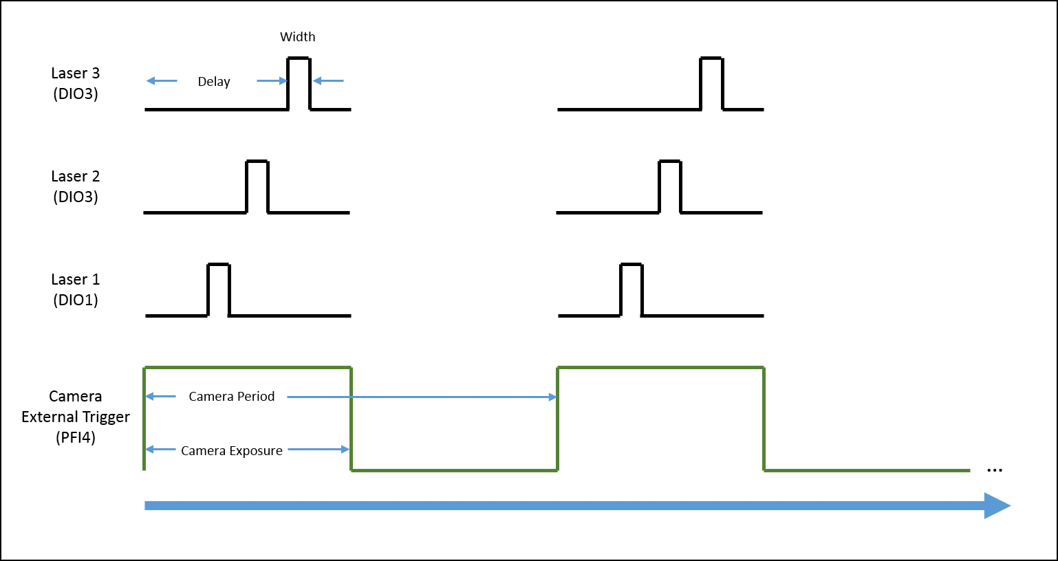
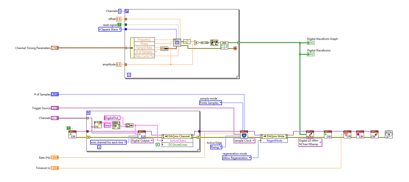
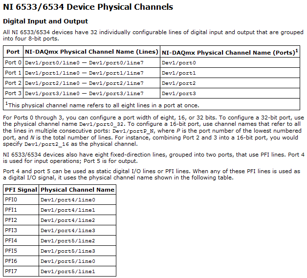
I'm trying to implement a system using a PCIe-6535 b connected to a high speed of SMB-2163 DIO. The system must be configured to work with a camera send a trigger (at the beginning of each show) to the PFI4 which in turn sends a single pulse on three digital output channels to lasers. Each output has its own specific deadline and the width. There is no counter on the SMB-2163, so I think I need to use Pulse Width Modulation (PWM). I saw this example and adapted to my system:
https://decibel.NI.com/content/docs/doc-8010
However, when the source to enter the DAQmx VI of sample clock is set to PFI4 (instead of the on-board clock) to receive input from the camera, changes in behaviour. The rate of sampling in the sample clock VI is ignored, and each element of the digital waveform is triggered. I need the sequence to complete each after trigger.
I am attaching a quick diagram of the sequence. Any suggestions on how I can get this kind of events triggered? (With the help of LabVIEW 2013)
Thank you
Mike
PLATES
The external signal must be configured as a trigger for digital startup rather than the sample clock. I do not think the 6535 redeclenchables supports digital output, so you don't have to restart the task after receipt of each trigger (something like this, however you can improve performance by committing to the task by using the task of control DAQmx before entering the loop).
Best regards
-
How the PFI to go top-to-bottom with sample clock?
Hello world!
I am very new to LabView and I try to do something very simple in the NI PCI-6534 and still not get anywhere (or do not know if it is the limitation of the hardware)
My request is to acquire digital data of 2 channels (16-bit each) of our Board custom designed analog-to-digital.
So far, I am in a position to acquire a finite amount of sampling digital (say 100000) and using a trigger to start (PFI6) to start the acquisition of our custom card board. Just to let you know that I'm feeding the PCI-6534 an external clock of 20 MHz by PFI2.
However, I want to send a signal to trigger recognition (high/low-rising edge) to our personal advice, saying: he did the acquisition of 100000-sample.
My problem is that whenever I try to use the lines of PFI signal with an internal sample clock, I get an error saying that I can't use the PFI lines with any sample clock. But my goal is to use a rising edge (low-high) to trigger back.
So far, I can pull the PFI4 high and used a timer to make it low. But the resolution of the timer is milliseconds (software) range. I would like to have at least a few microseconds.
I also tried using implicit since manual said that it does not require any clock but still get no result. Also, I couldn't find an example of implied clock and don't know if PCI-6534 supports.
Note that I'm able to use the clock synchronization of sampling with other DIO (Port 0 to Port 3) lines and get the result I want. However, I would need to use all our custom Board 32 - DIO for analog-to-digital data lines. So, using the line of PFI laccuse is the only choice.
If you have ideas/pointers, please throw it at me, I'll try them. Thanks a lot for your help!

See you soon,.
Yaseen KhanHi ykhan,
After validation, I noticed that it will not really work for what you are trying to do. The PFI lines on your 6534 are I/O static only as shown in the DAQmx help.
You will be able to control these lines, but only with software timing. You should be able to call and argue by their physical channel name. I hope this helps!
Kind regards
-
Hi all
I use a Board PXI-5422 generator of finished generation mode signals to generate an external trigger signal (PFI0) about every 5ms. There is a nominal 1.7µs delay of the input trigger for the start of the generation. That in itself isn't a problem (I can compensate for the delay), but there are up to 50ns jitter on this period, which is a problem. Does anyone know if there is anything I can do to minimize this jitter? (Incidentally, PFI1 exhibits the same behavior, but it is not a surprise)
Thank you very much
Hello GVR123,
I had a glance at the manual for the PXI-5422 and I found the note for the ' delay of start CH 0 analog output Trigger "which is indicated as"65 sample clock periods + 110 ns. With this information, I calculated that
1.7 - 0, 110 = 1.59
and
1.59/65=0.025 (bulk)
that points to a clock of 40 MHz. So I guess that's what you use.
25ns deviation (40 MHz) each side (50ns total), you see the expectation, as there is no way to ensure that the trigger falls exactly on a rising edge of the sample clock.
I hope this helps.
Kind regards
Michael S.
Technical sales engineer
NEITHER UK & Ireland -
Sync to external trigger in conjunction with a nearest pulse frequency device fixed...
I am writing an application running a scan frame. One axis of the scanner runs at a fixed frequency. I use a scanner high speed 5105 to get the data. The slow axis of the scanner is controlled by a servo with an analog input. I have will probably use an M-series card for analog control, but can also go with a 6713 (output only) or another Board. Fixed frequency Analyzer provides a clock line, I want to use to drive the 5105. In addition, the analog card must be synchronized in this. The entire system should be able to accept a trigger external devices, as it starts scanning at the edge of clock on next line.
I'm not quite sure about what would be the best way to do it. External triggering from other devices will be an indeterminate pulse width, so I can not just use it as a portal for the line clock. I am reluctant to do it in software (IE via the detection of changes on a digital line) because I want to be reliable started the next clock pulse. I have taken into account things like a counter/timer with a relaxing break, but which could lead to drift between the narcotics control and frequency scanner fixed. It seems just more complex that I think it should be, and it feels like I'm missing a simple way to do it.
Any suggestions?
Hi cshl,.
Good to know - the 5105 has a duty cycle of tolerance of 45-55% (mentioned on the page of the form), so that is why you cannot change clock speed from 3 to 12 MHz on-the-fly (though if you make small incremental updates over time, it would be theoretically possible).
With the additional information in mind, you might want to try the following on the 5105:
Use the external trigger as a trigger of departure (arm of acquisition).
Use the line as a signal reference clock (with a position of 0 samples for reference ~ 7500 are after initiation).
The problem with this is that you will have to re - trigger on each line - 5105 has a 2.4 rearm us time (also mentioned in the page on record). If this is unacceptable, another way that I can think of is to use a clock to external reference in PLL internal clocks of the bezel to. If you can provide a stable, a clock accuracy 50 ppm which is synchronized with your scanner within reach, would solve the problem of drift over time without having to re - trigger on each line (only acquire data continuously). This clock frequency must be between 1 MHz and 20 MHz in steps of 1 MHz.
We have no Council can take in an external variable clock up to 12 MHz (on-the-fly), but if you wanted to compromise a little bit the 6115 can enjoy up to 10 MHz, and has no obligation to cycle to 45-55% so it's maybe interesting look in.
As far as AO goes, I assumed that the clock line is declared after the quick scanner has completed his turnaround (ideally you do not update the zone of OCCUPATION during the lead time). If you have a signal Analyzer that you can use instead probably easier. If not, our peripheral series M and X series (but not the series AO 67xx) offer reference clock feature so if you go with the idea of reference mentioned above clock it may be easier to simply PLL the clocks together. These cards in a PXI chassis or are they PCI form factor?
I don't know what you mean by the sticking point about the need for two triggers. I think the idea is that we use the external trigger to arm the 5105 and clock line to trigger each record. However, if you do not need to generate a pulse double based on the clock of your line then you can use counters to do (our counters are redeclenchables with time to rearm in the ns range).
Best regards
John
-
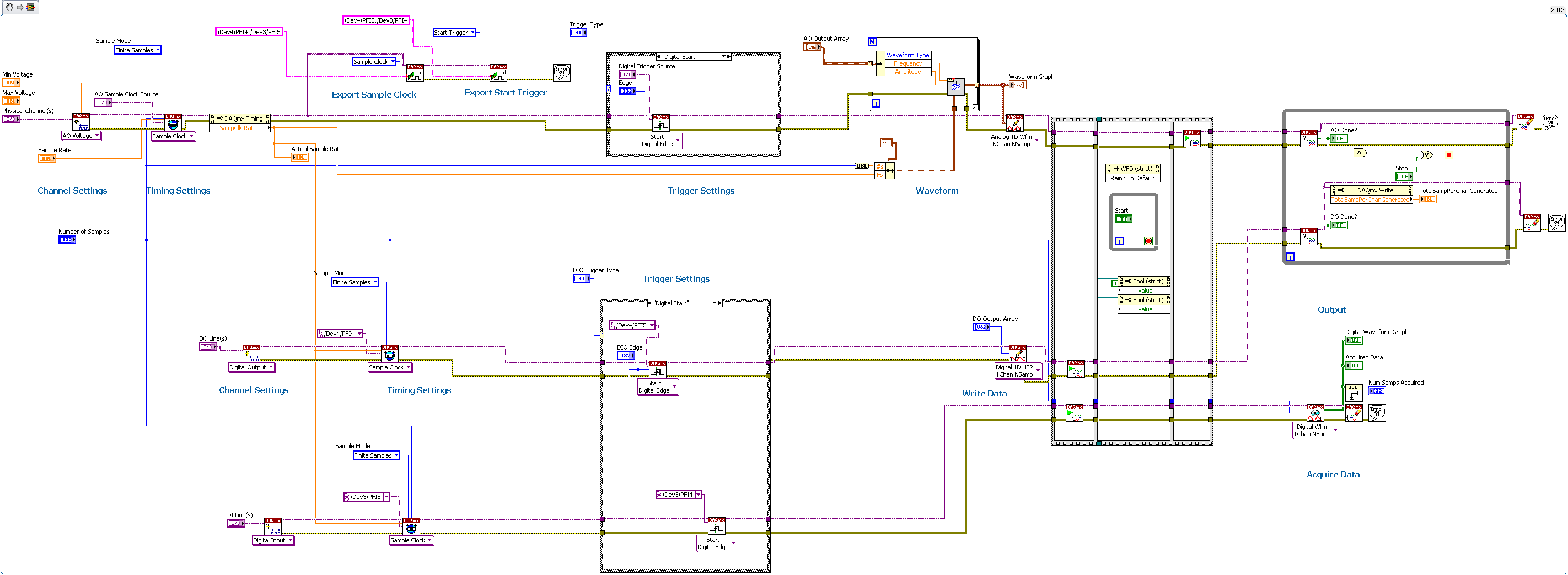
Several synchronization AO-DO-DI via DAQmx, external trigger devices
Having trouble getting the digital input to trigger analog output unit.
I have 2 AO cards (although I'm testing only with 1 device AO)
2 cards DIO - using one for output, one for input
All 4 cards are connected via a RTSI cable, and the cable is correctly condfigured in MAX, all 4 devices added to the cable.
I consider the AO the 'master' unit map In this test, I plead for a finite number of samples, and I'm outside triggering map AO.
As you can see, iI uses Signal export, export the AO and AO Start Trigger sample clock to DIO cards.
I'm using Labview 2012 on PC Windows 7.
The digital output is waiting for the AO trigger and appears off the coast of the AO sample clock synchronizing.
The digital input expires if I only fire at the time, so he does not expect relaxation.
any ideas? I tried all kinds of combinations.
Never mind! I solved the problem with digital input without waiting for the external trigger.
I just had to set the time-out waiting-1, so that he would never expire, and so he will wait for the trigger.
-
From a ReadWaveform on an external trigger?
I have a DigitalMultiChannelReader that I need to start reading a waveform when a change of external line. For example, I want to read Port3 lines 3 and 4, when PFI5 is high for a number of samples.
readWaveformTask = new NationalInstruments.DAQmx.Task ();
readWaveformTask.DIChannels.CreateChannel ("PXI1Slot6, Port3/Line3, Port3/PXI1Slot6/4", "", ChannelLineGrouping.OneChannelForEachLine);
() readWaveformTask.Timing.ConfigureSampleClock
"",
samplesPerSecond,
SampleClockActiveEdge.Rising,
SampleQuantityMode.FiniteSamples,
samplesToCollect);
readWaveformTask.Stream.Timeout = 1000;
readWaveformTask.Triggers.StartTrigger.ConfigureDigitalEdgeTrigger ("PXI1Slot6/PFI5", DigitalEdgeStartTriggerEdge.Rising);DigitalMultiChannelReader reader = new DigitalMultiChannelReader (readWaveformTask.Stream);
TODO: How to make the player doesn't start not the task here?
drive. ReadWaveform (samplesToCollect);The above code will start the task and start playback of the waveform as soon as 'drive. ReadWaveform (samplesToCollect)' is called.
How can I trigger a waveform acquisition using an external trigger?
CurtisHx,
In fact, even if the roads of the device shows a direct link between your PFI line and the trigger in MAX line, it only means that there is a possible link between these lines. You will still need to manually connect these terminals, which can be done easily with the method DAQmx connect terminals. If you need a detailed method explanation, you can find it here.
Maybe you are looking for
-
Equium A200-1V0 - need help with the installation of the recovery system
I WANT TO DO A FACTORY RESTORE, BUT CAN NOT FIND MY DISK AND WHEN I PRESS ON 0 AT START UP IT ME GIVES THE OPPORTUNITY TO RESTORE BUT ONLY WITH THE DRIVE AND I CAN FIND THE PROGRAM ON THE LAPTOP TO CREATE ANOTHER DISC! ANY HELP ON HOW I CAN RESTORE T
-
iTunes for PC 12: order of the song in the Album?
I find a problem with recently installed iTunes 12 for PC. I have a lot of albums containing several symphonies or concertos. I would like to (movements) songs in each album to play in order. If an album contains 23 Concerto of Mozart followed by Hay
-
I want to change my phone of android to apple, I have a large collection of music and need to know if I can use windowws xp to load itunes on my system, and if it will install ok thanx Suburbansteve
-
If I need to upgrade to service pack 2, which is the one I need for my computer
-
Dual boot Win 7 64 bit and XP Pro 32-bit (win7 installed first)
How can I set up: dual boot Windows 7 Ultimate 64-bit and Windows XP Pro 32-bit (Windows 7 installed first)? I have Win7 on a 2 terabyte HARD drive, with another 1 terabytle internal HARD disk and two 1 terabyte external hard drives. I have an Intel