Sample clock dependence with small signals data acquisition
Hi all
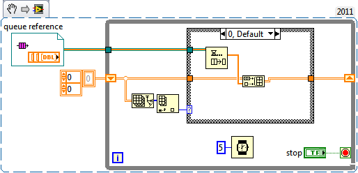
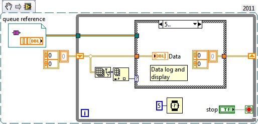
I use a NOR-9205 on a NOR-cDAQ-9184 and noticing some interesting dependencies of waveform on my sampling rate selected. It seems that small changes in the sample clock frequency have a significant impact on the measured waveform.
Quick background, I am in a position a signal with a ripple of mV ~ 10 with V 1.6 bias. I'm not interested in DC, only the AC signal but the NOR-9205 has only DC coupling. The application is a circuit where I expect simulations noise past the circuit must be greater than the higher noise frequencies. In the waveforms attached the background plot is the applied signal, and the top graph is the signal arising after that the signal was mostly annihilated. The two waveforms are measured with the NOR-9205.
I am aware that this measure is less than the precision of the NOR-9205, which has a maximum precision of ~ 3 mV in his +/-5V range. However, if I can't at least on the basis of shape which is good enough for me. I'm also now pretty curious that data acquisition is actually to create this
My best idea, is that it is a product of internal multiplexing of the 9205 with the DAC.
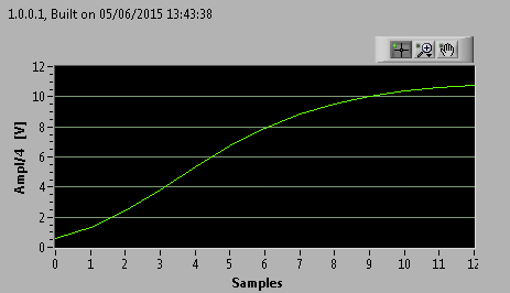
The first plot shows the waveform at 20 000 Hz, which is what I expected:
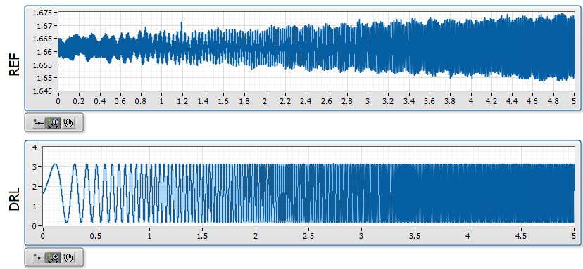
The second shows the waveform at 20 001 Hz, which seems to be modulated with a backup sawtooth:
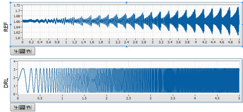
The waveform looks as expected for 20 000, 20003, 20004, 20005, 20008, 20009, 20010 and Hz 20011. The waveform looks like modulated to 20001, 20002, 20006 and Hz 20007.
Ideally, I would like to understand this problem so that I can configure the measure in a stable way that I can count on the basic shape of the wave. Has anyone seen something similar?
Tags: NI Hardware
Similar Questions
-
Hello guys,.
I have a general question regarding the units of packaging such as the USB-9263 analog output signal. If I can use it instead of data acquisition to provide an analog voltage output?
Thank you
ELA
Yes, the 9263 can provide 4 output channels analog voltage (+/-10 v range) with up to 1mA of current drive. Looks like: it refers to the short circuit of conditioning of signals and some protection against overvoltage. Link below is the User Guide:
http://www.NI.com/PDF/manuals/372406b.PDF
-AK2DM
-
Build a 2D with values of data acquisition
Need to collect data from various sources, 6 lines of total and average values over 30 seconds. So I used a table with 6 x 2D enter on each shift registers and table functions to complete the table. I used a timer elapsed to enable a case statement all about this package that clears the berries after 30 seconds then restarts next block of data gathering. It works very well, but...
The question I have is that the code looks too complicated and a waste. I tried with indexing for loop and while loop etc. but the data between the loop and the loop only "catches the first batch, ignoring the rest so the table is filled with the same value, I know this is obvious, really given rules loops etc.."
It feels like there is a much better way to do this, suggestions for a cleaner method?
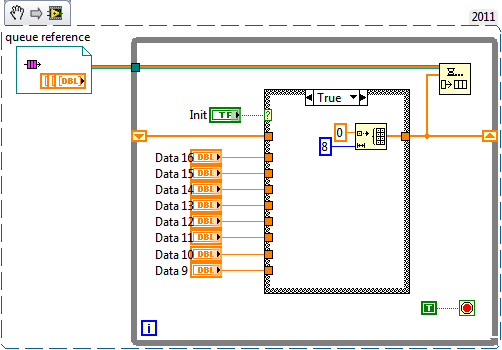
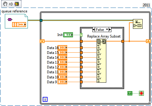
You initialize the array with a size of 10, you really don't need because you simply insert new items into the table its nothing but the picture of construction. Since you're inserting table and then the construction of brand new for a 2D painting all the time you duplicate values so he eats memory and you will find yourself in the mistake of leak memory. What you can do is initialize a 1 d array initialization with the number of channels and in all iterations just replace the values with a new one, so you will always have the last single value of all channels. Al same time write the table in a queue. In any other place where you want to save or view the data, you can read the data, and also you can connect it easily by reading from the queue.
Edit: Sorry I forgot your second 30 average requirement. That decides how much data, you can store in memory and it also depends on the speed at which you acquire the data. If you can give these details, it would be good.
(Correct me if I'm wrong)
-
sample clock 6551 exporting to PXI_STAR
Hello
The help files for the x 655 (devices-> NI 655 x-> hardware-> Signal Routing Architecture) is a chart that shows the 6551 as source's internal sample clock and the PXI_STAR as a destination. I tried to implement, but it is back with a runtime error stating that the material doesn't have this ability. I have the 6551 in slot 2 the PXI backplane. Am I misunderstood the routing table in the help file.
Part of the code...
Configure the internal clock generator to be Meg 2
ErrChk (niHSDIO_ConfigureSampleClock (* viGen [out_card_number], NIHSDIO_VAL_ON_BOARD_CLOCK_STR, 2.0e6));
export the sample clock on co - ax signal clock
ErrChk (niHSDIO_ExportSignal (* viGen [out_card_number], NIHSDIO_VAL_SAMPLE_CLOCK, VI_NULL, NIHSDIO_VAL_PXI_STAR_STR));
make a commit to start the clock output
ErrChk (niHSDIO_CommitDynamic(*viGen[out_card_number]));Thank you
Andrew
Hello Andrew,.
The documentation is in fact inaccurate. Only certain devices can actually lead the line PXI_STAR as destination and 655 x devices cannot. It was a mistake in our documentation and has been reported to R & D under ID #166056. I believe that the following devices can lead the line slot of two PXI_Star:
- PXI-4461
- PXI-4462
- PXI-4472
- PXI-4472 b
- PXI-4474
- PXI-5112
- PXI-7344
- PXI-665 x
- PXI-6682
Please let me know if you want to use one of these devices and we can have a person from their product group check that they will be able to lead the line PXI_Star.
Kind regards
Paul C. -
Data acquisition in LabView for other suppliers DAQ cards that NEITHER
Hello
I am a beginner in LabView programming. I have a 32 channels base PCI card DAQ (i.e. PCI-1602 of the manufacturer, ICPDAS) and I want it to interface with Labview 8.5.
So how cards DAQ in Labview 8.5, which are manufactured by other suppliers that NEITHER? Should I DAQmx (or some other driver) for that?
What are the other drivers/components required to access of data PCI-1602 (device) of LabView 8.5 acquisition card?
(1602-PCI card driver are installed in my win XP and dispalyed in Device Manager).
Please provide some tutorial above mentioned the problem to interface.
Please guide me in this regard. Thank you
Waqar123 wrote:
Hello
I am a beginner in LabView programming. I have a 32 channels base PCI card DAQ (i.e. PCI-1602 of the manufacturer, ICPDAS) and I want it to interface with Labview 8.5.
So how cards DAQ in Labview 8.5, which are manufactured by other suppliers that NEITHER? Should I DAQmx (or some other driver) for that? You will need the drivers from the manufacturer, of the Board of Directors. In your case, "ICPDAS.
What are the other drivers/components required to access of data PCI-1602 (device) of LabView 8.5 acquisition card? Same as above.
(1602-PCI card driver are installed in my win XP and dispalyed in Device Manager). Ok. Then take you care of my 2 answers above.
Please provide some tutorial above mentioned the problem to interface. To learn more about LabVIEW, I suggest that you try to watch some of these tutorials.
Please guide me in this regard. Thank you
According to what you do with the DAQ cards, they can do the job however, from experience, there are some functions that I could achieve with the cards NOR that I couldn't with 3rd-party maufacturers. This does not mean that this is your case. However, it is worth noting that it took me a while to understand why the code has worked with a single data acquisition card (NOR) but not another (Non-OR).
The drivers that you have installed may or may not include examples and code in VI. They may be DLL. If this is the case, you can write LabVIEW "Wrappers" around these functions, as it will simplify your life. If the drivers are in the form of DLLs, and there are no examples of LabvIEW or available VI, you must read on node library function call.
R
-
Problem with DAQmx Schedule VI (sample clock)
Hello to you all,.
I'm new to this forum, please bare with me. I have some experience with LV, but I am relatively new to data acquisition projects. I use LV2009.
I want to make sure that I use the hardware timing (instead of software distribution) in my project so I followed some of the threads here as sugested to use DAQmx Schedule VI. The problem is that no matter how I set the system I get the same error-200300 invalid calendar
type.The project is simple. I encode with 1000 pulses per
Rev and it is mounted on a shaft of a turbine water goes thru. I'm watching the frequency
and so the rotation of the shaft which tells me that the amount of water flows through the turbine. In the end, there will be 2 channels
by every encoder and ~ 3 encoders (turbines) total and calibrated the main meter that will give me constant impulses and all encoders will be compared to this master frequency.I'll use PCI6602 DAQ, but
now, for the development, I use USB6221. Let's say that the
frequency is between 500 Hz and 10 kHz. What I am doing wrong? Or maybe better to ask - what would be the right approach for this project?Thank you
Marty
Hi Marty,
It seems that your question is already answered here, but Jason is correct that the 6221 neither the 6602 support a clock sampling for frequency measurements.
As Jason mentioned, your best bet is also likely set the mode of synchronization for "implied". This means that the frequency value is sampled at the end of each period of your input signal. In addition, a solution that is clocked by the software (On-Demand) might be acceptable.
X Series DAQ devices allow an external sample clock to use for frequency measures (described in the Manual of X series). Frequency of sample-clocked measures are useful in very specific
circumstances, but it does not seem that you need this feature based on what you've described so far.(621 x) bus-powered M series can also be configured to use an external sample as the X series clock but do you not have the same features described in the manual of the X series.
I hope this helps!
-John
-
How the PFI to go top-to-bottom with sample clock?
Hello world!
I am very new to LabView and I try to do something very simple in the NI PCI-6534 and still not get anywhere (or do not know if it is the limitation of the hardware)
My request is to acquire digital data of 2 channels (16-bit each) of our Board custom designed analog-to-digital.
So far, I am in a position to acquire a finite amount of sampling digital (say 100000) and using a trigger to start (PFI6) to start the acquisition of our custom card board. Just to let you know that I'm feeding the PCI-6534 an external clock of 20 MHz by PFI2.
However, I want to send a signal to trigger recognition (high/low-rising edge) to our personal advice, saying: he did the acquisition of 100000-sample.
My problem is that whenever I try to use the lines of PFI signal with an internal sample clock, I get an error saying that I can't use the PFI lines with any sample clock. But my goal is to use a rising edge (low-high) to trigger back.
So far, I can pull the PFI4 high and used a timer to make it low. But the resolution of the timer is milliseconds (software) range. I would like to have at least a few microseconds.
I also tried using implicit since manual said that it does not require any clock but still get no result. Also, I couldn't find an example of implied clock and don't know if PCI-6534 supports.
Note that I'm able to use the clock synchronization of sampling with other DIO (Port 0 to Port 3) lines and get the result I want. However, I would need to use all our custom Board 32 - DIO for analog-to-digital data lines. So, using the line of PFI laccuse is the only choice.
If you have ideas/pointers, please throw it at me, I'll try them. Thanks a lot for your help!
See you soon,.
Yaseen KhanHi ykhan,
After validation, I noticed that it will not really work for what you are trying to do. The PFI lines on your 6534 are I/O static only as shown in the DAQmx help.
You will be able to control these lines, but only with software timing. You should be able to call and argue by their physical channel name. I hope this helps!
Kind regards
-
Sampling frequency and Nyquist theorem - data acquisition
Hi all
I have a rectangular steel beam that is affected with a weight of 100 kg and I would look for the modules able to sample the signal correctly.
The Nyquist theorem says that if half of the sampling frequency is higher than the input signal, it will be recorded correctly.
What I think about it before you buy a data acquisition module to find the signal of the rectangular steel beam? I will perform an analysis model by finite elements using the elastic properties or properties of plastic? Is the natural frequency of the associated structure of the input signal?
Thank you
Husband
Some technical assistance is appropriate, determine that the higher frequency component is interesting to your signal. Set your frequency of sampling to twice this value. In addition, to protect data, to build a filter of antisliasing of material it alleviates any energy above the highest frequency of interest.
Mike...
-
DAQmx data acquisition with persistent error of nyquist
Hi, I created a multi channel data acquisition vi (accelerometer 2 and 1 sound pressure) using models for producer. The vi is attached. Thanks to labview 2011. I get the error of nyquist (2 enclosed) when you make a bandpass filter between 50 to 5000Hz. This happens despite having put my sampling rate to 22050Hz. When I checked the output of wave I noticed that the signal has a dt 1 s. The text output to check the result. I could not understand how this is so since I had set the sample rate to 22 k Hz. Any help will be much appreciated. Thank you.
I would do something like that. You must calculate the dt of the set (with the recipricol) sampling frequency and use to initialize the shift registers. This way you only need to change 1 constant if you need to change your sample rate.

-
Multichannel data acquisition and 2D signals
Hello
[Use of labview 2011 license academic with NI9234 and cDAQ-9178].
I'm trying to read, display and record the signals from two isotronic accelerometers and a microphone at the same time for future signal analysis (FFT, etc.). I wish to display data of vibration and noise signals in real-time at 44100 Hz sampling frequency and display a waveform of final sampling, which takes about 40 years. I would like to then write the data to a file.
The associated block diagram, attached vi. I could view real-time each accelerometer and sound using iterations of the loop and split the signal. Unfortunately I record three channels of data in a table unique 1 d-wave form. It seems that the data is saved as iteration1 (ch0) .iteration1 (ch1) .iteration1 (ch2) .iteration2 (ch0) .iteration2 (ch1)... and so on.
Although I could show all three signals separately in the waveform graph, but I prefer these data to save as table 2D-waveform (each channel in a separate column).
I believe that this issue has been raised here (http://ni.lithium.com/t5/LabVIEW/Concatenate-2D-data/td-p/873409) unfortunately no solution has been proposed. How can I record the signals of data acquisition in 2D waveform?
Thank you.
I think to represent vi attached a solution architecture producer consumer for the problem mentioned above. Just thought I'd share to those who can live a similar situation that I had been faced.
-
Why data acquisition in an executable collect fewer samples?
Hello
I have LV2012 on Windows and SMU-6341 map in PXI chassis.
I have a task for the acquisition of data on I-1 on my monstrous application. Well, to get to the point, I have here a case where the task of data acquisition starts, waiting 20ms, reads all available samples and puts an end to the task. For the parameters see the piece attached. Then, the collected data is plotted on a waveform graph. Usually about 200 samples are taken in the case of data acquisition. Then loops shown sequence, until certain conditions are met.
Unfortunately a problem occurs when I deploy a rack application (exe) on a production PC some 600 miles away from me.
This is an example of what I get on my development PC (LV and runtime give similar results):
This is an example of what I get on the production of exe PC (13 iterations, bad luck
 ):
):It totally looks like the data acquisition task mentioned seizes one sample to an iteration of the loop.
I enclose a noodle dragged out of the main program. I'm about to test the version of this noodle on the production of PC in a few hours, but I would like to hear all the ideas that emerge.
Thanks in advance!
cubz wrote: from my experience, the continuous 'Samples' mode does not stop when the buffer is full. The loop of 4 seconds (with 10 k samples/s in the sample buffer 40 k)-that is to say samples how finished works IMO.
If the buffer is filled in continuous mode of the samples, you will get an error. I'm sure it's something you don't want. In this example, you have provided, you really should have finished samples and has said the acquisition of data to read samples of N. It is the only way to ensure you get all the data you want.
In regards to your differences between development and executable, the executable file tends to only not nearly as happening (Debug stuff for the most part), so it tends to run faster. If you're depending on a software clock, anything can happen (having a ton of little or no data). That is why we say you use the clock machine and get the number of samples that you actually want.
-
Real-time display at the high frequency of data acquisition with continuous recording
Hi all
I encountered a problem and you need help.
I collect tensions and corresponding currents via a card PCI-6221. While acquiriing data, I would like to see the values on a XY graph, so that I can also check current vs only voltage/current / time. In addition, data should be recorded on the acquisition.
First, I create hannels to analog input with the Virutal DAQmx channel create, then I set the sampling frequency and the mode and begin the tasks. The DAQmx.Read is placed in a while loop. Because of the high noise to signal, I want to average for example every 200 points of the current and acquired for this draw versus the average acquisition time or average voltage. The recording of the data should also appear in the while loop.
The first thing, I thought, was to run in continuous Mode data acquisition and utilization for example 10 k s/s sampling frequency. The DAQmx.Read is set to 1 D Wfm N Chan N Samp (there are 4 channels in total) and the number of samples per channel for example is 1000 to avoid the errors/subscribe for more of the buffer. Each of these packages of 1000 samples should be separatet (I use Index Array at the moment). After gaining separate waveforms out of table 1 d of waveforms, I extracted the value of Y to get items of waveform. The error that results must then be treated to get average values.
But how to get these averages without delaying my code?
My idea/concern is this: I've read 1000 samples after about 0.1 s. These then are divded into single waveforms, time information are subtracted, a sort of loop to sprawl is used (I don't know how this exactly), the data are transferred to a XY Chart and saved to a .dat file. After all that's happened (I hope I understood correctly the flow of data within a while loop), the code in the while loop again then 1000 samples read and are processed.
But if the treatment was too long the DAQmx.Read runs too late and cycle to cycle, reading buffer behind the generation of data on the card PCI-6221.
This concern is reasonable? And how can I get around this? Does anyone know a way to average and save the data?
I mean, the first thing that I would consider increasing the number of samples per channel, but this also increases the duration of the data processing.
The other question is on the calendar. If I understand correctly, the timestamp is generated once when the task starts (with the DAQmxStartTask) and the time difference betweeen the datapoints is then computed by 1 divded by the sampling frequency. However, if the treatment takes considerable time, how can I make sure, that this error does not accumulate?
I'm sorry for the long plain text!
You can find my attached example-vi(only to show roughly what I was thinking, I know there are two averaging-functions and the rate are not correctly set now).
Best wishes and thank you in advance,
MR. KSE
PS: I should add: imagine the acquisition of data running on a really old and slow PC, for example a Pentium III.
PPS: I do not know why, but I can't reach my vi...
-
Synchronization of analog and digital output with the external sample clock
Hello
First of all sorry for my English, I will try to explain what I want to do.
I want my PCIe-6321 to send two custom signals (modification sawtooths) on a mirror controller. I would also like to generate output with my card at the beginning of each tooth of saw. Everything must be synchronized with an external k-clock signal of 100 kHz. The idea is that whenever the PCI receives a trigger to external clock, it sends two analog output voltages and when he received 1024 clock ticks it will also send a pic of triggering TTL. What I do is first prepare the map and after that in a loop sending and modifing the output values of the two signals and at the same time send a digital signal Boolean in each arch, so when's done it 1024 iterations of the loop I send an event to the digital port. Attached you can see.
The problem is that I don't know how to synchronize both. Can I use the sample clock just to the analog output? I can use sample for the two outputs clock, or do I need to use the output of the meter? If don't know how to use it here.
If I do nothing else bad/wrong, I would be grateful for feedback.
Thanks in advance,
PabloI don't know how but I find the solution. I'm generating more than a positive value (as I was triggered maybe very fast the oscilloscope has been absent there). If I put the sample clock of digital output to use the sampling/ao/Dev1 clock that it doesn't, but if I put to use the same source as the OD (terminal where my external clock is connected), but the trigger to start the DO to be Dev1/ao/StartTrigger this works. I don't really know why, but it does.
Thank you for your patience and your help. I put here the final code.
-
Synchronization of data from different sample of data acquisition rate
I use a high RT 8135. I'm sampling of signals from analog pressure thermocouples to 20 ms and 10 ms. I use the stream network to transfer the data from the SMU on my host. I would like to be able to synchronize the timestamps of all data to the 1ms sampling note and record in a file.
Search in the file my sampling data 10ms end timestamp does not match the timestamp of 20ms, missing data... I know you have empty queues to get the rest data but is possible to interpolate any data to adapt a unique timestamp?
Thank you!
Hi aokada09,
Looks like you are facing problems resulting from parallel execution two loops you have. There is nothing necessarily bind the two loops together, so that each of them an iteration at the rates you specified, but are allowed to start each software (sort of random) dictates that they start.
To get a solid synchronization, share a sample between the two measures clock, but run the sample clock at 100 Hz for 50 Hz for thermocouple measurement and pressure measurement. You should be able to use shared inside the SMU chassis backplane clock. This will be as close as possible to synchronize without using a card of timing. The only real source of delay/tilt between readings at this point is the physical distance that must travel the clock signal. This will not lead to steep, but there will certainly be some (probably on the scale of the high-nanoseconds or microseconds bass). This article gives more information about the synchronization and the sample clock:
-
Measurement of low-cost input analog (4-20mA) with data acquisition
Hello
I would like to have a very low cost measurement system loop which I can plug in my laptop current:
I have a load, which is connected to a circuit of air conditioning/signal booster, which output a 4-20mA. I want to measure this current loop signal.
An idea for the lowest cost system? I think that the most NOR DAQ are too expensive and too exaggerated.
I have LabVIEW.
Use of remote sensing current low-value resistance, then measure the fall of voltage through it with the help of an acquisition of data 6008/6009? They have about $150.
You will probably need to amplify current-sense with a MAX4372 or similar resistance to achieve a result that allows you to use a reasonable scale on data acquisition. I measure the current through our products in almost all of our equipment to test in this way. The size of the resistance of meaning as a result. The 6008 is accurate enough, but it is not the fastest nor well presented. But starting at $ 150, they are hard to beat.

Maybe you are looking for
-
Firefox 22.0 can run on Mac 10.5.8 (Leopard) since it has code i386?
Firefox 22.0 has 1386 code (such as x86_64), and the only difference in Info.plist is basically being instead of 10.5 10.6 as in Firefox 16.0.2 LSMinimumSystemVersion. So why can't Firefox 22.0 running Leopard (10.5.8) with simple changes to the Vers
-
At 2.30 this morning some web pages expanded so that some parts of them became inaccessible. At the same time, the scroll wheel began to zoom just the visible part of the page inside and outside instead of scrolling up and down. The second problem ha
-
Links in various applications more open Firefox 3.6.3. What has changed?
Before the update of Firefox, clicking on a link in my applications (for example: MS Office 2000, Secure Shell) would trigger the opening of Firefox and view the Web site. After the upgrade process, Firefox does not open. Must open Firefox and paste
-
HP Installer has stopped working
I try to install the printer software HP on a Windows 7 Professional 64 bit computer. When I run the file it complete extraction and then I get the error message ar 'of HP Installer has stopped working ". I have two options - 1, close the program,
-
Power chose PS or PSE as a publisher of LR
I currently teach LR and can make deeper changes with PSE14 by pressing CTRL-E, which I am competent enough to. My subscription to Adobe CC gives me right to the PS, which I want to explore, but if I download, LR will detect it is there and LR will