Save the wave shape of power spectrum
Hey labview masters, I need help! I'm developing a labview program to calculate the power of a waveform spectrum injected into a signal acquisition interface 4461. The program gets the fft of the captured signal and return the array of power, as well as background noise spectrum. He is then sent to the host via a TCP connection.
Everything works fine except that I can't record the signal power spectrum more he sent to the host. I tried to trace all the x / y values via the command waveform.vi in the field, except that I can't add the axis labels.
Can you tell me how to trace the full spectrum of power, add labels and save it in the pc?
Thank you guys
João Matos
Export image is an Invoke node, not a property node.
Right-click on the graphic terminal of waveform and select Create > invoke node > export Image.
Lynn
Tags: NI Software
Similar Questions
-
Cannot save the T61p XP/SP3 - Power Manager problems, programs, limited systems available
Hi all - when I got this - Rockin '-mobile initially I could put my own power plans without problem. Now it won't save my new powerschemes. I try to create one, to complete the last step, and then the power mode is not in the drop-down list. I read somewhere on the Web that this may be due to SP3.
Also, the only one I have access to power management are reading video and performance. I tried to uninstall the power manager and the DLL associated with and then put it back, but that did not help. Also, I don't see any reference to this problem to be solved. Thanks in advance. This gets really annoying as I like to use as little energy as possible since I quite often use the computer on battery power.
Thank you! g-
Bravo - who did it! Thank you!
Here is the solution to save the future of research some time:
*******
Method 1: Use the Powercfg.exe utility to restore the default power mode
loadTOCNode (2, 'resolution'); You can use the Powercfg.exe utility to copy the power mode of the user by defaultto the currently logged user profile. You can do this because eating patterns are only related to individual user accounts. To copy the default user schema using the Powercfg.exe utility, follow these steps:
1. click on Start, click run, type cmdand then click OK. 2. at the command prompt, type the following command and press ENTER: powercfg /RestoreDefaultPolicies
********
-
Problem with redirect after save the wav file
I have a photo booth / audio that we created with flash that take a photo and record then it records audio testimony and records it. My problem is that, once the wav file is saved, I want to redirect them to a thank you page but can't seem to find a way to do it. Here is the code that I use to manage the registration of the wav file.
private void recordComplete(e:Event):void
{
var request: URLRequest = new URLRequest ("save - file.php '");
var loader: URLLoader = new URLLoader();
request.contentType = ' application/octet-stream ";
Request.Method = URLRequestMethod.POST;
Request.Data = recorder.output;
Loader.Load (request);
navigateToURL (new URLRequest (redirectPath), "_self")
}
I tried to add the navigateToURL at the end and it sends to this page correctly, but the wav file is not saved. I was wondering if there was a way to determine that the file is saved and then redirect to a thank you page?
Thanks in advance!
-justin
replace
public var redirectPath:String = "http://localhost/thankyou.html";
with
not sure that this should be public but it won't matter for testing.
public var redirectPath:String = "http://www.adobe.com";
-
Sneak peek of the wave shape curve
Hello
I need one more glimpse of the actual waveform curve comes to know the exact position where I am, when I zoom in and out of the chart with a cursor position for measurement purposes. Could someone help me please how to do this. Thanks in advance
Concerning
Julien
Julien wrote:
Could you please save on Labview 10 and post again
Of course, you can go.
-
How to change the chart of FFT Power spectrum
Hi all
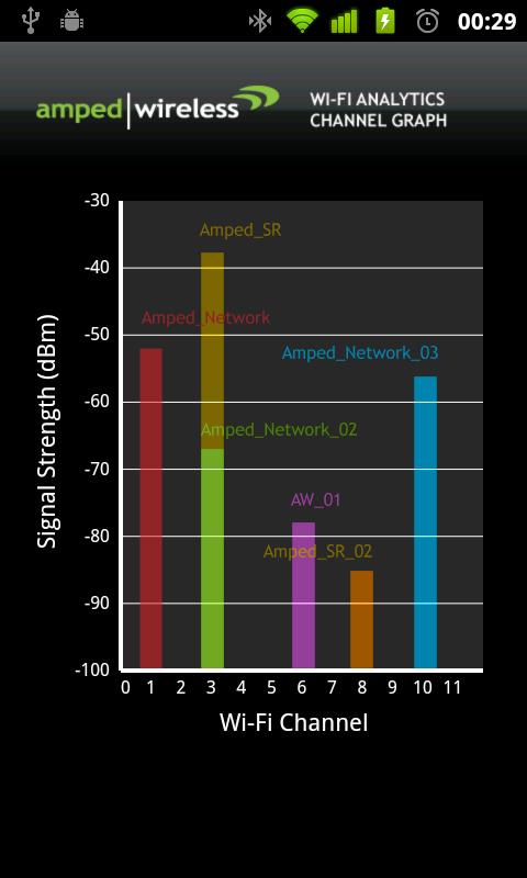
Could someone help me in Labview? I got a result as shown in Figure 1. However, I want the graph to resemble Figure 2 that we can define the range of frequencies for each channel in the y-axis and maintain the amplitude for the x axis.
How to change the chart?
Figure 1
Figure 2
I have the range of frequencies for each channel, which are:
Channel
Frequencies
Channel 1
2401-2423
Channel 2
2404-2428
Channel 3
2411-2433
Channel 4
2416-2438
Channel 5
2421-2443
Channel 6
2426-2448
Channel 7
2431-2453
Channel 8
2436-2458
Channel 9
2441-2463
Channel 10
2446-2468
Channel 11
2451-2473
Could only change the graphic on the front panel or have to change inside the block diagram?
Your answer is really appreciated.
Thanks & best regards.
-
How to increase frequency resolution in the power spectrum?
All,
I work on the analysis of data GET vi, and manage mucho when it comes to display a simple power spectrum which gives a precise simulation of sine wave frequency I use now. Most of the brain waves are between 1 to 50 Hz, and so I try to get a resolution of at least 1 Hz frequency. However, no matter what I do (increase the sampling frequency, use different sub vi and blocks), the chart plot only in frequency of 10 Hz increments. I know this must be a simple problem, but I can not find good documentation on this and would appreciate any advice anyone could give on this problem. I'm racking my brain here!
Nick
You need to acquire a second data to get the 1 Hz resolution. The increase in sampling rate only increases the bandwidth that covers the FFT.
Frequency resolution = 1/sampling
Scale of frequency rate of sampling/2 =
For your application, you will need to have a sample of at least 100 Hz rate. At this rate, you must purchase 100 samples to get the 1 Hz resolution. At the 1 kHz sampling rate, you will need to acquire 1000 points for the 1 Hz resolution.
-
'power' and 'size' in the power spectrum?
When I choose "power at the stage of the power spectrum, numbers in my data were negative. I don't understand why. What is the difference between "power" and "ten factor"?
And what are the "dB" and "linear" in the average of actual size selection? "DB" means the following equation? Vnorm = 20 * log10 (Vnorm)? 'Linear' means greatness?
Thank you very much!
-
Hello
I have a question about BER and SNR and I would appreciate your help.
I have a power Spectrum (live with the presence of interference) and I would like to know in what parts of the spectrum, I can achieve a target BER (lets say 10th-3)
My suggestion was to first determine the signal investment ratio on the graph (for BPSK) and then search for available positions in the spectrum that can give me this SNR
So say for 10-3 BER, en No. DB 9 (on the graph)
If Eb (dB) = 9 (dB) + No. (dB) or Eb (dBm) = 39 (dBm) + No. (dBm)
now my questions are?
1 - instead of BER can I focus on NRS and are my calculations correct?
2-noise background in my power spectrum is observed from BDP-110-130 dBm is not a value constant .what should I do in this situation to find Eb?
3. What about interference? because WLAN is perhaps the received power - 50dBm in this situation that the SNR appropriate therefore to achieve this BER?
is it correct to say Eb should be = - 50 + 39 (dBm)
I thik find positions them avaiable in the spectrum (especially 2.4 GHz) to achieve a certain BER or SNR should not be as easy as I think.
Hi tintin99, the calculation seems to me.
For the second question, I don't know what application you are considering, so it is difficult to answer. If you measure performance to highlight, I'd go for the peak noise. To help us to give an exact answer, you provide more information about your application. For example, NEITHER-6115. The following link will be useful: NOR-6115 noise floor.
In case you're only interested in theoretically calculate the background noise, please check for the radio receiver noise floor. According to the definition, you can calculate the background noise as follows:
Background noise =-174 + NF + 10 log bandwidth
Where NF is the noise figure.
I hope my answers help. Still once, for questions related to the concepts of communications, please try discussion forum, I mentioned above. RF meter of NOR, please post to measure RF devices
-
Coercian dot on the power spectrum
Hi all
Was just curious to know why I have a point constraint on my FFT power spectrum when it fed a waveform? I thought (and detailed help is agree with me) that a waveform has been the type of entry required. There may be more going on here that I realize, but clearly I'm not.
As a sidenote, I'll you this because I replace an express VI in an application, that they gave me to end up and the express power VI spectrum seems to give results that are disabled by the square of the input function. OK then that sentence makes little sense, what I mean is when I plug a function up to my DAQ board generator and supply a sine to a known frequency spectrum of power express VI sets out 16 Hz instead of 4 Hz, 2500 instead of 50. The spectrum of normal power VI works fine. Do not Express VI anyway but just curious.
Thanks in advance!
Is the matrix Y DBL? SGL or EXT would produce a dowry of coercion.
Lynn
-
Collect data from specific frequency of the power spectrum
Hello
I want to know how to collect data from specific frequency of power spectrum file. I'm trying to separate data from specific frequency of the original file.
This will depend on much how your data is stored. You will need a way to read the file in LabVIEW and then a way to identify the data you want. I often record data in a .csv file, then I use "Reading worksheet" to get the data in a table. Then, you can simply use 'Index Array' to get the datapoints you need.
-
How to save the Agilent E4446A spectrum analyser plots
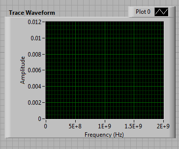
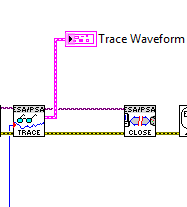
Hi all, I am a newbie to LabView. Now, I'm trying to store data (plots) of the Analyzer of spectrum of Agilent E4446A (SA). I was modifying the sample program (called Agilent PSA series ESA acquire Trace) of the driver of VISA. But I got stuck at the end of the program (I have attached the photos). When the SA have the plot of exact spectrum shown in the window "Waveform of the Trace" in the front panel, I don't know how to set up the program so that it stores the plot of the screen in format worksheet automatically. What I'm doing at the moment is manually, right-click in the waveform trace window and select "export". It's too slow to follow a few quick evolution results of SA. I was also trying to change the output of the function "Mark read" in his library of drivers. The production cluster (pink line) consists of the flow of three initial data (double) X, X increment (double) and Trace (table 1). I can not connect this cluster of data to 'Write in a file as' vi more, it's about the only life-saving method, that I worked with... I really want to learn how to automatically save the data in the format spreadsheet out of the plot.
Thanks a lot for your help!
-
Unit of the y-axis of the power spectrum
Hello
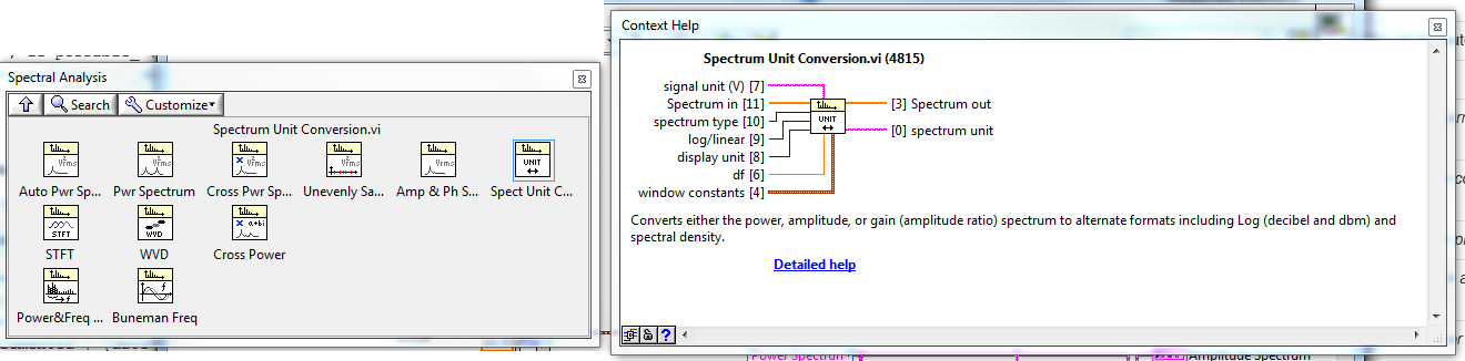
I am acquisition of acceleration of an IEPE accelerometer. Units of the axis y of the signal in the time domain are in (g). The signal in the time domain is then injected into the Spectral VI Express measures to obtain the power spectrum of the signal. In the Spectral Measurements Express VI, I put the results of linear and the window (Hanning). My very basic question is: what will be the units of the axis y with the linear option power spectrum and how can convert their return to unit (g). If you provide an example of calculation that would be very appreicated. One of my simple code is attached.
Concerning
Unit Conversion VI spectrum lie in LabVIEW palettes: functions > Signal Processing > spectrum analysis
-
How to show the output of the signalexpress power spectrum in data dashboard
Hey guys.
I made a program that collect analog data from two sensors in vibration, and then I use the signalexpress power spectrum to get in the frequency domain.
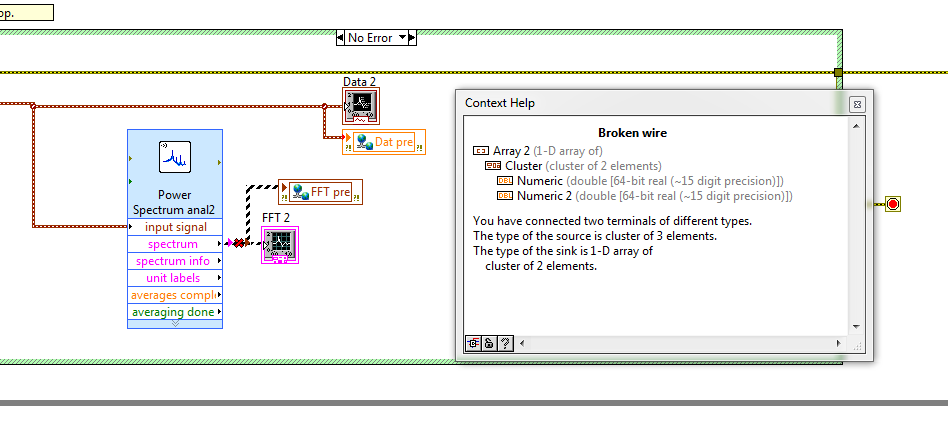
I would like to show the signals and the FFT in dashboard of data.
It is not possible to display the data directly because the XY graph in data dashboard supports only the two figures on the right cluster table?
Is it possible to convert data from the spectrum of power signalexpress table of cluster of two numeric values?
Or any other ideas would be appreciated
-
bandwidth of the function "power spectrum".
I use signalexpress 2009. To analyze the acquired time signal from the area of the previous step in the same project, I applied the power spectrum function.
DAQmx Aquire step is configured as follows:
Acquisition mode: continuous samples
samples read: 1024
Rate (Hz): 1024
With this configuration, I expect a bandwidth of 0-512 Hz power spectrum analysis. Instead, the function of the power spectrum gave me 0-820 Hz frequency components.
How can I trust the result of 512Hz on?
I've attached screenshots of:
(1) my application project configuration
(2) result of frequency domain
Very useful information, thanks to you both for helping!

-
How to capture a .gif of a spectrum analyzer file and save the file in PC
I want to capture a .gif from a spectrum analyzer file and save the file to the PC, but I have a problem when reading data from the instrument. I don't know how to format the string has obtained from the instrument, when I use '%s' or '%t' as string format to read the data from the instrument is truncated.
my code are, could someone tell me where I'm wrong?
char resultsArray [5000];
viPrintf (hSpectrumInstr, ": MMEM
 TORCR ' C
 IMAGE.") GIF "\n"); "
viQueryf (hSpectrumInstr, ": MMEM ATA? '") CIMAGE. (' GIF'\n ', '%t', resultsArray);
printf ("%s", resultsArray);
GetChar ();as you can see your code is not readable, can you post a screenshot or, as before, a Word document?
When you use "%b" table must be of type ViInt8
Maybe you are looking for
-
NB100 Linux - problems with Linux update and BIOS
Toshiba NB100Memory 1 GB - Kinston - KTT667D2 / 1 GUbuntu 8.04 - Ubuntu Netbook Remix - CD from ToshibaCD-rw/DVD-rw LG GE20 externel USB keyKeyboard differences Hello I was very happy to buy my Toshiba netbook. First of all, I configured the system r
-
A rather complicated task of string
Hello guys! Today I had a bit of a mess when doing a program for my company. I'm reading from a .csv file that is containing information on electrical components. I read the cell in a table for later use. No problem at all. Now the hardest part: Let'
-
filtering of the data sent to write to the file of measure
Hi everyone, I was wondering how to implement a "filter" that prevents the data to write in the function "write into file measuments. Say if the incoming data is a 0 (DBL), hwo to prevent it from being written?
-
If an update is cancelled and then installed?
Why these two incidents are recorded in Windows Update for Vista? How one removes the obiter canceled these two incidents are noted on the update can I thnaks for quick reply
-
I have a Dell Inspiron 1525 and I need drivers for Base system device after installing Win 7.
My laptop used to have Vista on it. I had a big problem with it, so I used fdisk to remove all partitions. I made an installation FULL of Windows 7 and all is great, but when I go into Device Manager, I show an error with the Base system device. I