SCB-68 AIGND vs AIGND
Hello
I apologize for the enigmatic title, but I'm a little confused on the difference between the screws AIGND fastons (67, 32, 64, etc.) and the AIGND on the area on the conditioning of signals of PCB SCB-68 box.
I'm trying to accurately measure a signal 0 - 10V on analog channel 1 mode differential. I followed directions (see link) connection for differential measurements by adding resistors of polarization on the sign (+) and (-) entered to AIGND pin # 67. With this configuration I sometimes see saturation in my measurements because of the high common-mode voltage. I then withdrew my PIN # 67 AIGND polarization resistors and added resistances of polarization in the region (RC14 and RC15) as suggested in figure 5-1 conditioning of signals of PCB and my measurements seems correct and do not saturate. It seems to me that these two should be the same, but I get different results. Measures of resistance between screw AIGND fastons (67, 32, and so on) to the AIGND showed high impedance which suggests that they are not the same conditioning of signals of PCB. All my switches are assigned to the default settings.
What is the difference between the two AIGNDs, and that AIGND should I use?
SCB-68 68-pin shielded connector block the user manual:
http://www.msm.cam.AC.UK/mechtest/docs/scb68%20Manual.PDF
Material:
PCI 6221 M data acquisition card
SCB-68 interface
Best regards
HV
HV:
These two AIGND are connected inside the data acquisition card, it will appear an impedance high unless the SCB - 68 on the DAQ card. I measured ~ 35Ohms when connected, open the circuit without. Additionally, make sure that switch S3 is down, by trial and error, I've found this causes impedance jumps.
Hope this helps,
Tags: NI Hardware
Similar Questions
-
Hello all,.
I have a beautifully SCB-68 connector block 68 pins. Can anyone provide me with the wiring diagram?
I went through the guides provided, but I have a few questions.
(1) how exactly work the switches?
(2) what is the need to provide + 5v to the part of conditioning of signals? (As for signal conditoning, we use some resistors and capacitors)
(3) where do we always connect us our signal? It is always the terminals screw or is it depends on the requirement of signal conditioning?
(4) if we use a conditioning of signals, which are input terminals? And what con terminals signals reaching data acquisition?
Concerning
-Vaidhin.
Hey,.
the Circuit diagram is shown to these PDF on page 82-83. (SCB-68 68-pin shielded connector manual user Block)
The sensor you want to use is never connect with the Terminal screw,
The switches have the following functions:
S1--> 5V supply
S2--> DGND
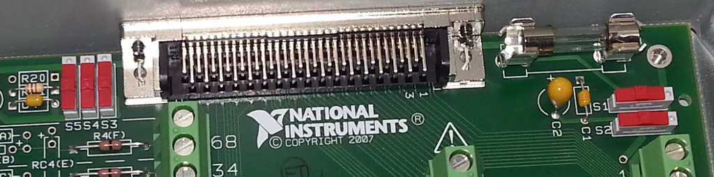
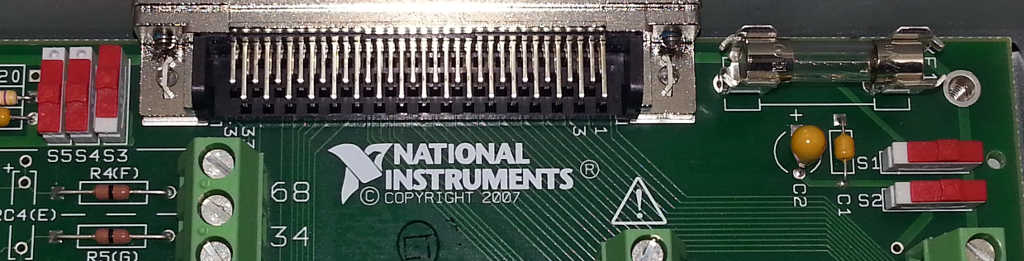
S3--> AIGND
S4--> PES or differential measurement
S5--> (cold junction Compensation) CJC
Best regards
Basti
-
SCB 68 rigged with potentiometer, have problems...
[I am preparing a graduate in the laboratory material that I work so much that I apologize in advance if I misuse of terminology, I'm not quite familiar with it]
I have a SCB-68 block connected to a computer through a PCI-6289. I can see the device in MAX and he claims an automatic test.
I'm trying to wire two 5V linear potentiometers in the block. Right now, I have the one with the power and return the wires in the terminals of screws 68 and 67, which tells me that the pinout diagram are AI0 and AIGND. The potentiometer should vary from ~ 0V full extension to 5V to complete removal. Instead, run a test on results AI0 massive fluctuations not correlated randomly.
Another question here suggested he switch to A1, I did, but no other results so I moved them back.
Someone has any advice on how wire properly this configuration? Thank you.
Problem solved. It turns out that the problem was because I was in differential mode, I needed to have the two wires on the pot in two separate channels. Hang them up to AI1 and AI9, everything works as it should. Logic wants future pots can be added in channels 2-10, 3-11 and so on.
Thanks for the help.
-
I have an interface SCB-68 box and that you have configured for the mode of direct crossing. I want to just make sure that I set the switches correctly.
Here's how the switches were when I first opened the lid:
and here's what it looks like after that I changed the position of the switches:
A set the switches correctly for direct crossing mode?
Thank you
[Tim]
The S1 & S2 in the manual see the same same switches if the letters across the switch.
-
OR PCI-MIO-16-1 & NI PCI-6070E digital outputs to scb - 68 to the electric circuit
I am designing a circuit and trying to the NI PCI-MIO-16-1 & NI PCI-6070E DAQ from the interface and the SCB-68 to my small circuit. The outputs are 0 (low) to 5 (high) Vcc. I underdstand the NI PCI-MIO-16-1 & NI PCI-6070E are identical regarding the outputs Digital 5 volts? Also the current will be enough to light an LED on a PS2501-4 or an Octocoupler of 4N38? If this is not the case, what I need to do to amplify the current. Or if you have any suggestions on the resistances, capacitiors, etc. Please let me know. Thank you!!
You are right in your way of thinking! From a source of 5 volts, resistance of 500 ohms in series with your LED will provide enough drive in math class of ohm's law you have already provided.
Paul C
-
SCB-68 digital pins returns incorrect values
Hi all
I use a SCB - 68 is connected to a PCI-MIO-16-4. I just want to use the digital pin on the SCB-68 to high/low otuput signals. I test the memory in 'Measurement & Automation Explorer', under 'panels of Test '.
The analog output works as expected and return values of voltage is entered.
The digital pins, however, give me really strange values. When I configure port0 to "all out", the voltage measured at all digital pins is 4.54V, no matter if my selected state is 'very high' or 'low', except pin19/DIO4, that always gives me 0V.
Should it? What are some possible solutions?
Thank you
A
No, it's not normal, assuming that you measure on a device output and referenced to dgnd. It passes self-test? The Council is an old model. Who used it before you? It could easily have been damaged. Taking the scb-68 and the cable out of the picture, have you looked at the output of the DAQ card with nothing plugged? How about the end of the scb-68 cable connected?
-
Problems to use two scb-68 has the NI PXI-6225
Dear nor Forum,.
I have a chassis NI SMU-1078, with embended OR PXIe8135 controller. One of the slot is busy with a PXI-6225. I for a long time successfully using 1 connection SCB-68 block a with the PXI-6225. Now, I need another channel to analog output on top of OD uses two that I am current. I plugged another SCB-68 connector Panel at the PXI6225, but I could not see analog outputs on this second bedroom. I could not see more channels to DAQmx AO create channel VI
The PXI-6225 has only 2 analog outputs. The second connector only has analog inputs.
If you need more than output analog, you can take a look at the SMU-6738, which includes 32 analog outputs.
-
SCB-68 Terminal Block quick reference label does not match PXI-7831R pinout diagram
I want to connect 3 analog inputs for the of IO reconfigurable NI PXI-7831R Module, use the connection series SCB-68 M block. I noticed a gap between the analog inputs, shown on the terminal block of the SCB-68 quick reference Label and the analog inputs captured in the pinout diagram 0 connector NI PXI-7831R. For example, the NI PXI-7831R connector 0 pinout diagram shows AI3 - and AIGND3 on the 29 and 30 pins, respectively. The label for quick reference of SCB-68 watch GND AI and AI 3-pin 29 and 30, respectively. There are at least six other cases where there is an incompatibility between the quick reference label and the pinout diagram. Has anyone else seen elsewhere?
Look at the label of SCB - 68 quick reference? M-series would be for the cards M Series DAQ devices where as the PXI-7831R is in the R series. You can see the difference here in this KB which has both the M series connector and connector M 7831R.
I hope this clears up things!
Greetings from Austin,
-
How to connect signals Ni SCB - 264 X
We bought PXI switch 2532 with TB-2641. We also have
bought burst of SCB-264 X. I have a question about the signal
connections. SCB-264 X is supplied with only the connections of signals (C0, C1
etc). But what of the ground for each signal. How to connect the
mass of each signal signal.Thank you
Kitenge
Hi Kitenge,
The connection TB-2641 block creates a configuration of matrix 8 x 64 1-wire for the NI PXI-2532.
1 - wire configurations are typically used for single-ended signals: when he shared there or return a common ground. In these configurations, the constant signal line is usually wired externally (not changed).
If a part of your application requires switching differential signals (2-wire), you can use an additional column for tracking on the ground of each signal. Similarly, additional lines are required.
If all your application passes only signals from 2 threads, then the TB-2643 or TB-2644 may be more appropriate than the TB-2641.
The connection TB-2643 block creates a matrix 4 x 64 2 wires.
The connection TB-2644 block creates a 8 x 32 2-wire matrix.
I hope this helps!
Chad Erickson
Switch Product Support Engineer
NOR - USA -
Hello
I brought a PCIe-7842r, and it comes with the SCB, 68 a, as the connection block.
I want to use the connection block for analog and digital output entry, so I plugged the pin68 and PIN 67 with two sons. 68 pin and PIN 67 on SCB68A is to HAVE it + and I-on the PCIe 7842r too, so it fits perfectly.
Next step, I want to use the PCIe 7842r to a digital output, and I intend to use the 36 pin and pin 2, which corresponds to DIO0 and DGND.
However, pin 36 and on the SCB68A pin2 is DGND and PFI14, which does not match the result of the PCIe 7842r.
Y at - it suggestions for dealing with this problem?
Best,
Matthew
MatthewTang wrote:
On page 9, you will need to enlarge to see the label
If you look at the label on this page closely, you will see that it is for M and X Series DAQ devices. You must read the section on the use of the SCB-68 has as a Feedthough Direct (page 14) and use the code I linked at the earliest for the R series card.
-
SCB-68 and PCI-8331 which is to convert my analog sgnal in digital % 3F
Long ago, about 7 years ago I worked on a project in which I photodetector interface to my computer through the SCB-68. All of the SCB-68 has been connected to the computer using the card PCI-8331.
Now my entry is an analog signal of photodetector but the programming interface, I was getting numerical values for the calculation. Now my confusion about the task of conversion performed by what part of this connection?
SCB - 68 has convert the input signal and the provision of digital output? or PCI-8331 was scanning before delivering information to the computer? or labview was after getting the signal of PCI-8331?
can anyone clear me please?
Thank you!
Of course there was a DAQ card somewhere.
-
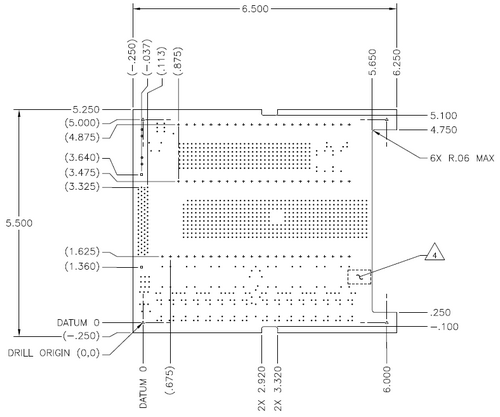
layout spacing on SCB - 68 pin
What is the axis of the model space on a map of derivation SCB-68? And what would a good part number for adding additional screw terminals to the area of the comp?
Thank you
PL32:
0.100 "spacing, here is an example of terminal blocks, there are many other different manufacturers. Just make sure that the holes in the area of the model are large enough to accommodate the pin of the terminal block.
http://www.alliedelec.com/catalog/PF.aspx?fn=300.PDF
-AK2DM
-
6509 PXI and SCB 100 Port 0 and 3 Port have lines that are high
Hello
I work with a PXI-6509 connected to an SCB-100. When I run the test panels lines 0,1,2 are high on port 0. 0,1,2,3 lines are high on port 3.
I have a voltage of 3 volts measured between Port0 line 0 and Gnd (PIN 47 and PIN 50). Nothing is connected to my SCB-100.
I put the switches for the recommended positions for Digital passthrough.
SW1, SW2, SW3 => on
SW4, SW5-online off
SW6-online on
Please notify
I found the problem!
It was a twisted spindle. Straightend out and now it works!
-
Someone next to the circuit board inside the SCB-68? Thank you.
Sorry, I misread your message. I think that's what you're looking for:
-
I suspect I already know the answer to this question:
I have an PXI-6224 M-series data acquisition card and a terminal of the SCB-68 block and want to take action using a bunch of 4-wire RTD. Is the power to the power source for these measures 6224, or is - not possible with the hardware I have?
I know that NEITHER you propose other solutions to my problem: I am interested to know if I can do these measures with the device that I currently have on site.
Thank you!
Hello Jeffrey,.
You have two options here, but it doesn't look like you need some hardware.
The SMU-4357 built conditioning of signals, but it will not work on the chassis curent you have:
http://sine.NI.com/NIPs/CDs/view/p/lang/en/NID/210596/
We also have an option with the NI 9217 cDAQ, but once, it gets you into a different platform:
http://sine.NI.com/NIPs/CDs/view/p/lang/en/NID/208804
We used to have an option that we sell no more - the SC-2042RTD. If you are lucky and have one of them on hand so here's some info:
http://digital.NI.com/public.nsf/allkb/4FF2C0F8D11B99B486256F4C006DCEA0
You can also use these two elements in conjunction with eachother with your current PXI card:
http://sine.NI.com/NIPs/CDs/view/p/lang/en/NID/12311
http://sine.NI.com/NIPs/CDs/view/p/lang/en/NID/10778
Finally, you could get an SCXI chassis and drop them in:
http://sine.NI.com/NIPs/CDs/view/p/lang/en/NID/201609
Thank you
Joel C
Technical sales engineer
National Instruments
Maybe you are looking for
-
SkypeSetup.exe remains at 0% forever and will not download
Hello! Once I had problems connecting to Skype so I uninstalled thinking this may help, but when I tried to download Skype setup once again he would not start the download and would stay at 0% forever. My internet connection works fine. I waited a fe
-
Satellite L650 - no sound on the TV using an HDMI cable
using a HDMI to connect to the TV picture cable works fine but no sound through the TV, sound out of speakers to computer. How can I configure so sound comes through the TV?
-
Possible outcome - QVariantMap - GroupDataModel
Not sure, but could be a possible problem: It seems that QVariantMap mess up if any key other than "countryName", "CityName" is used. I tried in my sample program also tried to change the code to: https://developer.BlackBerry.com/Cascades/documentati
-
BlackBerry Smartphones recover lost or deleted messages?
Hello world! I'm sure this has been asked several times already, but is it possible to retrieve emails lost or deleted in my blackberry account? I tried support RIM & they said that they have no way to achieve that emails do not remain on the server
-
Win7 64 bit SP1 opens Control Panel then message pops up saying explore stopped working and closes
I use the following system Windows 7 Edition home premium SP1 Sony Vaio model SVE14A15FAS I guess that S is for money, I noticed that SVE14A15FA only in the site 64 bit Performance of kaspersky internet security 2012 to protect the laptop I also run