separation of two edges using a digital output
I am using a DAQ, PXI-6229 map and programming in c# .net.
I'm claiming a falling edge on PFI12 used as a digital output, and I need to measure the time between this edge and a second front on PFI8 used as a digital input. I have implemented the code using some examples I found. I don't know when to to argue the signal on PFI12 in order to be read at the right time. Playback must be put in place before the signal is asserted, but I do not know how to set it up it up properly.
Here is the code I have so far:
Public Sub MeasureAcquisitionTime()
{
DigitalSingleInputTask = new Task();
CIChannel counterSetup;
firstEdge = CITwoEdgeSeparationFirstEdge.Falling;
secondEdge = CITwoEdgeSeparationSecondEdge.Rising;
Double minTime = 10-3;
Double maxTime = 60F-3;
String auxCounterInput = "/" + CardName + ' / PFI12 ';
String gateCounterInput = "/" + CardName + ' / PFI8 ';
counterSetup = DigitalSingleInputTask.CIChannels.CreateTwoEdgeSeparationChannel)
CardName + ' / ctr1 ', 'counter',
minTime,
maxTime,
firstEdge, secondEdge, CITwoEdgeSeparationUnits.Seconds);
counterSetup.TwoEdgeSeparationFirstTerminal = auxCounterInput;
counterSetup.TwoEdgeSeparationSecondTerminal = gateCounterInput;
DigitalSingleInputTask.Control (TaskAction.Verify);
runningDigitalTask = DigitalSingleInputTask;
counterInReader = new CounterReader (DigitalSingleInputTask.Stream);
Double data = counterInReader.ReadSingleSampleDouble ();
}
I'm glad to hear it.
paofthree wrote:
Is there a way to make a measure of separation of two edges on the analog inputs of the PXI-6229?
The only way would be to constantly acquire the analog input voltage and calculate the separation of the two edges in the software.
Best regards
Tags: NI Hardware
Similar Questions
-
Manchester in transmission/reception of signals using the digital output of the PCI-6224
How a manchester signal can be sent and received using the OID of the pci card 6224?
I want to create a signal NRZ manchester on a digital output channel and then have the possibility to receive and interpret the same type of signal on a digital input channel.
Any help would be greatly appreciated.
Hi VJohnson,
You might find this post of discussion forum useful.
Looks like LabVIEW has not Manchester coding/decoding built, but do able in your VI by replacing all the elements with the corresponding elements of two and using double the speed of transmission as your clock frequency.
Thank you
Scott M.
-
Is it save to use the digital output as a digital input for another channel signal
Hi all
I know it's a stupid question, but I don't have another generator of signals by hand. What I want to know is, can I use the signal digital output of my USB-6001 as an input for the same signal device, but on other digital port? I wasn't directly because I don't want to burn the device...
Thank you
Done all the time. No problems.
-
source timebase external meter in the task of separation of two edges
Hi all
I use a Board OR 6220 and want to make something very similar to what is described in the knowledge base article "how I count Digital edges between Start and Stop relaxing on a NI 6602 Council of counters/timers?
Anyone know how I change the example program "TwoEdgeSep.c" do not use the internal time base but to use an external source (that I want to count the edges?)
Thank you for for your time.
ULI
Hi Uli,
You must add a call to DAQmxSetCICtrTimebaseSrc before starts the task to configure the hardware to use an external time base. You also probably want to change the DAQmx_Val_Seconds
DAQmx_Val_Ticks parameter in
the DAQmxCreateCITwoEdgeSepChan
function assuming you want your result measured in terms of the external clock ticks.Best regards
-
Can I stop a separation of two edges with infinite time-out?
Hello!
I use the example VI: "soul two Edge Separation.vi ' (see the Archives of this message) with a USB-6251and NI a timeout that is infinite because I Don t know when I need start a new measurement. With the features I need to stop the DAQmx VI "DAQmx Read.vi" If this VI Don t stop in a PRE-DETERMINED time (10 seconds), but I do not know how I should do.
I can´t use a guard dog, because the NI USB-6251 haven´t housing a guard dog. I try to reset the daq with "DAQmx Reset Device.vi", but when I do, the daq break. I also try to use 'DAQmx control Task.vi', "DAQmx's task made" and "DAQmx Trigger.vi" with reference - no, but this screw never run until the end of the "DAQmx Read.vi.
Thank you.
Try the joint. It is registered as 8.0 because I do not know what version of LabVIEW you use.
The card I have in my machine cannot perform the task you want, so I don't have a chance to test it.
-
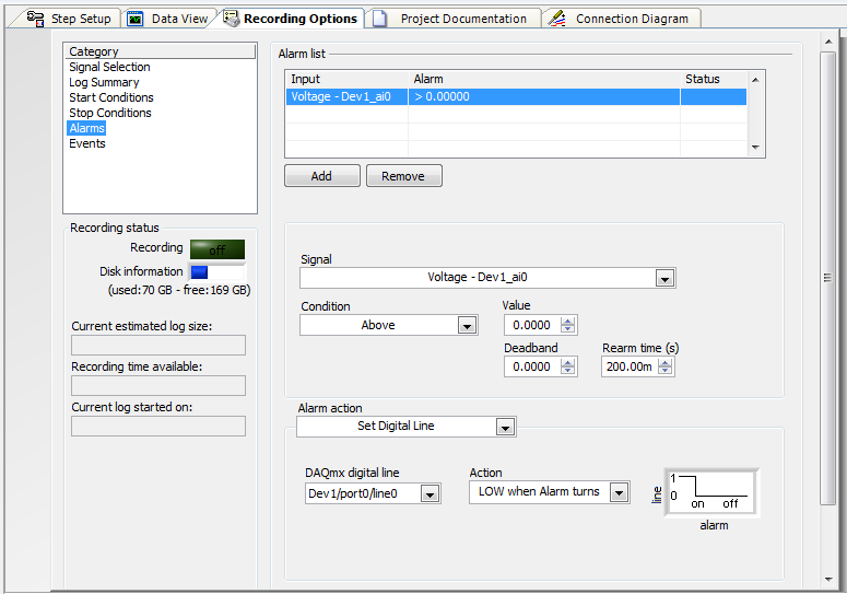
an alarm can be set to control an external device using the digital output?
My employer is considering buying a 6210 DAQ and SignalExpress (we currently use a branded DATAQ device).
Looks like I can use the alarm function SignalExpress to define a logic high or low line, controlling a SSR to stop a pump (a non-critical application).
Can I use SignalExpress in this way?
I know LabView can do, but there is no way that the company appears for him.
Thank you.
Hi Jack, this is Paul with Applications Engineering at National Instruments.
SignalExpress supports the functionality you want.
«Once you have configured your signal to acquire you can go to "Save Options" > "Alarms" and then set the alarm conditions, and then choose your Action to alarm as «Defining the digital line»»
I've attached a screenshot of the example of this configuration.
Note here that I put it down when the alarm turned on. You there are other options, including a rocker.
Let us know if you have any other questions!
Paul
-
When I pulse or measure of separation of two edges, using the implicit synchronization, DAQmx chooses (I think) an internal time base appropriate for the measurement. My X series on Board (a 6320) has for example a time base internal 100 MHz. I think I can apply to the use of a base of specific time (using the Set accessor of property DAQmxSetCICtrTimebaseSrc to set the counter to the value '100MHzTimebase' time base). But the docs of the DAQmxCreateCIPulseChanTicks and DAQmxCreateCITwoEdgeSepChan functions (this last one called with the parameter to the DAQmx_Val_Ticks units) make me spend a minVal and maxVal. Apparently, these values are used to determine a time appropriate for the implied timing base (internally). But how to choose the specific digraph/maxVal values? They are obviously dependent on the time base, so it's kind of a situation / the hen's egg. Should I just say '1' or '0.1' or even '0 '? Because I * want * the time of 100 MHz, to use base. Or can I simply call the DAQmxSetCICtrTimebaseSrc after DAQmxCreateCIPulseChanTicks?
1. When you use "Ticks" for units, digraph must be > = 2. DAQmx does not support measures of 0 or 1 "Tick" of a time value.
In general, the parameters that minVal and maxVal are mainly useful for people who are measured in scientific units such as seconds. They allow DAQmx do the dirty work of correlation required range of programming interface with the basics of time available to the Agency and to make a judicious selection automatically. For people like you measure in ticks, DAQmx won't do the thinking for you anyway, so just give them plausible values.
2. Thus, maxVal must simply be a valid 32-bit integer.
3. Yes, you can explicitly configure to use the time base of 100 MHz after the creation of the task, no doubt thanks to the function, you said "DAQmxSetCICtrTimebaseSrc". (I do my programming in LabVIEW and don't know the syntax of the api code text driver.)
I believe that if you do not explicitly choose a time base for a task using ticks as units, the Council will use its default time base. I know there is an api function in LabVIEW to interrogate the database after creating a task, perhaps you have an available too?
-Kevin P
-
Hello
I use the digital output to USB-6343.
Sometimes when I stop writing (clear the task) the rest at high output pin (I see it in the oscilloscope).
Is it possible to set that after earasing task output pin will always be low?
Thank you
Leonid
Thank you
-
How to secure the wiring of digital output BNC-2090
Hi, I'm working on using the digital output of data acquisition to control the digital DAC input, but I have a problem on how to fix the wiring for the digital output of the DAC. When I plug the cable into the hole, it is vaguely related. Any suggestions on how to fix the wiring are appreciated.
Thanks in advance!
It is a spring terminal.
Try to push in the orange tab with a screwdriver while pushing in the thread. Release tab to release the wire, and it must grab and hold the wire. It may be a case involving Orange instead of push. You should be able to understand.
-
Acquire the values only when the digital output is high.
Hello
I work with test of transistor, whose door is controlled by the digital release of USB6289, related to BNC2120.
Test plan:
Door 1.transistor is enabled for 5seconds, with P0.0 for example
2. then, everything remains off for 1secondes.
3.p0.1 is used as digital output to activate the circuit passing him curent through in the opposite direction, P0.1 goes high for 3 seconds, PS: Gate is off.
4. the same cycle repeats again.
My question is to store values to the output of the transistor when P0.0 and P0.1 goes high, and these values should not change until my digital outputs respective again go high.
I can access transistor by continiously read out my power supply values.
and in the State off I want to read AI0 because at that time, my power supply is off, so that I can activate the circuit to pass the current in the opposite direction.
Again, my question is to gain the output through power value when P0.0 is high and store them until the transistor turns on.
and even for P0.1, acquire the value of output through AI0, when P0.1 is high and store it until it goes high again.
Hopefully, I'm able to explain my problem clearly.
Please help me.
Concerning
Anurag
Think about what States (object:statemachine and determine when to use sequence Structures) do you want from t0... t(n-1), IF DAQmx generates outputs and/or inputs are absorbed and what needs to happen (event timed out), before move you on to the next 'State '.
type def 'enum' with your different States:
- initialize
- wait (the user initializes times (sec) set for States, or whatever and presses button 'Start')
- T0 (generate DigOutputs, store acquired data AnalogOutput (string output number) the register shift, before moving to the next State > user 'set time' must elapse (Note: the wait function allows you to control the rate of execution of loop and allow the CPU to respond to external events and system tasks and avoid using wait functions at the same time an operation of software...))
- ...
- t(n-1) if ' end (made requirement) "> goto 'stop', ' another (not requirement not)" > goto regardless of 'State '.
- stop
- write a text file of data (string).
-
What is a digital output (DO) good for?
Actually, I wanted to use the outputs digital to move from a 24 VDC circuit (to turn on/off other devices etc.).
But the current output outputs digital is so low that I have even impossible to pass an opto-coupler (opto isolator).
That's why I wonder you use outputs digital for if you cannot use them to change anything?
Of course, I can create a circuit MOSFETS or transistors to switch 24VDC power with the TTL 5V digital output signal. But I guess that most of you do not :-)
And of course, I know that I can buy OR relay modules/cards. In fact, I have many digital outputs available and do not want to buy new modules/cards.
Now, I can test and actually I get 10mA @ 5V on a digital output of NI 9401 (DIO), using the digital output to pass an opto-Coupler.
It seems that the information contained in the data sheet are supposed to mean something else...
-
How to configure the digital output of the pci terjeta 6023E in LabVIEW 8.5?
Hi, I have a card PCI-6023E and LabVIEW 8.5 and I need is to configure the digital output on the card, but did not.
My idea is to get a port of digital data on the map and control by a pwm small dc motor.
I wonder what are the modules with which you can do.Hi skudero,
Probably the web page tracking and the attached example will work.
PWM in software timing using a digital output line
Concerning
Charley - NIB - SR 1368189
-
How can I measure the time between the two edges of successive increase, using digital input...
Hello
I'm trying to measure the time in seconds between each two successive rising edges on a digital input.
So far I managed to detect the rising edge, increment a counter at each rising edge and take the time during which the increase is edge
all I need now is subtract edge currently rising from the previous era of edge rising to calculate (T), which can be 1/frequency and display in real time for the user.
but I do not know how to do this

Can someone help me please!
Note: while I am in a position varies between 200 ms - 2 seconds
-
How can I measure the time between each two successive increase edges, using digital input?
Hello
I have tried two measure the time in seconds between each two successive rising edges on a digital input.
So far I managed to detect the rising edge, increment a counter at each rising edge and take the time during which the increase is edge
all I need now is subtract edge currently rising from the previous era of edge rising to calculate (T), which can be 1/frequency and display in real time for the user.
but I do not know how to do this
Can someone help me please!
Woah!

Sorry Apok, but your code becomes much too complicated and salty. I don't think that all records to offset or Boolean conversion/operators are necessary at all.
If you want to measure the time between two keys so it's another (much less complicated) way. It simply records the time when press button in a registry change, then compares the two.
-
Measure the time of the rising edges of a digital stream using a USB-6341
I have a DAQ USB-6341 map.
I use Measurement Studio (writing code in c#) on a Windows 7 computer.
I'm relatively new to the DAQ cards, programming, so I could ask something that is obvious (sorry if this is the case).
I went out a stream of digital pulses to an analog output channel. I wired this channel to one input of the meter channel. I am able to measure the number of edges upward to the inlet of the meter channel (since the digial flow is continuous, the number of rising edges increases with time).
I would like a time stamp of each rising transition and I like to keep these timestamps in a table without ever growing (or maybe bin these timestamps in a histogram).
Set up the meter channel to provide the timestamp data? (rather than just count)
Thank you for your help.
WRB,
The meter must be able to measure the relative time between the different edges of your signal. To do this, you will take care to set the meter to measure time. It will measure how long a full period of your signal takes. You can configure edge that you want to start with. You'll want to set up your timed 'implied' measure. This sets up the meter to automatically take action whenever a period is over. While it's not exactly a timestamp, you can find the distance between two edges by adding the time periods between the banks in question.
I see another technique that you can use. This would put the counter to edges of County one of the basics of time of your device (it has 100 KHz, 20 MHz and 100 MHz bases long). Then configure the task to use your signal as a sample (configuration to use rising edge) clock. Whenever the song occurs, you will get the number of ticks ticks selected timebase that took place at that time. One thing to note here, however, is that the counters are 32-bit wide, so your code will have to manage the overthrow of this charge if you are using a fast time and base running for long periods of time.
Hope that helps,
Dan
Maybe you are looking for
-
How to restore my browser to normal size? Suddenly, he went full-screen.
I have Vista and my browser screen has suddenly gone big I can't see my address line. Is there an F key I can use to get back to normal size?My browser screen takes up the entire screen. I want to go back to normal size.Thank you.
-
Stream HP 13: windows upgrade 10 of 13 flow Hp
The message on the report for my computer in the windows 10 box get is "this pc is compatible," but there is a condition "You will not be able to restore your computer to factory settings after upgrade" My question is that I was able to restore my co
-
HP Deskjet: I have a HP Deskjet 1510 all in one series
I would like to know if I have to use a USB cable or can I also use it as a wireless system
-
Re-download custom HP Windows 7
Is it possible to re - download and install the Windows version natively provided with my computer? Version of the computer: HP Pavilion dv7 notebook PC 3109TX Comes with Windows 7 Home Premium 32 bit
-
How can I erase the drive hard when I can't read the screen of the monitor?
I need to wipe the hard drive and reinstall windows xp but I can not "cmd" promp because I can't read the monitor