Several screw-> a Simulink model
Hi all is there,
I am using LabVIEW as a UI for a model Simulink.
According to the user's guide of LabVIEW Simulation Interface Toolkit-> 'using the Simulation Interface Toolkit, you can connect several screws.
created on the host computer to the same Simulink model.
And that's what I'm trying to do. I have a Simulink model test3.mdl and I have generated two screws: inputs.vi and display.vi.
I have traced the commands and views of the two screws for the relevant parameters inside the Simulink model using the SIT connection manager, but trying to run both live and link them to the Simulink model to change the settings and display the results that I get a conflict, alone of the screw can be connected to the model at the same time Simulink.
Does anyone know what are the steps to connect the two screws to the same Simulink model? SIT documentation claims that it can be done, but unfortunately, it does not explain how it can be done. The only examples are used to connect a vi to the model.
Thanks in advance
Jose
Hi James,
In the end, I solved my problem with the second option, I told you before: using static variables to pass data between the two screws.
But it was a little difficult to modify the values of the controls of the façade for the SIT to recognize the change in the value.
I managed to achieve this by using the following structure for each of the controls of the fron inside the VI Panel where the SIT is running:
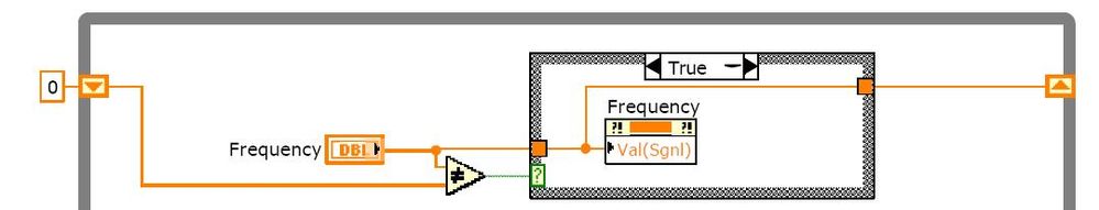
In this case to write the value to the control called "Frequency", I have a variable shared 'f' that is written in the other VI where all data entries will be implemented. Then in the "Frequency" control properties, I bound the control to this variable shared 'f' And the using the structure of the image I managed to do the SIT react against changes in the 'Frequency' control and apply the new value to the Simulink Simulation.
The truth is that I still do not understand why the SIT does not recognize the change in the control without using all this stuff, but it's working now.
So could you clarify my doubts about this issue and the problem with the two panels with the SIT fron, that would be great.
Thank you best regards &,.
Jose
Tags: NI Hardware
Similar Questions
-
Hello!
I'm currently testing a simulink model in veristand. I import the model into veristand and deploy code to the target. The model seems to work properly. But I want to measure the time used for the model, I wonder so if it is possible to have a record with tracetoolkit.
Someone has an idea?
Thank you...
Check out this Execution Trace Tool Custom device provided on the page modules VeriStand. Add this device to your system definition file to programmatically configure, start and stop traces of execution that are sent to the host.
You can examine these tracks to see approximately how long your model is complete by looking for the thread named after your model. For example, if your model is called sinewave, you should see a thread named sinewave_MODEL LOOP. To track the performance of your model, keeping in mind that there are a small amount of additional overhead in the loop of model before program us your model.
-
Veristand Simulink model initialization
VeriStand 2013 has now the ability to initialize the settings of the Simulink model (reference: signals and initial Conditions in a Simulink model mapping).
The question is: is it possible via API in LabVIEW calls? I would like the user to be able to select the name of the initialization file in my host code.
I have a temporary workaround to have the file name selected by the user copied to a temporary location / name defined in VeriStand System Explorer, but it is certainly not an elegant solution.
Currently, the only way to change the parameter values by default for a system definition is:
1. update the system definition to point to a different file.
2. switch to update the contents of the file that is already stated in the system definition.
#2 looks like the simpler approach recommended for your use case.
One thing that might make your solution a little easier would be to use the index function in the template parameter initialization file. What you can do is the following:
1. (optional) create. that various pattern files of calibration in advance you want to test. Name them sub1.txt, sub2.txt, etc. (or name them as you wish).
2 configure your system definition to point to a calibration of empty template file named Main.txt.
3. prior to deploying your system definition, change the main.txt file to add the following line (assuming that commas here because it's hard to type tabs in a web browser):
Subscript,c:\whatever\sub1.txt
You can also have multiple index files if you want to mix and match. Simply add extra lines.
The advantages of this approach are:
(a) you can easily use the pre-established model calibration files.
(b) you don't have to copy the files autour
(c) the write file you need to do before you deploy is very very simple.
-
Build the NMAKE error for simulink model
I spent by the procedure of how create the DLL of simulink models http://digital.ni.com/public.nsf/allkb/D70E74FDA37CD8E486257990000603A0 the and have not been able to successfully build the DLL for my model.
I installed Visual Studio 2008 and I can see the Relatime Veristand workshop added to matlab. However, I get the below error.
The system does not have the specified path.
"NMAKE: fatal error U1077: 'copy': code 0 x ' 1 ' back
Stop.
D:\users\f46123a\Desktop\Controls\Software\Models\Inputs\CabinTemp_NI_niVeriStand_rtw>echo the mark command returned an error of 2
The mark command returned an error of 2
D:\users\f46123a\Desktop\Controls\Software\Models\Inputs\CabinTemp_NI_niVeriStand_rtw>An_error_occurred_during_the_call_to_make
'An_error_occurred_during_the_call_to_make' is not recognized as an internal or external command
operable program or batch file.
# Time real workshop build procedure for model: 'CabinTemp_NI' aborted due to an error.Matlabe error window has the explanation, as shown below:
It seems that the build process could not locate some utilities (e.g. do,
compiler, linker, etc.). Please check your environment variables path and tool
are correct. You should be able to run the make command:
.\CabinTemp_NI.bat
at an MS-DOS command prompt in the directory:
D:\users\f46123a\Desktop\Controls\Software\Models\Inputs\CabinTemp_NI_niVeriStand_rtw
Currently, this method generates the following error message:D:\users\f46123a\Desktop\Controls\Software\Models\Inputs\CabinTemp_NI_niVeriStand_rtw>set MATLAB = c: \ Program Files (x 86) \MATLAB\R2010bSP1
D:\users\f46123a\Desktop\Controls\Software\Models\Inputs\CabinTemp_NI_niVeriStand_rtw>set MSVCDir = c: Program Files files (x 86) \microsoft visual studio 9.0\VC
' D:\users\f46123a\Desktop\Controls\Software\Models\Inputs\CabinTemp_NI_niVeriStand_rtw>"C:\Program files (x 86) \MATLAB\R2010bSP1\rtw\bin\win32\envcheck" INCLUDE "c:\program files (x 86) \microsoft visual studio 9.0\VC\include".
D:\users\f46123a\Desktop\Controls\Software\Models\Inputs\CabinTemp_NI_niVeriStand_rtw>if errorlevel 1 goto vcvars32
D:\users\f46123a\Desktop\Controls\Software\Models\Inputs\CabinTemp_NI_niVeriStand_rtw>set VSINSTALLDIR = c: Program Files files (x 86) \microsoft visual studio 9.0
D:\users\f46123a\Desktop\Controls\Software\Models\Inputs\CabinTemp_NI_niVeriStand_rtw>set VCINSTALLDIR = c: Program Files files (x 86) \microsoft visual studio 9.0\VC
D:\users\f46123a\Desktop\Controls\Software\Models\Inputs\CabinTemp_NI_niVeriStand_rtw>set FrameworkSDKDir = c: Program Files files (x 86) \microsoft visual studio 9.0\SDK\v3.5
D:\users\f46123a\Desktop\Controls\Software\Models\Inputs\CabinTemp_NI_niVeriStand_rtw>call "C:\Program Files (x86)\MATLAB\R2010bSP1\toolbox\rtw\rtw\private\vcvars32_900.bat.
Definition of conducive using Microsoft Visual Studio 2008
(If you have another version of Visual Studio or Visual C++ installed and wish
to use command line tools, run vcvars32.bat to this version.)I have the good set compiler but I'm not able to solve this error. I've also attached the text file that contains the log for the build process.
Can someone help me with this please? where am I wrong or what am I doing wrong?
Thank you
Hi Jigar273,
(1) have you configured MATLAB to use the compiler to MSVC ++ 2008? If not, then just type mex - configure in the MATLAB command window and follow the printed instructions.
(2) open Windows command prompt and type % NIVERISTAND_ROOT, and then press ENTER. The call to this environment variable returns C:\VeriStand? If this is not the case, then please add this environment with the value of C:\VeriStand variable to your system and restart the PC. To do this, follow the instructions as described in the link: http://support.microsoft.com/kb/310519
-
I would like to be able to programmatically change the time step, a Simulink model uses when it is called by the model Interface Toolkit LabVIEW. The time step is a template parameter or a signal of model. Is this possible to do?
It is not possible. The timestep for the model is fixed and compiled in the model. You can do things like relaxation model subsystems based on a value entry or event within the model.
-
What is the best approach for the upgrade of the DSC-LV2012/LV7.1/DSC static variable tags in several screws running on several platforms? Our system is made up of about 5 PC running Windows 2000/LV7.1 DURATION, the more a PLC and a PDC running XP/SP3/LV2012. About 3 PC publish information from the sensor through tags on the local network to the PDC. Only the main command is currently being upgraded. Basic questions:
1. the other computers running RTÉ 7.1 (with labels) will be able to communicate with the PDC running 2012 (shared variables)?
2. is it necessary for conversion of tags shared variables, or the deprecated legacy tag screws of LV7.1 work in LV2012?
3 all of the main controllers will be screw must be integrated in a project in order to use shared variables?
4 is the only way to do it is to find all the tags and replace them with elements of shared variable?
Thank you in advance with all the information and advice!
lb
Hello lb.
Datasockets are the common middle only my knowledge between versions, so apart from the upgrade to the same version, they will probably be your best bet.
-
Problem with Simulink model dll running on target RT
Hello!
At the beginning I specify software and hardware that I use:
LabVIEW 8.5
Simulation Interface Toolkit 4.0.0
Microsoft Visual C++ 6.0
MATLAB 7.4.0 (R2007a)
NEITHER cRIO-9014
At first, I did a simple Simulink model (Sine generator, gain and an outdoor sink), then I started with vi empty and abandoned command digital for the gain and the waveform for the sine table. I grabbed SIT Connection Manager and that you have chosen Simulation Environment case. Then I loaded a template file, the mapped controls and indicators. Everything worked like a charm. Problems started when I tried to turn on an RT target. Maybe I'll explain step by step what I did and after the error at the end.
1. I created a dll from a MATLAB simulink model file. I selected in time real workshop one C language and target to "nidll.tlc". The I compiled without error.
2. I entered LabVIEW SIT Connection Manager and changed the host execution target in real time. File browser has popped up and I selected the dll already made my template file.
3. in Add target devices on window, I chose 'existing or peripheral target' and I chose in the other menu in time real CompactRIO. There was my compactrio system, I chose it and LabVIEW began to search for devices.
4. after that, I clicked the "Ok" button in the SIT connection manager.
5. I clicked the run button before my vi file panel and LabVIEW began deployment.
And here the deployment failed with the following error message:
Deployment of 192.168.1.2 (parameters target successfully deployed)
Deployment compatOpenFileOperation.vi (5.35 K)
Deployment of SIT copies values from Replay on Inports.vi (10,96 K)
Deployment of SIT expand newspapers Signal Names.vi (4.99 K)
Deployment of SIT PostOutputs.vi
Could not download SIT PostOutputs.vi
LabVIEW: Unable to load the shared library SITs.out ostOutputs:E on the target RT device.
I tried to do everything once again and got a little different error message:
Deployment of 192.168.1.2 (parameters target successfully deployed)
Deployment of common access to specific Path.vi (22.25 K) path
Deployment of SIT runtime DLL query.vi
Could not download SIT runtime DLL query.vi
LabVIEW: Unable to load the shared library SITs.out:TaskRunTimeInfo:E on the device target RT.What I am doing wrong? Any ideas? I will be extremely grateful for the ideas!

Best regards
Pawel
SIT 4.0 does not support VxWorks targets as your cRIO. SIT 5.0 was the first version to have any level of support for this.
I would recommend contacting support to discuss a possible workaround solution. If they have questions, you can reference this post on the forum and they can contact me. I hope this helps.
-
How to interface a simple way using LabVIEW 2009 simulink model and SIT?
Hello
I finally found a way to use a template simulink with LabVIEW and the Toolbox to SIT, but I'm not satisfied.
If you have any suggestions, the link of resource that I missed, please do not hesitate to answer
Note that I do not know much about simulink, so that is my question seems stupid, let me know what

Software configuration
OS: Windows (not an RT target)
LabVIEW 2009
SIT 2009
question 1: interfacing the model DLL (mapping considerations) with a driver VI
We have created a model of DLL by using the 'Workshop in real time' tab in simulink.
In LabVIEW, launch us the tool 'SIT connection manager' and try to use the DLL with a driver VI by mapping the e/s model for screw/lights orders.
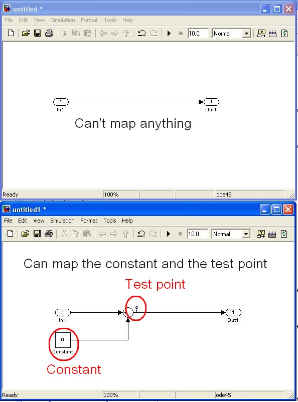
The fact is that I fail to connect to my controls/indicators VI/o model because they do not appear in the mapping dialog box.
The simulink single objects that I managed to map are "constant" and "test points" while I need to edit the template simulink itself (example below)
Are in e/s model, not considered as part of the parameters of the model? (this could make sense because the mapping says in fact that it operates on "model parameters")
Is it possible to link the IO model VI commands/lights?
Note:
-the "configure HW i/o mapping" dialog box allows me to map model e/s with e/s HW...
-The examples also use these "constant" and "test points".
2nd question: use of direct screw SIT
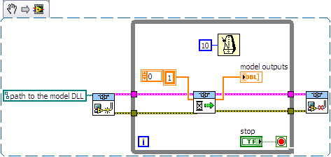
I tried to use the DLL directly with the screws SIT (code example below)
This kind of code works well on another project (target of 8.0/RT LV) but not on the current project (LV 2009/Windows)
The second stage of the model never ends:
-0-index of the loop works as expected (model doing its job).
-index of the loop 1 starts normally, but execution is stuck in the 'SIT scheduler.vi.
Then I have no choice that to kill LabVIEW ("Reset screws" windows appear if I try to stop/close them).
Is there a reason that I do not see what explains this behavior?
Thanks for reading.
Any help appreciated.
Kind regards
Hello
I spent some time analyzing the VI driver as you suggested.
Here are my findings.
Question 1: the SIT connection manager does not pass to the model SW controls/indicators. Only, it allows the user map HW AIs/AOs.
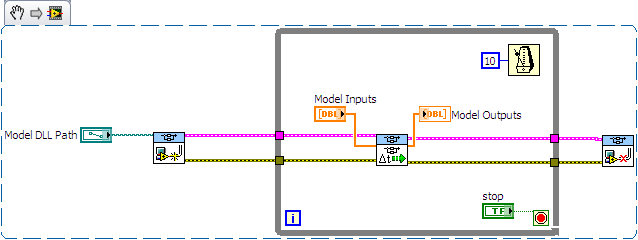
The only solution I found (to have a SW - for example a shared variable - object that is mapped to an input/output model) is to customize the VI driver that is scripted by the SIT Connection Manager ("_Base
rate Loop.vi" in the flat sequence structure named "read code") Question 2: after spending some time in the VI driver, it seems that the VI to call right is not 'SIT scheduler.vi' but 'If SIT take model no time' (which uses the other as a Subvi)
My conclusions are correct? If I use the API in the wrong way, please let me know.
Kind regards
-
Mapping to the signals and initial Conditions in a simulink model
Hello world. I am pretty competent with old Simulation Interface Toolkit (SIT) and I am moving to Veristand. I have some basic questions that I think that know the answer, but who want to do some checks.
First of all, when you map signals, such as the output of a block check, is it possible to make them available for mapping other that mark the test points? At the bottom of this page, it is a bit ambiguous, but it seems to suggest that if I disable optimization option will appear any sudden without needing me to mark all test points. The I am referring to something specific is the following, "Certain optimizations that you activate in Simulink can make a not available in NI VeriStand signal. You can disable these options for the entire model to all the signals available to probe, but the model memory footprint increases accordingly. Alternatively, you can mark individual signals as test points in Simulink to maintain a very reduced memory footprint by keeping test-point available signals to probe. »
My second question is in what regards the "initial condition" parameters There was a problem in SIT (although National Instruments has not agree with me at the time that it was a problem), where you can map the controls to these settings, but at the moment where you have been given access to the model, the initialize function had already been called, which means that your maps were useless. I see that I can still map to these settings in Veristand, and I wonder if the same problem exists. I'm not quite to the point where I can start trying to change these but I'm hoping to avoid the days of debugging, I lost on this whole by learning to SIT.
As a follow-up on the second question, to SIT, I could find the C code (located in nidll_main.c) that was called whenever the 'play' button and add a second call to the initialize function. So let me change the initial conditions without recompiling my entire model which, in my case, would be unworkable. If this problem still someone was able to implement a similar solution?
Optimization, you can disable in Simulink (TM) I believe is called Signal storage reuse. To my knowledge you either need to use individual test on son points, or you must disable overall re-use of storage of signal for your model.
Regarding the second question, the question still exists in NI VeriStand. This is something that we are aware of what we expect to address in a future version of NI VeriStand. The workaround you describe might possibly work if you do enough digging in the C code. Currently VeriStand charge and then initializes the model at the same time, and initializing code can read the values of model parameter. If you check out this code and move to the first call to the main function of the calendar, you could allow for the adjustment of the parameters of the model before the model starts.
-
Problem starting on several Satellite C50 - C70 models
The members of the forum and Toshiba, Hello
Recently, I sold several laptop Toshiba Satellite C50-70 and Satellite Pro series.
With most of them, I knew starting problems.
When turn on/off the laptop, I see the Toshiba Logo and then nothing happens.
I have to turn it on and turn it on again so he can start on Windows. (7 or 8.1)Sometimes, I have to power OFF / ON several times.
What I see is that the NumLock light does nothing. If the system starts, I see this LED flashes on / off 2 times. So, I can see on forehand if the laptop to boot Windows or hangs at the Toshiba Logo.
Anyone having the same problems?
I put t know if anyone has had this problem but I guess that if the books are new and covered under the Toshiba warranty, you must contact the maintainer authorized Toshiba in your country to check the material part.
The Toshiba start screen freeze means that the POST (power on self-test) could not be transmitted correctly and it is especially a sign of hardware malfunction.
-
Create several screws using a loop for
Hello
I am still fairly new to LabVIEW, that this issue might be easy for you guys here...
I'm going to simplify what I'm doing.
I have two digital controllers who act as the rows and columns of a matrix.
I would take those figures of these two controllers and use them to create a matrix of a certain image.
Example:
The controller of lines is 3, and columns controller has 4.
Using these numbers, I would like that the final result to show a certain image (say, a cube) on a matrix of 3 times 4.
Let's say that the image is an X, then the end result should be:
XXXX
XXXX
XXXX
I think I should use a double loop for (one inside the other, obviously), and I should also create the 'position' property to display each image of the cube to its rightful place.
The problem is that I don't know how to CREATE the images over and over again, while being able to control the position of each property.
Any help would be GREATLY appreciated!
These small 'boxes' (key word being little) are simply called under screws. Express vIs are large blue abominations that take valuable real estate and are intended to make life easier for you.
This is the VI recorded in LV8.6
-
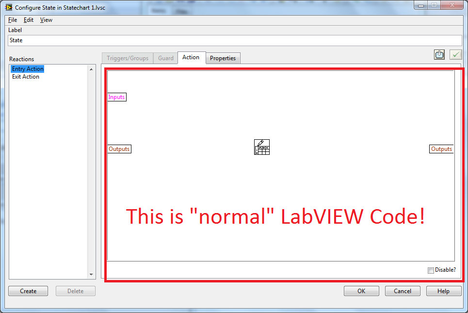
ISI t possible to use several screws with state diagram module
Hello
I'm doing a request using the module state diagram, and I have to use at least for VI I developed. I have problems when I want to set the entries before creating different States. My VI have stop buttons and the e/s I need to use. I have the same problem with the outputs. Because I can not set the input/output (type moore machine) I can't nor define the guards and actions that the state machine must fallow.
You have an idea if we can use several VI with this module or do I have to use the good old box + all state machine technique.
Thank you.
Of course, this is possible.
hope this helps,
Norbert
-
creating a dll from simulink model labview requires visual studio
I asked the same question on the forums of Simulink, but maybe someone here has the answer:
I am trying to do this here:
http://zone.NI.com/DevZone/CDA/tut/p/ID/3447
However, I get the following errors of the workshop of Simulink in real-time:
Error of construction target real-time Workshop for block "SensorCAN_sfcn". MATLAB error message:
With the help of the error ==> setup_for_visual > LocIssueMSDevError at 324
Invalid value for the MSDevDir or PublicAssemblies% environment variable.
The setting is: "
You can check the setting by checking the existence of:
% DevEnvDir%\... \tools\vsvars32.bat (for Visual C/C++ 7.1)
% MSDevDir%\...... \vc98\bin\vcvars32.bat (for Visual C/C++ 6.0)
% DevEnvDir%\... \tools\vsvars32.bat (for Visual C/C++ 8.0)I don't use Visual c, few do what programming was made in Borland Builder or with gcc command line. Is there a way to make simulink for a different dev environment? Or this process requires Visual C?
Hey,.
It depends on what version of SIT you use.
With SIT 5.0 and later versions you can use a free compiler as described here:
http://digital.NI.com/public.nsf/allkb/AAD15283A1F051A1862574F000744DBD?OpenDocument
With earlier versions, you need VS. 2006.
Hope this helps,
Christian
-
Several data definition EBS models
Hello
My problem is the following;
I have a definition of data with 2 models in EBS 11i, say T1 and T2. I want to do is display the output of the T1 when I run my program simultaneously and burst T2 in a file. The problem is, there seems to be no way to define T1 as the model by default for the program to use display T2 and bursts T2.
I feel I'm missing something. Notice to lovers?
KofiYou can try.
Access
-Concurrent-> programs > system administration
Ask the program. Choose update-> setting-> T1 choose and register on-siteNow, when you run this CP you should have by default like T1 only.
-
How to create a DLL from a .mdl file model to use on veristand simulink
Hi all
I want to create a .dll file from a simulink model .mdl file. I created a simple "Sample.mdl" file that adds two entries and gives the result.
Before you build the .dll, I tried to run file .mdl veristand. Here, I got the below error.
Method 1: I tried to create a DLL out of it by going to the Simulation-> settings-> workshop in real-time. Here I tried to change the target file system to NIVeriStand.tlc, but I'm not able to see that in the system target file browser dialog box. Can anyone tell me the reason behind that.
Then I tried method 2.
Method 2: I created this .mdl C code using grt.tlc in the Simulation-> settings-> workshop in real-time. I clicked on 'build' button, then he created C equivalent for this code. Using Microsoft visual C++, I tried to generate the .dll file, but I have the following errors.
Can someone help me on this please. My goal is to launch this model with veristand eithor in.dll or .mdl file format
Thank you
Herald
Maybe you are looking for
-
I have problems with the battery of my M305-S4826
In my computer, the battery light flashes, and hovering over the windows, the power icon indicates that the battery is not detected wath could be
-
Image is like a photo negative
I'm on a Genesis of bike E 2nd with Cricket The image is reversed, like a photo where black is white and vice versa. I don't know how it happened.
-
I am trying to configure mode pulse on Agilent 33120 A using RS - 232. I finally understood that the relevant screw on instrument driver does NOT support the 33120A! Anyone have any ideas?
-
Always download blocked by the "security settings".
Whenever I try to download an update or a program, told me that "the security of my computer settings do not allow" to be downloaded. I tried to eliminate my security settings altogether, but which does not succeed, and I don't know how to solve thi
-
HelloI recently started getting a problem has occurred to the bottom of my laptop and also with sleep/hibinate function. I made sure all updates are updated via HP support Assistant.I also disabled the quick start of the function that was identified