signal average and relaxation
I know how to program to acquire the signal. But I donot know average and raise my signal as a work of the oscilloscope? What do I have to use "average dc - rms VI" to calculate the rms dc values and/or a waveform of input on average? In oscilliscope, I can choose average 16,32, 64... 512. how to achieve here? There is also a filter of bandwidth in the scope.
The trigger is nothing but looking for a crossing of a certain level. You can use a simple top or a less than to find that. On average, as a scope, you must acquire the signal several times. You can then perform the average for each data point in a loop FOR.
Tags: NI Software
Similar Questions
-
FIRST HP: Deviation average and a discrete random Variable probability Distribution
Hello
Can comeon please help me with the calculation of the average and standard deviation of the discreet following random variable probability distribution.
* k = 0.14
I would like to the average and the standard deviation of the number of people per car.
I used the 'statistics 1 VAR App' and I entered in the following:
When I click on 'Statistics', the following text is displayed:
Responses (rounded to two decimal places) for the mean and the standard deviation should be:
Average = 3.67
SD = 1.31
It seems that the statistical calculations are based on the column "D1" only.
Is someone can please show me how I can put the statistical calculations to include the data in the columns "D1" and "D2"?
Thank you
Arthur
I solved my problem.
I read the pdf document "HP first AP statistics Summer Institute ' and it explains how to use the app from Var Satatistics 1 more in detail.
Concerning
Arthur
-
PCI data acquisition and Signal controller and SM Bus controller drivers are not installed
My laptop is Toshiba satellite L305 with Intel Pentium (R) Dual CPU T3200 2 GHz / 2 GHz.
Rescently that he has been upgraded to Windows Vista Ultimate Edition, 32-bit operating system. Since then, my USB device wireless to connect to the internet is not worked. The Device Manager displays a yellow! Select this option for PCI Data Acquisition and Signal controller and the Bus controller. The details for the two area said that pilots are not kept.
How can I get these drivers. I'll appreciate your help, thank you.
Carlos
http://www.CSD.Toshiba.com/cgi-bin/TAIS/support/JSP/home.jsp
Toshiba support at the above link
http://www.CSD.Toshiba.com/cgi-bin/TAIS/support/JSP/home.jsp?NAV=download
Toshiba Driver download at the link above
http://laptopforums.Toshiba.com/
Toshiba laptop Forums at the link above
~~~~~~~~~~~~~~~~~~~~~~~~~~~~~~~~~~~~~~~~~~~~~~~~~~~~~~~~~
Access the site of the manufacturer of your laptop to the link above > drivers and downloads Section > key in your model number > look for the latest Vista drivers > download/install them.
The computer you are using now if you have an Internet connection with the other > download / save drivers > copy them into Flash Drive > transfer / install on another computer/laptop.
See you soon.
Mick Murphy - Microsoft partner
-
to fill the gaps with value of lead and the delay and make average and the gap between earned
Thanks in advance
I have table as below
What I need is to fill the gaps with value of lead and the delay and make average and the gap between the valuesID TYPE NUM NAME BEG_MP END_MP VALUE 10001103N 3 1190001 WST 0.000 0.220 10001103N 3 1190002 WST 0.220 0.440 10001103N 3 1190003 WST 0.440 0.820 12800 10001103N 3 1190003 WST 0.820 1.180 12800 10001103N 3 1190004 WST 1.180 1.220 10001103N 3 1190004 WST 1.220 1.300 10001103N 3 1190005 WST 1.300 1.420 14800 10001103N 3 1190005 WST 1.420 1.550 14800 10001103N 3 1190006 WST 1.550 2.030 10001103N 3 1190006 WST 2.030 2.660 10001103N 3 1190007 WST 2.660 2.780
ID          TYPE     NUM     NAME     BEG_MP     END_MP     VALUE
10001103N     3     1190001     WST     0.000     0.220     12800 ---> Lag value
10001103N     3     1190002     WST     0.220     0.440     12800 ---> Lag Value
10001103N     3     1190003     WST     0.440     0.820     12800
10001103N     3     1190003     WST     0.820     1.180     12800
10001103N     3     1190004     WST     1.180     1.220     13800 ---> Avg(12800,14800)
10001103N     3     1190004     WST     1.220     1.300     13800 ---> Avg(12800,14800)
10001103N     3     1190005     WST     1.300     1.420     14800
10001103N     3     1190005     WST     1.420     1.550     14800
10001103N     3     1190006     WST     1.550     2.030     14800 ---> Lead Value
10001103N     3     1190006     WST     2.030     2.660     14800 ---> Lead Value
10001103N     3     1190007     WST     2.660     2.780     14800 ---> Lead Value
create table AVG_TABLE ( ID VARCHAR2(20), TYPE NUMBER, NUM NUMBER, NAME VARCHAR2(10), VALUE NUMBER, BEG_MP NUMBER(6,3), END_MP NUMBER(6,3) ) ; insert into AVG_TABLE (ID, TYPE, NUM, NAME, VALUE, BEG_MP, END_MP) values ('10001103N', 3, 1190001, 'WST', null, 0, .22); insert into AVG_TABLE (ID, TYPE, NUM, NAME, VALUE, BEG_MP, END_MP) values ('10001103N', 3, 1190002, 'WST', null, .22, .44); insert into AVG_TABLE (ID, TYPE, NUM, NAME, VALUE, BEG_MP, END_MP) values ('10001103N', 3, 1190003, 'WST', 12800, .44, .82); insert into AVG_TABLE (ID, TYPE, NUM, NAME, VALUE, BEG_MP, END_MP) values ('10001103N', 3, 1190003, 'WST', 12800, .82, 1.18); insert into AVG_TABLE (ID, TYPE, NUM, NAME, VALUE, BEG_MP, END_MP) values ('10001103N', 3, 1190004, 'WST', null, 1.18, 1.22); insert into AVG_TABLE (ID, TYPE, NUM, NAME, VALUE, BEG_MP, END_MP) values ('10001103N', 3, 1190004, 'WST', null, 1.22, 1.3); insert into AVG_TABLE (ID, TYPE, NUM, NAME, VALUE, BEG_MP, END_MP) values ('10001103N', 3, 1190005, 'WST', 14800, 1.3, 1.42); insert into AVG_TABLE (ID, TYPE, NUM, NAME, VALUE, BEG_MP, END_MP) values ('10001103N', 3, 1190005, 'WST', 14800, 1.42, 1.55); insert into AVG_TABLE (ID, TYPE, NUM, NAME, VALUE, BEG_MP, END_MP) values ('10001103N', 3, 1190006, 'WST', null, 1.55, 2.03); insert into AVG_TABLE (ID, TYPE, NUM, NAME, VALUE, BEG_MP, END_MP) values ('10001103N', 3, 1190006, 'WST', null, 2.03, 2.66); insert into AVG_TABLE (ID, TYPE, NUM, NAME, VALUE, BEG_MP, END_MP) values ('10001103N', 3, 1190007, 'WST', null, 2.66, 2.78); commit;Hello
Use LEAD and LAG when you know exactly how far is the target line (for example, if you know the desired value is on the next row).
If you don't know exactly how far is the target line, then FIRST_VALUE and LAST_VALUE are more likely to be useful.WITH got_neighbors AS ( SELECT avg_table.* , LAST_VALUE (value IGNORE NULLS) OVER (ORDER BY beg_mp) AS prev_value , LAST_VALUE (value IGNORE NULLS) OVER (ORDER BY beg_mp DESC) AS next_value FROM avg_table ) SELECT id, type, num, name, beg_mp, end_mp , COALESCE ( value , ( NVL (prev_value, next_value) + NVL (next_value, prev_value) ) / 2 ) AS value FROM got_neighbors ORDER BY beg_mp to f ;Riedelme is correct: LAG LEAD (as well as FIRST_VALUE and LAST_VALUE) can return only the values that are there (or that you give as default values). This means that you can not solve this problem with these functions alone; you need something else (as NVL, above) to provide value when the function does not find it.
-
How to synchronize the start of IT and relaxation the Scan list (DAQmx Switch)
Hello
I want to measure samples of N to the AI0 of Council NI PXI 4461. The measurement starts on a rising edge of a digital triggering provided to the PFI0 of the same Board. The measure is configured with samples of N/2 pretrigged. So far, everything is under control...
Using an NI PXI 2567 Board, the signal applied at the entrance the 4461 (AI0) switches between a V2 and V1 signal. I would like to synchronize the switch between the two signals with the trigger signal applied to the input of the PFI0 Governing Council 4461. In order to obtain samples of N/2 of V1 and V2 samples N/2. Synchronization of 1 to 5 ms would suffice!
My question is how to synchronize the start of acquisition of AI pretrigged of 4461 with the switch control given by the Council of 2567?
Thank you in advance for your help...
PS: the configuration of the system is:
-LabView 8.5
-Chassis PXI-1044
PXI-4461 on slot 2
Module 4-slot PXI-2567
Hi Frederic,.
I came back to this recently and used the following examples to run the desired synchronization.
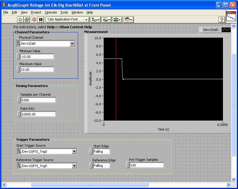
PXI-4461: Acq & graph tension-Int Clk - dig Start & Ref .vi
Samples per channel = 1000
Rate (Hz) = 10000.00
Start the trigger Source = / [name of the instrument DAQmx] / PXI_Trig0
Onboard start = fall
Reference Source Trigger = DAQmx Device Name] / PXI_Trig0
Reference edge = fall
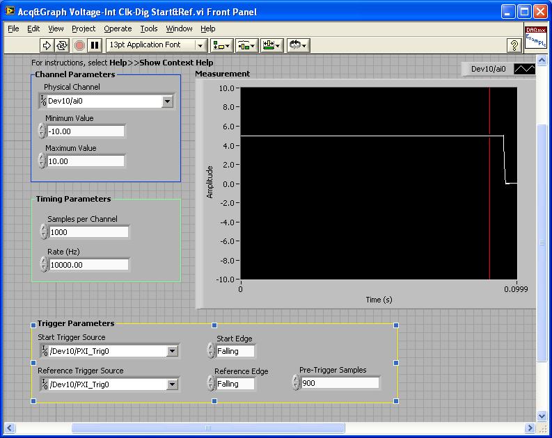
Trigger samples = Variable (100, 500, 900)
PXI-2567: Switch Scaning-SW Trigger.vi
Advance the output terminal full = / [name of the instrument DAQmx] / PXI_Trig0
Scan list = / [name of the instrument DAQmx] / ch0-> com0.
Scan list = / [name of the instrument DAQmx] / ch1-> com1;
Hardware configuration:
The PXI-2567 module controls an external relay that switches between the voltage of 5 V on ch0 and ch1 0 V.
The PXI-4461 connects to the COM of the external relay and therefore reads 5V when ch0 is connected; 0 v when ch1 is connected.
Procedure: The above examples are used in the following procedure.
1. run the PXI-4461 VI. A start trigger (falling edge) is necessary to start collecting samples before firing.
2. launch the module, PXI - 2567 VI. When ch0 is initially (and immediately) on com0, a trigger is sent to PXI_Trig0. The PXI-4461 will begin to acquire samples before firing.
3. - click on the "Connect to the next" button on the front of the PXI - 2567 VI module. This sends a trigger to entry software for the PXI-2567 module and the transitions of the scan for ch1-> com1 list. Once the PXI-2567 module remains (debounced), advanced complete relaxation is sent on PXI_Trig0 for the PXI-4461. The PXI-4461 will begin to acquire samples after outbreak.
Note: Instead of the trigger of the software entry, an external input trigger can be used (e.g. PXI_Trig1).
Results:
> Before instant release of samples = 100
Delay is caused by the time of actuation of external relay.
> Before instant release of samples = 500
Delay is caused by the time of actuation of external relay.
> Before instant release of samples = 900
Delay is caused by the time of actuation of external relay.
I hope that the attached screws and the explanation above helps you and/or other customers who have this problem.
Best regards
Chad Erickson
Switch Product Support Engineer
NOR - USA
-
Signal strength and range of the latest wifi routers
I have a big house, with my router (BT home hub) in a wiring closet in a laundry room. The House is wired for ethernet and my current Wi - Fi, a Netgear WPN802, is placed at the best discreet place in the House. It is quite visible from everywhere in the House, the signal is quite low in some places.
If I replace it with a common Netgear router, switched to AP mode, I see a significant improvement in the strength of signal and the beach? Smartphones, tablets and streaming music boxes (Sonos) are the usual wifi customers.
In general, with one exception, hand-off is controlled by the device. On devices where the roaming aggressiveness can be adjusted, usually of the laptops and PC with Wi - Fi cards, it is sometimes possible to do hand-off low impact, but it is often neither transparent nor without interruption. I walk often so, personally, that this is not a matter of my house with my laptop streaming.
However, smartphones often do not have adjustable settings of roaming aggressiveness, but it is precisely the devices with which we want to transfer transparent. My old iPhone 5 was terrible to homelessness at home and at work.
If you install a second WAP in your House, don't expect transparent transfers. But, as I said, it's usually to the device.
I talked to an exception almost, and perhaps two. One is that there is a connection Wi - Fi standard 802.11r called which rudder hand fast shipment. I don't think that any consumer connection Wi - Fi gear to implement. Two is that Ubiquiti Networks offers an exclusive feature called discount zero where several Ubiquiti APs can work together in the hand-off a device between them. I don't know which of their products offer this feature, but my guess is that they are not cheap. The disadvantage of this feature is that all points of access must use the same channel Wi - Fi (they do all access points appear as an access point). It is not so good, if you have many Wi - Fi devices and need a lot of bandwidth. It is a compromise between speed and reliability.
I would recommend that you try one of the higher end Netgears with external antennas. If you are happy with your current router and only need an AP, consider the EX7000. It is marketed as a wireless extension, but it is also usable as a wired access point. It'll be cheaper than the R7000. But if you want to improve your router, then the R7000 is an excellent choice. I have one and it covers almost my entire House, 2 storeys.
-
LTE application: Signal PSS and EU synchronization problem
Just as I suspected, samples received on the receiver side are only cross correlated with the PSS sequence (PCI mod 3) = 0, this is the reason why the synchronization does not work when the eNB transmits with a (PCI mod 3) 0. The PSS sequence (PCI mod 3) = 0 is integrated as a time fixed signal of the domain in the FIR filters although (the two who treats I and rated a Q of the received signal handling complex). To change this and to implement a different sequence of PSS, should open the basic FIR blocks Xilinx generator and change the sequence.
I got some guys from support LabVIEW Communication an updated version of the "LTE Cross Correlation.gcdl" function that implements a selective control for the value (PCI mod 3) and seems to change the PSS sequence within blocks of FIR. I post here if someone has the same problem. Although I have not tried myself yet.
-
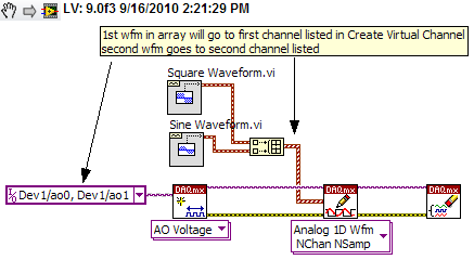
Using Labview and PXI-4461, how can I AO0 output Signal Square and AO1 output waveform
I am using PXI-4461 and Labview, boredom, generating 2 signals simultaneously.
How can I get AO0 out square and exit AO1 SignWave?
Help, please. (The example Code would be nice)
Thank you.
Create two signals and make a table with them. Use DAQmx Create Virtual Channel to create two channels. First waveform will be sent to the first string, second waveform on the second channel.
I understand not all as calendar, clock frequency, amplitude, trigger and other parameters. You can add these things. This is just a basic example.
-
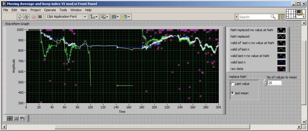
Moving average and keep indexing
Hi all
Many members share so nice VI for the execution of moving average. But if the measure deliver (NaN) it will be a problem in this case, specifically. When
the processing of the data is in real time mode. So please can help me to handle this.
Here I try to do, its works well, but when I insert it to the acquisition in time real and treatment he puts a lot of problems.
Thank you.
some methods more...
What are you going to measure? Just curious

-
How data for chart FPGA of DMA Fifo and relaxation
Have a design Question here:
IM using a FIFO DMA here at the flow of data from the target to the host. Side host, I was using the FIFO read Functinon, converting to Dynamic Data and display in a chart in 'real time '. Pretty easy.
However, I would like to make it more functional. The incoming signal is essentially a square wave. I want to trigger on a rising edge, and then graphic permanently the result in the table. I tried to add that 'trigger and Gate' express Vi, but its uneven (see attached photo).
I am on the right track, or should it be done differently? I was not able to find specific examples for this. I think Im getting messed up because my data are read from the FIFO as a table 1 d, 5,000 items at a time. All of the other examples I've found just show the signals that are generated on the host computer already at a fixed frequency.
Thank you!!!
Bones349,
Hello! Some ideas/questions
1.), you could make a detection of edges in your FPGA, saving you a lot of treatment because no no need to spend no relevant data until the host code.
(2.) what you're doing in splitting the numbers before their conversion to the type of dynamic data? I'm not surw what happens there. You can use a data type of waveform instead, because she would have an element of time to your data.
3.) 5000 incidentally both through your FIFO would be fine.
-
Signal noisy and shielding techniques
Hi all
I'm having a problem with excessive noise on one of the signals in my test system.
The signal source is a third party device (interface to a sensor box) which produces a 0 - 1.0V signal proportional to the signal output. The signal is connected to a box distribution, then on my NI DAQ device via a Terminal SCB68. I use differential inputs.
As far as I know all the armor is correct. I know that it would be ideal to attach the chassis ground to the mass of the signal at the source, but it is not possible. The chassis of the signal source is not based, so there should not be a current loop in armor.
For a typical signal, I get about 20 mv (peak-to-peak) of higher frequency (> 100 Hz) noise and > 200 mV lower frequency noise ~ 20 Hz.
I have not been able to isolate the source of noise or to reduce the noise all additional levels. The lower frequency noise consists mainly of not sinusoidal noise peaks.
A wiring diagram is attached. I have the shield related to a 10 megaohm resistor that is connected to the Terminal GND of AI. I know it is different than what is recommended in the documentation, but I read other resources recommended in this regard. If I remove the resistance, noise doubles.
Thanks for your time.

1 if the signal is soemwhere Earth, then you don't have a differential signal. Although any difference in potential between the soil in the area of distribution of the signal and the SCB68 may appear as if it is part of the signal connected to the - entry. Do not put earth it or not use the setting differential input.
2 see 1.
3 OK. One end of the floating shield often helps.
I fear that ground in the distribution of signal box can be part of the problem. What was the reason for making this connection? Why here rather than at one end or the other or no ground at all?
What is the source of signal? What kind of sensor? How many channels will you measure?
Lynn
-
Problem when the PWM signal combinning and analog signal TOGETHER!
Hello everyone,
first I DAQmx 6212, and I need to run the water pump small (9V - 16V) that should be driven by a PWM signal; I also have a motor (5V - 13V) for a water supply which must be controlled by an analog signal and it has built in a force feedback potentiometer, I logged onto this potentiometer correction + 5V the DAQmx and used the output voltage of the third extremety as a value to diagnose to know the position of the engine.
My VI shows:
1 is a normal meter production to create my PWMout signal.
2 is an analog input, I use it as a PWMin to the LabVIEW to diagnose what is happenning in my pump water through the cycle and frequency.
3 is an entry of the third extremety of the analog potentiometer.
4 is an analog output that I used as power supply of the motor valve and I used an AC/DC amplifier for aplify signal the DAQmx and the motor road, between the two (3. 4.) I made a comeback with a few calculations, I had a P-controller to know the real position of the engine valve.
My problem:
When setting to 1. and 2. in the same VI only, I get an own PWM output with no problem.
also with 3. and 4. in the same VI only i can control the motor valve without any problem.
but when I put all these 4 set found in the attached VI, I have a problem as the engine valve turn continuously without stopping even if I change the position of the valve between 0 and 100%, I should mention that I see a PWM normal outside a signal on my oscilloscope, another thing to delete one of (1 or 2) and run the engine valve VI works fine without any problems.
so this my problem, if you can think of any solution please let me know.
Thanks in advance for your help.
Kind regards
Caliente
Here's your VI, slightly modified so the two analog inputs belong to the same task. This if only for purposes of illustration, I him have not tested. You will still need to do some debugging.
While changing your VI, I noticed another potential problem with your original configuration. You have configured the two tasks of AI for the same frequency, but read you 10000 samples of one of them and only 100 samples from the other (and throw it most of it). Data acquisition data are buffered, and if you read as fast as you acquire, the buffer fills eventually. If you read 10,000 samples of a channel, and the other channel acquires at the same rate, then when you read from the second channel you will get old stale data or an error full buffer.
-
Multiplexing of signals microvolt and conditioning of the right signals
Hello
We have 22 signals in our system. We must be able to measure any subset of these 22 signals. Usually, we carry out a number of measures IV 4points of separate devices on a SUT (sample to be analyzed). Two of the 22 signals may represent the pair of voltage measure 4-point IV, depending on how it was KNOWN is bonded. The level of the signal of tensions is in the 100s in the uV range and I need a precision as much as possible, so the unit or same sup - uV numbers. So far, we had all the 22 signals connected to a box (selfmade) acting as a distribution point, where a connector (SMB) is available for each signal. We then manually choose which two of the 22 that signals will be connected to a differential amplifier silent instrumentation (also selfbuilt), according to it was KNOWN patterns of liaison. The amplifier with a gain of typically 1000, returns the signal to an acquisition card. The current (excitation) is read separately.
There is a problem with that. We need to manually switch the connectors in the distribution box to select a different device on it was KNOWN and flows to the amplifier. This is not good for a number of reasons that I can't go here.
Therefore, I would like to multiplex these 22 signals to several outputs (for future scalability) who will be wired for the conditioning of signals. There is no manual connection/disconnection of these signals in this way. The first question is: can a matrix switch or multiplexer be used to route signals reliable microvolt? If so, then what kind: electromechanical, Reed relay or a transistor? Is the thermal EMF in the specifications of multiplexer/matrix relay just a lag, or is - that noise?
The second question is: what card/signal acquisition solution (so no selfmade equipment and legacy) products OR only using the same line that the matrix/mux can reach 1uV accuracy of treatment? For us, offset offset is not a problem since we measure the device in 2 quadrants and later cancel it in the software but the noise (and get the accuracy) is important. Our amplifier has a background noise of 3nV/sqrtHz and a bandwidth of 15 kHz. The system to replace must be comparable. I have the choice between:
- the SCXI based ones, instrumentation isolation (4ch) 1121 or 1122 amplifier modules (16 channels), with a ground noise that I calculate 20 and 30nV/sqrtHz respectively. They already have some functions of multiplexing btw.
- the PXI 628 x with a background noise that I calculate through 10nV/sqrtHz
- the PXI 446 x with the noise floor low 8nV/sqrtHz as stated in the technical data sheet
Module 4-way universal 24-bit NI 9219, who works with 2 samples per second has a very low noise total, but at a very low sampling frequency and I can't consider comparable to what we have now. In addition, the system must be able to have a few kHz bandwidth for dynamic action in the future.
Y at - it any other ideas?
Greetings
Aleksandar Andreski
-
Frequency of an analogue signal measurement and noise reduction
Hello everyone.
I'm reading a flow rate sensor that generates output signal square whose frequency has a linear relationship with the flow rate and varies from 37 to 550 Hz. My hardware does not support playback of the frequency, so I have to calculate. What I ended up doing was reading signal every 1 millisecond (1000 Hz), taking two samples spread and store the value of the signal and the time during which it was read. Every 400 milliseconds, I loop over the data and know how many cycles have taken place and the time between the first and the last cycle, divide the number of cycles at this time here.
Here's a graph of the signal.

I never use software loops timed then performing operations of data acquisition as a general rule. He's many trendy on negative issues. And as you mentioned that you cannot run a timed loop faster than 1 kHz. You should go to the Help menu in the toolbar, then select search examples. Then you look up "continuous acq. It is best to leave all the details of the calendar to the data acquisition unit and just retrieve data from the buffer of data acquisition, then it is needed. I have your case I would recommend a sample equal to 6 kHz freq. That's more than 10 times your highest frequency. You can always update your data at intervals to 400msec. Your signal also looks good. I can't have a lot of noise in your signal. If my guess is that your software is not optimal. You should not get 120 Hz, so there is no flow. If you post we can take a look.
-
Annoying when beep signal lost and found
Help. Phone warning beep when lost signal and then again when signal back. Impossible to find anywhere in the settings to disable it.
Gets boring, we live in the space with bad reception sounds so far in home even though we are on wifi.
Someone knows how to fix this?
Thank you
Take a look at this post


Maybe you are looking for
-
Show only the time and a red relief
My watch does not show the clock face. If I press the bottom button, it will display the time and a symbol of red light.
-
How to make a click right a link included to record on my Android phone?
How can I simulate a "right click and save the target under ' on a link embedded in a web page? I am recording 2 videos, one is a demonstration of the product and the other is an Assembly and the installation of a product that I plan to buy. The vids
-
Whenever I visit a site (like craigslist) links I click on are highlighted (or turn from blue to purple) and saved the next time I visit your site, allowing the next person to see exactly what links I have chosen. Is there a way to disable this appli
-
PhotoSmart Premium C309a: PhotoSmart Premium C309a in Win10 driver to print double-sided problem
My problem is this: I created a catalog in MS Publisher 2013 for format A4 paper with 2 pages per document. I chose booklet side folding type and print double-sided. MS Publisher prepared pages correctly. I even created versuions PDF of these pages.
-
FAST ink cartridges - printer printed only a total of 892 pages and went through 6 cartridges black (page 750) and two others. I have never even printed a photo and it shows empty. It's ridiculous! Is anyone else having the same problem?