signal filter
Is there a way to get only the selected values of a signal? I am entering data of a data acquisition and want to export each value only I change in the loop for. At the present time, when I export the data there are many repetitions of the values.
Thank you
VL
Hi vrock,.
at the beginning I would use a loop FOR, a shift register, a structure to deal with a knot of BuildArray inside...
Tags: NI Software
Similar Questions
-
Hello everyone. I'm trying to filter a signal using filter Butterworth that VI included with LabView. The problem I have is that it is a signal in time real get sampled at a certain speed with a certain block of samples. The filter seems to do its job properly for all samples in the middle of the block, but it doesn't for the first part.
I have attached two picture to show the difference with and without the filter. It is a sine wave.
I think that the problem comes from the Convolution of the input signal filter and distort the signal in this way. I was hoping people can say this is the problem and help me to find a way to a solution.
I can show you my code as well, but to me, that this is a general problem with filtering, rather than my code. If you think I'm wrong please tell me.
David.
-
Hello, I have another problem here, just started to learn the filtering and decided to practice on the job making, im if you have this one question: I have two signals on channels of entry of two pressure sensors that come with high noise. I tried to split the signals, filter, and then merge again to send to waveform, but it does not somehow, and I thought that if there was a specific filter for multiple channels, I read that some TREES can divide signals itself and merge them automatically, but I couldn't find one. suggestions for beginners? Thanks in advance

PS by the way, managed to filter one of the signals manually split and for some reason, the waveform to the display of the data of pressure with sound sensor stops working after apprx 3 sec, it kind of drags a bit and then goes black blank, so any suggestions on this point, would much appreciate
PPS two graphics of waveform showing the initial data of the sensors go blank after a while at the same time black

Hello Pomplamoose,
I forgot to mention something: If you set playback VI to N samples then wire a constant for the number of samples per input channel. A good way would be to read in samples of 1000 per iteration.
Part Fliltering:
First of all, if you want to filter the high sounds you use Lowpass Fliter.
Attached you will find your VI with 2 ways how you can filter your signals.
(1) easy solution with express filter VI.
(2) VI of Butterworth filter, the way in which you the tried.
Some explanations to 2):
If you use the butterworth VI as a low pass/high pass filter filter, it ignores the entrance of high cut-off frequency. The entry, you should use is the lowcutoff FREQ.
In VI I provide you with there is no synchronization of the signal information once it is filtered, because you only use data of Y of the type of waveform. If you have calendar information in your signal you could do that with the construction of a waveform type after you filtered the data Y.
Therefore, you have no synchronization of the signal you need to resize the chart you can see the filtered together signal.
To merge the signals after you their filtered, you have 2 ways:
(1) build an array of filters.
(2) use the signals of fusion VI.
If you need help just ask, otherwise mark as resolved.
Kind regards
Markus Mayr
-
filtering of noise over 200 kHz
Hello!
I'm recording ultrasonic vocalizations of rat at 1 ms/s using an acquisition of data PCI-6132. One of my colleagues is ultrasound analysis of data from the records and asked me to apply a filter on the signal, as it is registered. He asked the specifications was to "filter noise on 200kHs, with a steep slope. I have no training in hearing analysis, so I have no idea what he's talking about, or how to impliment it. Can anyone interpret this and help me understand this? Thank you!
Matt
When I had to filter signals in LabVIEW, I had success with the express VI, called "filter". You can find it in the following range: "treatment-> conditioning of waveform of the Signal-> Filter.VI.
Before we begin, I noticed that your condition is to filter "noise more of 200 kHz. This means filter any more than 200 kHz or just 'noise '?
If you filter any more than 200 kHz, there are several parameters that you need to pay to reach your goal. Double-click the Filter.VI once you have he fell on the block diagram. The first thing you need to set is the same type. If you want to filter all above 200 kHz and spend everything below 200 kHz, you want a low-pass filter.
Since this is a low-pass filter, you will have only a cut-off frequency. It's 200 kHz is your case, since you want to spend everything below 200 kHz.
For a slope steep, I like to use the elliptical topology. You can start with an order of 3 to see if it produces the answer you need.
I would recommend search filters on a site like Wikipedia, if this does not produce the results you need. Using this VI will take you where you need to go, but you may need to adjust the settings based on your signal. However, I think this will at least get you started in the right direction!
-
How is data acquisition works in Labview
Signal Express is a software from National Instruments project (evolved from the previous software as recorder of NOR) which offers basic data acquisition features: acquire signals, signals, filter, log file, displaying output. LabVIEW is a programming language that allows you to do all these things, but much, much, much more.
If you use a LabVIEW so you need not Signal Express. You use DAQmx features in LabVIEW to acquire data of your DAQ hardware. Start by reading http://www.ni.com/white-paper/5438/en. Actually, there is a lot of information on DAQmx. Look in LabVIEW in the Finder of the example. Search ni.com DAQmx and filter on the tutorials.
-
Example of signals with a filter anti-aliasing
I use PCI-6259 6221 PCI and USB 6221 cards in different configurations. As I understand it, is that the anti-aliasing filter on all of these cards is fixed to pass to the frequencies of 1 MHz. If I'm a signal from a RG58U BNC cable that is supposed to contain higher frequency of 1 kHz sampling, but there is noise of high frequency present there. A sampling of the signal to 2 kHz would be enough to acquire the signal correctly, or these high frequencies would affect the components of low frequency on sampling?
I read about too much sampling that allows you to use digital filters (I'm guessing that software filter can be used) If you sample the data at a higher rate. You should always use the anti-aliasing filter, but the required parameters are more relaxed. Would this work in my case? The anti-aliasing filter on my cards has a very high bandwidth, so I don't know how much I need to do to acquire the signal correctly oversampling. Is there an equation?
Also, if the analog inputs for data acquisition cards are generated by a filter (for example when recording ECG or EEG) which allows you to specify a bandwidth frequency, I still need a filter anti-aliasing? Would be the distance between the amplifier and the DAQ card much a difference when it comes to the generation of noise on the cable?
In general, I try just to see if my current collection method at the rate of Nyquish with the maps I have is good or not. I just save the data without even using any digital filtering (software).
That's right - if you go down to 10kS/s then the temporal resolution and minimum pulse detection would 100us. If it is a just sampling rate or not depends on your requirements for the accuracy of timing and jitter. In other words, if it's OK that your pulse Detection could could delay until 100us then a 10kS/s sampling frequency should be OK.
-
filter the peaks on the signal from ECG pulse!, help!
Hello
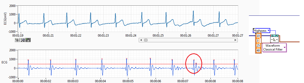
I have RCV of the ECG signal. I filtered the ECG signal and get the resource (interval between each pulse of ECG) records.
The source of the signal have noise I use a threshold but sometimes spikes of failure. Like the previous capture. Normally, if you get a pic of fault detected, I'll try to find this index to add to the left or right of the peak, normally I add to the lower value. This works if it has only a bad impulse between 2 good.
The problem come when I have more than a ridge between the two coupons.
Also, when the impulse of R a loss threshold I have trying to find the index and get 2 new reading making division 2 peak value.
I have attached the method I've used to adapt it. I only works if I have 1 Ridge added on real measures of R or pulse 1 loss R, when I have several pics no work.
I would like to hear an idea to make it work better. I don't like the idea of removing the value interval, I have 2 hours of reading and if I remove the values I have lower data outoput is why I tried to summarize or division of values to get the correct reading without losing any data.
Perhaps, there is any better filter for ECG of entry, so I have a R-own pulse and less noise between ECG pulses.
Any advice is welcome.
Best regards, Fred.
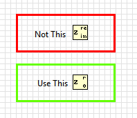
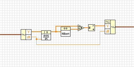
Almost. in the last step, you have extracted the real part of the complex waveform. Instead, you must retrieve the extent.
BTW, this idea isn't mine. I got from this article
http://www.ScienceDirect.com/science/article/PII/S0010482501000099
-
filter init/cont for an option several signals
Hello
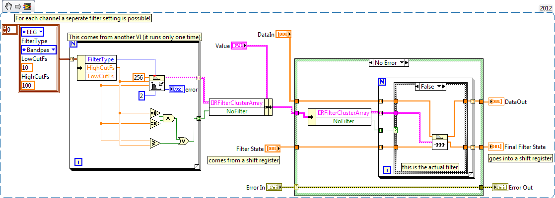
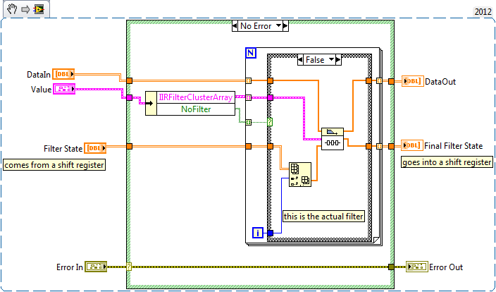
I have a table 2D with signals from a device of data acquisition, now I want to do a high-pass and low-pass filter for all signals, and each signal can have it's own high and low pass filter settings, and I can have any number of signals. When I connect my 2D array in a loop and place a filter inside with the init/cont option to true, it resets every loop pass. When I extracted a single signal and pass through the filter it works fine. But this isn't what I want, I want to have signals more filtered in different ways. I think I understand why he restarts, in the help file for the filter it is said: If set to TRUE, init/cont LabVIEW Initializes internal States for the final States of the previous call to this instance of this VI. So that means that each RollBar to pass, there are different data but the same instance... I wish I had different instances for each (for loop) switch. Records snippets of code and its results:
Any ideas?
Best regards
Thijs
Hello
I already solved!
See VI
The FilterState must be initialized, or else the forloop does not work...:
-
How can I filter the noise of a signal?
Hello
I wonder if someone can point me in the right direction.
I got the task to analyse the signal from a load cell, measuring vertical efforts on a buoy in the ocean waves. All I have are data files - Earth "calibration" run and a period of measurement of forces in the water. They are both simply traces time force vs. time. Calibration run consisted of hanging weight of the load cell. The problem is that the signal is very noisy, with a +/-10% fluctuation around the average. I don't see any particular model or the periodicity for the noise, but there may be something there.
As a mechanical engineer, I don't know a lot about the signal processing, but I think there may be techniques to characterize the noise and filter it essentially leave the signal of interest (buoy in the water). I tried to run Fast Fourier Transforms of the calibration and signals live (in MS Excel), but they gave me a huge spread of frequency component, some with puzzlingy large amplitudes. Can anyone suggest alternative approaches or indicate where I have gone wrong?
Thank you.
What are the software tools you have at your disposal to achieve this? Using LabVIEW? What is the sampling frequency of your signal?
The first thing to look for are the functions of filter and start by using a simple low pass filter (for example: Butterworth filter). In view of your signal, you expect the signal to be less than 1 Hz, so put 1 Hz as the crossover frequency. Who should get rid of a lot of noise already.
-
DAQmx split or filter the signal
Goodday,
A map of 4461 PC, there are 2 mic's connected. I use the Read.Vi of the DAQmx for it with 'ai0:1' as physical addresses.
These signals is used to calculate the rms value.
And this value is sent to
Ai0-Ao0 online
and
AI1-online Ao1
But sometimes I want to use only one microphone and so only for example use "ai1" However when I do this the Ai1 signal is at Ao0.
AI1-Ao0 online.
It seems that the Read.vi write all channels "signals channel 0" instead of "Ai1 to waveform channel 1".
How can it be changed or filtered?
And is there a way to create a drop down menu to select Ai0:1 (multi-channel) control? one is to create is now only for selection of a channel.
The command select channel a constant has a menu drop-down to select one or more channels. Just use the browse option.
If you have only one selected channel, you don't have that one in the waveform table, so if you still want to affix a specific chart, ai1 put function index in array inside a case statement. You have three different only case - ai0 ai1 only, ai0 and ai1. Wire instruction box for graphics.
-
Error 20020 - when you try to filter the raw signal of PPG
I have a few points of raw data from PPG, I want to divide them into AC and DC components, my supervisor told me to use a filter band pass with the upper and lower cut-off frequencies like 0.7 to 1.1 Hz respectively, I know why I get the error as my high frequency is higher than the sampling frequency, but is there a workaround?
I have attached my VI and the raw data, there is no header information and the left column is the time in ms, the right of the value of the intensity.
Thanks in advance for any help
Hi Seancassidy
I've attached a screenshot of how you can solve your problem.
I have included a constant of 0.001 to give you the resolution of 1 ms.
You can find more information about this issue in the link below:
http://digital.NI.com/public.nsf/allkb/ABBD3A7BC25E17C8862561270058A4A0?OpenDocument -
Satellite L450 - 13G - No WLAN signal after a few minutes
Hello. I just bought a L450 13 G with Windows 7 pre loaded.
I noticed that a lot of times drops wifi connection. It starts as an excellent signal and then suddenly fades to no signal after a few minutes. I can't get it remains connected, if I'm in the same room or the next day. I have also a few years L or U 200 (I think) and it remains connected wherever I am at home.
What could be the problem?
Hey Buddy,
I assume you are using the preinstalled version of Windows 7. Is this good?
If so try to update the WLAN driver. If you are looking for your laptop model, you will find the latest version on the Toshiba site.In addition, check the configuration of the router. If you use a MAC address filter, try to disable it. Try another encryption and password encryption.
Also check the firmware if you use the most recent one. -
I have a MacBook Air. I use OS x El Capitan V10.11.12. 3 days ago, I installed a printer Epson L355. Everything seemed fine, when I first printed a few pages. I installed the driver delivered with printer and followed the Mac set up. The process has not completely finished the whole upward. I then found a Mac driver Mac page and installed (I think - how will I know?) and it seemed ok. When I used it the next day I kept getting message "filter failed" when you try to print from wifi. There is a strong wifi signal and scanning is ok. I can sometimes print a page of safari, but not from Word. I tried to delete and add printer's done everything to nothing. get him looking for a printer then message "filter has failed", with the printer in the "inactive"
Can someone help me please? I'm getting worried and frustrated in equal measure. I'm not a techie and really evil.
The message failed filter keeps the driver having problems of compatibility with the operating system and not the network connection to the printer. You mentioned with the driver supplied with your printer. This is linked from a previous version of Mac OS X, because sellers do not tend to get the latest drivers on the CD supplied with the printer. And then you install another driver, you can have caused even more conflict. So I would recommend that you delete the printer Printers & Scanners and then using the Finder, select go > go to folder, and then type/Library/Printers/Epson and press the Go button. This will take you to the Epson folder that has all the files in the printer driver. Select all the files and then trash them. Then, restart your Mac and when you are logged in, go to the Epson website and find the L355 printer driver that supports OS X 10.11. Download and install this driver, and then add the printer via Printers & Scanners again. Then see if you can print.
-
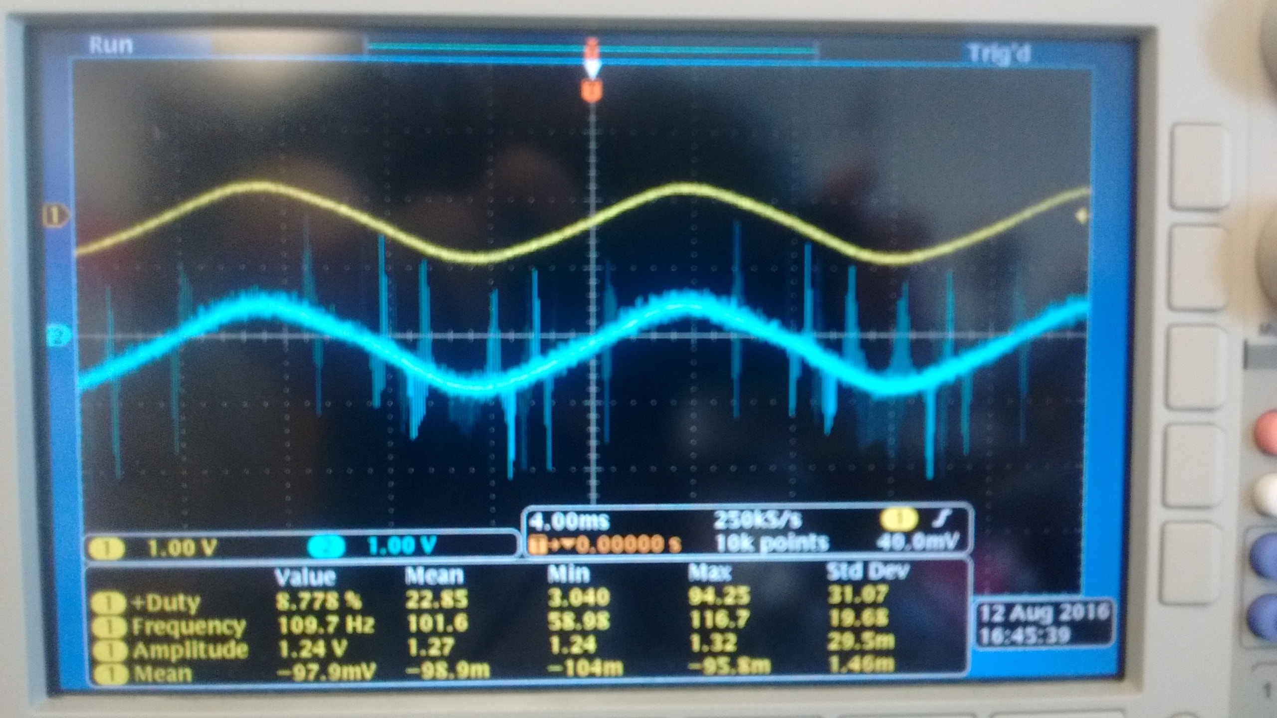
I currently use a NI 9215 module with BNC terminals to read the outputs of two different types of voltage sensors. Probe is a probe differential o-scope (Tektronix P5200A) which has a rejection of sound very good, while sensor B is a shunt isolated hall effect measurement using a LEM lv20-P and a custom PCB, which has a considerably lower noise rejection. Noise in the circuit to be measured is mainly the result of a H-bridge Inverter circuit that goes to 10 kHz. A picture of two sensors measuring the same signal displayed an o-scope is shown below with the sensor signal on top and B sensor on the bottom.
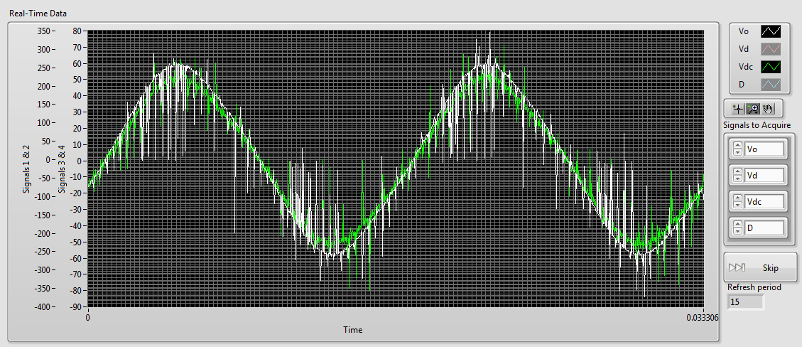
As you can see there is a lot of noise in the B sensor while sensor A is most often silent. When I connect then both of these signals to my NI 9215 I get the signals shown below (75 kHz sampling rate), sensor A appears in white and green B sensor (ignore the differences in scale, it's programmatically).
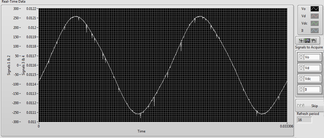
As you can see the noise level in the two now is comparably high. However if disconnect us the 9215 B, the signal from the probe sensor then replaces the image below:Although there are some present noise, the signal is much cleaner than before. The natural conclusion that I draw from this is that there is significant interference between the two signals. The same wiring is used for connecting to the 9215 as o-scope, and the two sensors use shielded twisted pair cables. This amount of crosstalk seems very high compared to the - 80dB listed in the specifications of the 9215. Any ideas what could be the cause, or how to fix it? Unfortunately, I am currently unable to afford a second sensor A.
1. by the impulses of the runt, I was meaning extremely short pulses on A sensor. If they are short enough, you will not see them unless you are looking for.
2. my concern is whether the switching noise is contaminant entering your power supply through the electric wiring. Of course, good feeds should filter this point, but it's just another thing to check.
3. the quick and dirty way would be to use a BNC T-connector to connect the oscilloscope and the ground in this way.
Suggestion of ferrite chokes on instrumentation Henrik is a good.
I understand that this type of inverter using the load (normally three-phase current motor alternative) to filter the frequency of bridge (10 kHz in your case) to the required frequency (normally 50 - 60 Hz). This means that high frequency currents go all the way to the motor, if they are not filtered by the cables first. You can not just screen the housing of the inverter, because the currents of high frequency down to load part of its operation. If you start testing things, you will all the way from the inverter to the load of the screen and will be impossible to Rodez to meet your instrumentation.
Standard WARNING: If you are tempted to connect directly to the UPS output and reduce until the input voltage range 9215: first of all, make sure that a qualified person has verified your wiring. Second place of fuses in all lines near where the tension is taken offshore. A UPS maybe a current loophole in the beach A 100 and you don't want that to the bottom of your wiring of instrumentation. Not directly relevant to your ad, but I feel that I specify.
-
How to filter the traces of tension TDMS after acquisition?
Simple question. We have acquired a lot of electrophysiological data with express signal. We now need to filter data after the acquisition for later analysis. I can import the files TDMS tension of previous experiences, but can't seem to run the filters we used on the side of the acquisition to filter the existing traces. Is there a simple way to do this?
-smb
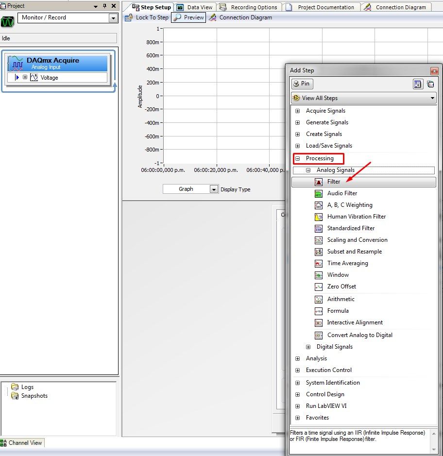
Hello Chinchilla,
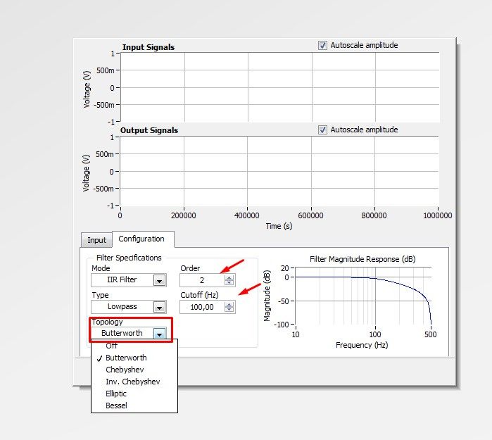
I enclose a few screenshots on how to add a step to an analog input filtering. You can select the type of filter and order too.
In this screenshot you can check how to change the configuration of the filter
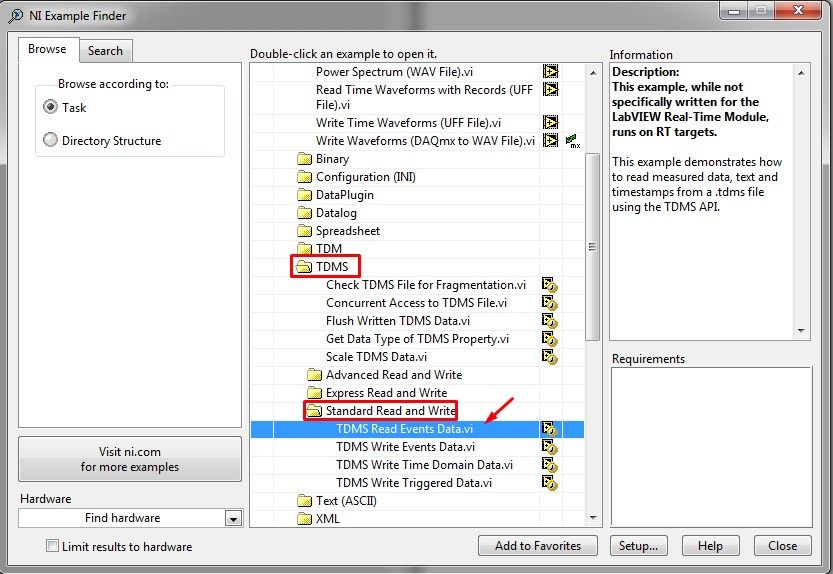
Finally, you can access the TDMS of LabVIEW file with one of the examples of PDM. Please follow these instructions:
1. open LabVIEW
2 - go to help > find examples to open the Finder 'example '.
3 - Go to Fundamentals > file Input and Output > TDMS > Standard Read and Write and select the VI named TDMS read Events.vi
You will need to know the data present in the file to read correctly. For this, you can use the leading PDM Viewer VI:
http://zone.NI.com/reference/en-XX/help/371361K-01/Glang/tdms_file_viewer/
Or you can use the Toolbox for excel: http://www.ni.com/example/27944/en/ (allows you to transfer the data to Microsoft Excel).
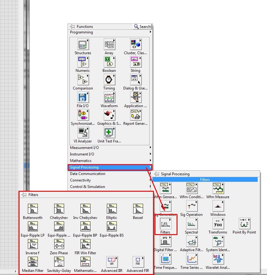
4. After reviewing the data, you will need to apply a filter. You can find the filter functions in the range of Signal Processing.
Please let me know if you have any questions on this subject.
Kind regards
Maybe you are looking for
-
Impossible to open a URL in a new tab using a submenu of bookmarks
I have just been upgraded to v 35.0. Before the upgrade, I could navigate my bookmarks menu in a submenu and place the cursor on a URL. Right click raised a menu popup allowed me to open, open in a new tab, open in a new window, etc. After the update
-
What video formats Journe Air 1000 is supported
1. what video formats can be played on it?2. is it necessary to convert the video using SW closed or not Thank you
-
Reproduction through loudspeakers for computer, no helmet, when during an audio Skype call
Hi all I've seen a few of these topics that are similar, but none that I have met have my setup. Let me describe quickly. I have my laptop speakers, a usb headset that I use for Skype and that I don't have permanent plugged into the laptop using a mi
-
graph of a few blocks after a specific location
Hi I'm new to view lab and boasts a location on a chart to a number on the xaxis in the waveform graph. I want graphic 2 blocks of data after my desired location how can i go by doing this. the location of the original is in time... but not in real t
-
Family Safety Windows blocking is not enough
I have activated Windows parental controls for a child account on Windows 8.1 and disabled all applications that are registered except Chrome. I tested and it blocks a lot of things, but allows much more than just Chrome. I disabled the downloads in