Simulation freezes Multisim
Hi all
I played a bit with multisim for a few years now, but later began to really use the features of simulation of the program. I noticed that transient analysis of the very basic circuits seem to work fine, but nothing more than (especially those using pwm controls) after bogged down as some ridiculously short period of time. Also, before it freezes, things as the output of the oscilloscope function very slowly. I have attached my circuit for reference and using all that you wonderful people out there. What I am doing wrong?
The wizard of error correction is not really take care of the problem.
FYI, this is a converter circuit high power for which I would like to study the out performance characteristics by changing the frequency of the triangular wave or setting of the amplitude of the sine wave from 0 to 1. The goal is to produce a sinusoidal current output to the primary of the transformer. The resistance of inductance and conductor of leakage have been modelled, as well as an inductive load on the secondary of the transformer.
Thank you!
Yes, I tried for a few days and all the other typical timestep of bugs and it does not always work. The solution was to replace the igbt with the command switches in idealized voltage and barrier diodes schottky antiparallel... and on the ground of the transformer floating seconday. It works now
Tags: NI Software
Similar Questions
-
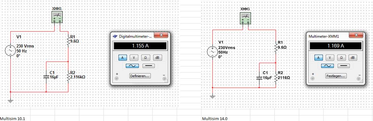
difference of simulation between multisim 10.1 and 14.0
I've been using Multisim 10.1 for check and create examples for students and want to spend 14 Multisim. Simulating a small ac-circuit I got different using multisim 10.1 and 14 results.
The result of multisim 10.1 is identical with the manual solution.
No idea, what could be the problem?
concerning
blanne
Hi Blanne:
The default setting of simulation in Multisim is letting his engine to automatically determine the TMAX, the maximum allowed timestep. In version 13, we have modified this code in such a way that it will leave the slower to simulate faster real-time frequency circuits, we did this in order to accelerate simulations as requested by users. Most of the time, this change has worked as expected, but your circuit is a clear example of a negative effect of this change. Its accuracy is affected by larger time.
In your evaluation of Multisim 14, you can quickly change that. Click on the Interactive analysis button in the toolbar to open the properties of the analysis and in the analysis of Simulation Interactive > look tab crawl settings for the checkbox control labeled step of maximum (TMAX), place a check and let it set to 1e-005. Make your simulation again and you will now see the 1.155 a result in the multimeter.
(Version 14 has been automatically calculate the TMAX as 1.25e - 003)
I'll file a defect report so we review how automatically determine us TMAX so he will not state as in this example. I hope my explanation helps you advance your evaluation of the software.
Kind regards
-
A simulation of Multisim 12 in labview11 display
Hi admin, I simulate a circuit with Multisim, it works well, I mysignal, I aqueillir this signal, labview, I still install the resource kit, I plugged the connector, I have no evidence for labview multisim12 in2011, how?
Hello
I don't know what your problem is. Please take a look in the link below. It shows you what you need to be able to use co-simulation.
http://zone.NI.com/DevZone/CDA/tut/p/ID/13663
I hope this helps.
-
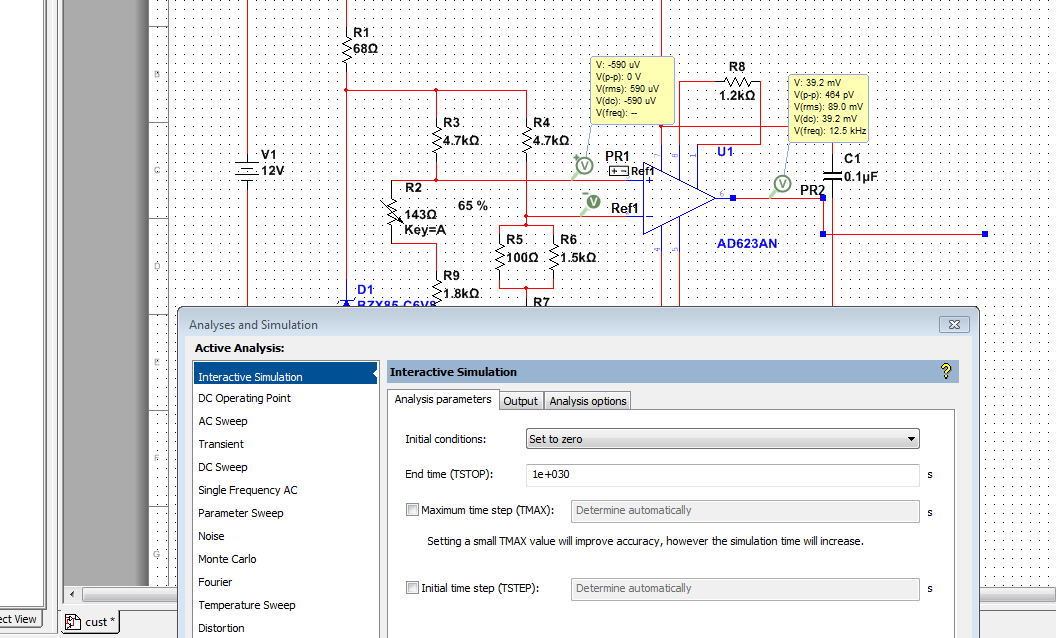
What is the problem in simulation in multisim
I want to know that when I try to simulate it gives me error can someone please tell me what is the problem?
Kind regards
Saami
Try to set your initial conditions more zero on the changes described above:
It seems that this circuit is particularly sensitive to the problems of convergence.
Also, if you use the 14.0, new measurement probes can be an interesting alternative to the instruments and can help when running in questions of convergence.
Let me know if this is useful,
The f
-
Library of Multisim of AD5700 Modem HART for the simulation file
Hello
Can anyone give any assistance with simulation on Multisim with PIC 16F877A with HART communication on industry standard 4. 20 Ma loops...
I'm trying to simulate Modem HART AD5700 on Multisim with PIC16F877A. I want to send serial data to AD5700 using UART interface and then see the corresponding analog output signal varying in frequency (based on the binary data that is sent to AD5700) on HART_Output. Unfortunately, after a search too, I could not find Multisim for IC AD5700 library file.
Can someone tell me how to simulate AD5700 on Multisim? or any other to get out of this problem?
Thanks in advance and waiting for your kind response,
Hello UEC.1000,
I don't know what version of Multisim you have, but I tried to check on the different versions and was able to confirm that the model you need is not in the Master database. You can see this link:
- Models and elements of NI Multisim
http://www.NI.com/white-paper/5607/en/
Because it seems to be that the component is not present in the database, I want to show you the following link that could give you workarounds.
- Where can I find new components or libraries of Multisim?
http://digital.NI.com/public.nsf/allkb/260504431AC975E886257C7C0063CB27
Thank you very much for your question, I really hope this information help you.
Kind regards
Luis.
-
Multisim: Spice LT1568 modell, simulations of AC
Hello
I'm building an at the ADC input stage and do some prior to sampling of conditioning of signals. I am using LT1568 filter, but when do simulations in Multisim 13.0 I don't get the results I expect low-pass.
I have provided my scheme, that is configured as a filter of LP 4 pole with frequency 5 MHz. What simulation it act of as a filter HP for some reason any...
I tried LTSpice and everything works fine and I contacted LT (Linear Technology) to get help but they suggested me to stick with LTSpice, which is not ideal for me.
I tried to make my own template code/description spice, I found on the internet but without success. Perhaps because of knowledge limited spices.
Attached is the schema
Thanks in advance
Sebastian
Try this.
-
Compatibility of Simulator - Win7 x 64?
Hello
I use the 8330 Simulator, specifically:
BlackBerry_Simulators_4.5.0.127_8330
and the Desktop Manager:
Desktop Manager 501_b049_multilanguage
The Simulator freezes frequently, and many times the application does not close without killing the process through the Windows Task Manager.
Is anyone out there using these apps on Windows 7 x 64?
Thank you.
Bill
Hi Bill,
Please note that the current development tools, including simulators, are not guaranteed to be compatible with 64-bit operating systems. Asking to close the simulators since the Task Manager is currently a known side effect to run in this environment.
Kind regards
-
Can not read files in Simulator
I used a folder on my pc to the SD card file system.
I used the following code to read the file that I copied to the shared folder. But the app could not find the file. In debug mode, it appears an error code 1003.
Try
{
FileConnection fconn = (FileConnection) Connector.open ("file:///Media Card/my.xml");
If (! fconn.exists ())
{
System.out.println ("the file do not exist!");
}
}
catch (IOException e) {}
System.out.println (e.getMessage ());
}I also tried to use the FilePickerDemo which is an example of a project. The FilePickerDemo can navigate in the file but can not find the file my.xml either.
Does anyone know where I could be wrong? I worked on this question since yesterday afternoon. Thank you very much!
BTW, I use 8900 Simulator, Windows 7 Pro 32 bit Eclipse with the plug-in.
The Simulator freezes after a while, it looks like a memory leak. Also, if I use the simulator of 9550's, it could be worse. The simulator of 8350's is the only does not freeze at any time. Anyone happens to know on this issue?
Problem solved. The directory must be file:///SDCard/xxxxxx
I misunderstood to file:///Media card/xxxxxxxx, since when I've explore it media, is what shows on the screen.
-
output signals of the rectangle a PEAK sine wave conversion
Hello
I have a question on the treatment of a PIC16F84 output signals. It seems that the simulation of Multisim does not work properly - but before I blame Multisim, I ask the community NOR or software engineers or a solution. Because I'm German, you are invited to continue this thread in German if it is allowed by the rules of the forum. If you need additional information to analyze my problem, I'll be happy to provide.
The circuit itself has to convert "composition by pulse" signals "tone" (DTMF tones). So you can get old, classic phones work on new devices that do not support the "composition of pulse" more.
The circuit is powered by the analog telephone line current loop line. The PIC is provided by a rudimentary voltage regulation and count pulse signals (voltage failures / power interruption on the telephone line). After that the captain means the series of impulses in their equal number (e.g. 3 pulses = number 3). The captain gives finally two signals with different frequencies to generate a DTMF tone (e.g. number 3 here is 697 and 1477Hz). As you can see in my PDF file attached, it works very well.
Now I have to convert the rectangle wave given by the captain to an at least similar to a sine wave form - otherwise the device that receives the DTMF tones won't understand them.
So I connected a low-pass filter at the output of the PIC. Now, expect the rectangle signal to be smooth in a way as the 'e-function' will (loading / discharging a capacitor through a resistor). But the results are very far from that - as you can see I have very strange curves.
When I implemented a frequency generator with the same output signal as the PEAK and the low pass filter even I get curves as expected.
So we can say that the output of the PIC works like a frequency generator in my circuit. But why does the filter not behave as it should?
I've tried a lot of different values for the parameters of my RC-filter and simulation - this does not solve the problem.
It would be nice if someone has any idea how to solve this problem.
Thank you.
The output impedance of the PEAK may be too high. May be that my car 50 output? Try scaling of impedance of the filter. Do the 10000 ohms resistance and capacitor 10 nF.
Lynn
-
I'm using LabVIEW-Multisim co-simulation for ordering a buck converter circuit. When I run the VI which controls the converter circuit in Multisim, I get an error code-2367. Specifically, its this error:
External model buckconv.vi/Control & Simulation loop
doAnalyses: Timestep too small(M202)
I think that the error is the framework of simulation in Multisim, but I do not know what parameters to change so that I can solve the problem.
Hello
Normally for a problem of scaling of the timestep I would adjust the tolerance values. In your loop control of Simulation, if you pull the bar to the left, there are 2 options for tolerance (relative and absolute). Try decreasing the accuracy of these (instead of e-12, e-08 of use). Also the minimum and maximum values of stepsize control are there as well if you can try chaning those. Let me know if it works.
Best regards
-
Problem opening the app in the blackberry playbook
I created .bar file and deployed Simulator playbook. When I open the application Simulator playbook it shows a screen of loading with white background and after a while, the screen turns off and Simulator freezes tried uninstall and reset the time Simulator couple but no luck. If anyone has faced the same problem and solved. ??? Please answer if someone has the solution.
Can you post what version of WebWorks SDK built you the bar of the file with?
Applications built with beta WebWorks 2 won't work on the 0.9.4 Simulator. They are incompatible binary. You must re - package your application using Beta 3
-
How to restart PlayBook OS VM?
So far I've been hanging my sessions when I left VMWare... I'm on a mac...
But now the simulator which was released yesterday has hang when running my application...
It seems in VMWare my only options are to suspend and resume... Restart VMWare itself, just bring back the BONES of the PlayBook in suspended state it is for me...
Is there a way to restart the operating system? Surely, there must be a way... Or to delete the operating system and reinstall?
Hey,.
I'm using a mac and vmware fusion. There is an option to restart the simulator by itself and not the whole of the VMware program. When you are in VMware and the Simulator has frozen, go to the virtual computer > restart. This will restart in turn just the Simulator, and it will be in his pre-develomental mode screen.
also of note, if you do not have a persistence of data and that you have permission to start, I recommend taking a snapshot and restoration of this snapshot as soon as the Simulator freezes. its much faster to return. Here is a thread with more details:
hope that helps. Good luck!
-
Background switch detected for MyApp (24) who doesn't have the tunnels open - defocus is NOT called
I get the error "background switch detected for MyApp (24) who doesn't have the tunnels open - defocus is NOT called. Then the Simulator freezes and I can't do anything. Tried to debug but no luck!
My application has two other entry points implemented from article http://www.blackberry.com/knowledgecenterpublic/livelink.exe/fetch/2000/348583/800738/800901/How_To _...
Please see code below
public class UserInterface extends UiApplication{

    public static void main(String[] args){

        if ((args != null) && (args.length > 0) && (0==StringUtilities.compareToIgnoreCase(args[0].toString(), "GUI"))){

            UserInterface theApp = new UserInterface();
            theApp.enterEventDispatcher();
        }
        else {
            try
            {
                Wait();
                            SetTimer();
                ManageResources mg = new ManageResources();
                System.exit(0);

            }
            catch (Exception ex)
            {
                if (RuntimeConfig.DEBUG)
                {
                    System.out.println("UserInterface, main:  " + ex);
                }
            }
        }
    }
    public UserInterface() {
        //  DialogDisplay dd = new DialogDisplay();
        pushScreen(new UserInterfaceScreen(this));
    }
I also had this problem, the cause is that my computer is behind a proxy firewall so that MDS services Simulator cannot connect to internet, I added the following lines in the file rimpublic.property in the directory "Eclipse\plugins\net.rim.eide.componentpack4.7.0_4.7.0.46\components\MDS\config".
application.handler.http.proxyEnabled = true
application.handler.http.proxyHost = proxyserver
application.handler.http.proxyPort = 8080These lines must be placed in the [MANAGER HTTP] section.
It will be useful.
-
Multimeter simulation Multisim not showing after reading press simulation
I'm running student multisim version 14. I made a very simple circuit and to place two multimeter and run a scan dc.
But the problem I am experiencing that I'm window calculation but multimeters not show any value of simulation.
can someone help me understand this please.
Hi shabeesatsangi,
The meter components are intended to be used during the interactive simulation. When you run the DC OI analysis, you will see the results in a table in the grapher.
To display the values in your multimeters, change your simulation mode to Interactive and run the simulation.
I hope this helps,
Jeff
National Instruments
-
Multisim co-simulation / LabVIEW
Is it possible to add contacts from two States to Multisim and control of Boolean way to LabVIEW?
the attached example schema
Maybe you are looking for
-
I don't want to zoom in on each page. There is no way to 'set it and forget it '?
On Flickr, I have to zoom because, for some reason, the page has decreased with the new Firefox. I think the zoom corrections of things twice, only, I have to zoom twice each page! No there is no way to change a parameter instead of zoom page-by-page
-
Satellite M40X - keyboard unresponsive
HelloMy laptop keyboard is not responding. I can not connect, if I set the restore disc and press on 'C' by following the instructions it happens with the Bios setup and I can't navigate through the options with the arrow keys. On the login at startu
-
WARNING: Incompatible Arg. You can't use stack Variables If generating series is not defined
What does this message mean? "WARNING: incompatible Arg. you can't use stack Variables If generating series is undefined." Where can I put generate series only? Thank you Derek
-
Pavilion E018TX: I forgot my BIOS password
Hello I forget my BIOS password. Previously, BIOS Locked by asking the password and at that time, I used the default password as 47141111 and I entered the BIOS. I changed the Pwd right there and I forgot now. I also tried with BIOS default Pwd 47141
-
My printer is suddenly without a driver. How is this happen and how can I solve this problem?