Size of USB data acquisition 2008/USB 2009
We have several USB 2008 Renault in my company, and we plan to go to a USB 2009. We use them in some regions of space is counted rather however, and I was wondering if there is a difference in the physical size of 2009 compared to the 2008 USB USB.
Thank you
There is no distinction between 2008 and 2009. Could you be confusing a with a 6 2 and talk about the 6008 and 6009? If so, the dimensions are in the User Guide , which is something that comes with the units.
Tags: NI Hardware
Similar Questions
-
USB multi channel data acquisition
I use the VI to arduino HC-06 bluettoth of data acquisition. I would like to acquire data multicahnnel
Could you suggest me how to acquire multichannel data from USB? To do this, how I have to program the arduino?
The crux of your property doesn't do anything since you not write anything.
Why you set the number of bytes to read at 8? You send more than that. You should be able to set it to a high number, such as 1000. Why do you use a dbl for this control?
-
6361 versatile usb data acquisition does not automatically detect the SCXI chassis/accessories
versatile usb data acquisition 6361 will detect automatically SCXI chassis and accessories?
Hello kdCMC,
As far as I know that the SCXI-1600 USB Module is able to auto-detect SCXI Modules.
This is also mentioned on page 11 and 12 of the following SCXI to start document:
http://www.NI.com/PDF/manuals/373236m.PDFAll data (including USB-variants such as the NI USB-6361) have only a 68 pin shielded cable (IO) between the DAQ hardware and the SCXI chassis.
This cable does not auto-detect opportunities since it basically just "transfers analog and digital signals" between SCXI chassis and DAQ hardware.Is there a specific document that created the confusion on this subject?
-
USB 6008 data acquisition: automatically turning in a port
Hi all someone could please help me.
I need to autoamtically send output didgital since my data acquisition based on a value. the bottom of my little project. I read in a database if a value is equal to a certain value, I want to send a digital camera of the signal of acquiring data in a relay, so for example if the value 1 database generates a digital signl 0 7 port line.
If someone could help it would be much appreciated
So what's the problem with sending AUTOMATICALLY one. You simply compare the value of the database. A comparison function returns a true or false, which is quite ideal to display a true/false signal.
Fix the code you wrote. This is not a service of howework and see some code real goes a long way to get detailed help.
-
USB-2009, Task.Timing.ConfigureSampleClock fails
I work with a USB-2009 and want to write a byte array to the digital output using DigitalSingleChannelWriter.WriteMultiSamplePort. The following c# code illustrates what I'm trying to do. An error occurs when ' task. Timing.ConfigureSampleClock' is performed and the message below.
I read the documentation of NOR-DAQmx .NET. It does not specify what are the classes and/or function should not be called on the USB-2009 so I don't know whether or not the "ConfigureSampleClock" can even be used in this situation.
Can someone tell me or provide me with sample code that shows how a byte array can be sent to the digital output on the USB-2009? If the USB-2009 is not designed for that, then that would also be helpful to know. If your example is only for analog output, then I think it would be just as good. I am able to output a successful single byte, one at a time, on the line of digital output... but not a byte array.
Thank you
Ian
===============================
Code example
Note the following object instances:
"Simulator" simulates a wave with an amplitude of 255 square
"deviceID" manages the the string ID of the USB-2009
int x = - 1;
Byte [] waveData = new Byte [Simulator. Count];
{foreach (Double sample in the Simulator)
waveData [++ x] = Convert.ToByte (sample);
}using (task task = new task ("myTask")) {}
task. () DOChannels.CreateChannel
deviceID + "/ port0."
"myPort."
ChannelLineGrouping.OneChannelForAllLines
);task. Timing.SampleTimingType = SampleTimingType.OnDemand;
task. () Timing.ConfigureSampleClock
String.Empty,
samplingRate,
SampleClockActiveEdge.Rising,
SampleQuantityMode.FiniteSamples,
Simulator. County
);
task. Control (TaskAction.Verify);DigitalSingleChannelWriter writer = new DigitalSingleChannelWriter (task. Stream);
writer. WriteMultiSamplePort (waveData, true);} / / using (task task = new Task()) {}
===============================
Error message generated by executing the line "task. Timing.ConfigureSampleClock':
NationalInstruments.DAQmx.DaqException: The requested value is not supported for this property value.
Property: NationalInstruments.DAQmx.Timing.SampleTimingType
You asked: NationalInstruments.DAQmx.SampleTimingType.SampleClock
You can select: NationalInstruments.DAQmx.SampleTimingType.OnDemandTask name: myTask
State code:-200077
to nNIMSSAIL100.StatusObserverT<><>
 otNetApi > >. CheckWithName (StatusObserverT<><>otNetApi > *, tCaseInsensitiveBasicString
\,_STL::allocator \,nNIDMXS100::tLocaleConsideringWideStringComparitor\,nNIDMXS100::tLocaleConsideringWideStringCaseForcer>* pName) at NationalInstruments.DAQmx.Timing.set_SampleTimingType (SampleTimingType value)
at NationalInstruments.DAQmx.Timing.ConfigureSampleClock (String signalSource, Double rate, SampleClockActiveEdge activeEdge, SampleQuantityMode sampleMode, Int32 samplesPerChannel)
at Test.MainForm.testNINetLibrary_Click (Object sender, EventArgs e) in C:\Users\XXXXXl\Documents\Visual Studio\Projects\Digital IO - test\MainForm.cs:line 197
Hello Ian,
The error you see is because you try to cinfigure a sample clock that is not actually present. The USB-6009 case is completely timed software (which means that the values are updated based on your loop rates and the speed at which your computer can change). It seems that you are calling the right to property, the error message seems a bit misleading. We can consider the issue to see if it's something that needs to be corrected. Normally, the timed SW just requests do not configure a sample clock. Here's an exit code only once, so do not hesitate to repeat just update you need.
int main (void)
{
error int = 0;
TaskHandle taskHandle = 0;
data uInt32 = 0xffffffff;
char errBuff [2048] = {'\0'};
Int32 wrote;/*********************************************/
DAQmx Configure Code
/*********************************************/
DAQmxErrChk (DAQmxCreateTask("",&taskHandle));
DAQmxErrChk (DAQmxCreateDOChan (taskHandle, "port0/Dev1", "", DAQmx_Val_ChanForAllLines));/*********************************************/
Starting code DAQmx
/*********************************************/
DAQmxErrChk (DAQmxStartTask (taskHandle));/*********************************************/
DAQmx write code
/*********************************************/
DAQmxErrChk (DAQmxWriteDigitalU32(taskHandle,1,1,10.0,DAQmx_Val_GroupByChannel,&data,&written,));Error:
If (DAQmxFailed (error))
DAQmxGetExtendedErrorInfo (errBuff, 2048);
If (taskHandle! = 0) {}
/*********************************************/
Stop DAQmx code
/*********************************************/
DAQmxStopTask (taskHandle);
DAQmxClearTask (taskHandle);
}
If (DAQmxFailed (error))
printf ("error DAQmx: %s\n",errBuff); ")
printf ("end of the program, press the Enter key to quit\n");
GetChar ();
return 0;
} -
In data acquisition, I use a loop to query the data from the hardware, another loop to receive the data from query sent by queue loop.
Each time the size of the transferred data matrix is perhaps not the same, so the system can assign different table size and recycle frequently.
It cost memory leak. Or it will slow down the performance, given that the size of the array is not fixed, so everytime need to create a new array of size.
Any suggestion or the best method.
If I understand your description, your DAQ loop acquires data with the parameter of the function of reading-'1 ' for reading at the DAQmx samples. This translates into different picture sizes.
Passage of these tables directly to a queue is valid and she didn't mind important in performance (at least AFAIK) and it certainly does not leak memory.
So the question is more or less:
It is valid that the consumer receives sizes different picture for analysis? How your consumer manages these tables?
hope this helps,
Norbert
-
Data acquisition tool NOR-DAQmx with Matlab R2012a
Hello
I'm trying to control NI USB-6211 of Matlab 2012 using NOR-DAQmx Data Acquisition tool:
http://zone.NI.com/DevZone/CDA/tut/p/ID/3005
I'm working on win7 64 bit. And I see the device AND Measurement & Automation Explorer.
The tool does not work: DAQ_Demo_Browser do nothing. And I got the error "unexpected or unbalanced parenthesis or support" of AcqNUpdates_nonUI.m
What is the problem?
Thank you and best regards,
Arthur Shulkin
Hi Arthur,.
Tools OR DAQmx for Acquisition of data with the Software Inc. MATLAB® from The Mathworks, supports up to the 2008 version of the MATLAB® software. In order to use our products DAQ Multifunction with MATLAB® software, you could get back to 2008 or earlier, or instead use the Data Acquisition Toolbox provided by The Mathworks, Inc.
Another option would be to import your ".m" files in a node MathScript in LabVIEW and use the functions of NOR-DAQmx everything in the LabVIEW development environment. For more information on the Module LabVIEW MathScript, you can consult the information available on this link:
Inside of the LabVIEW MathScript RT Module
MATLAB® is a registered trademark of The MathWorks, Inc.
Katie
-
I just installed Win7 Pro x 86 on my Z600 workstation. It was an upgrade to Windows XP Pro. I'm missing the driver for PCI Data Acquisition and processing of the Signal and Hardlock USB 1.02 controller in Device Manager. Can someone help me find these drivers. I looked on the page of Support/Drivers for this model, but could not find anything.
Hello
You can get assistance on the HP Enterprise Business Forum since you have a professional worktsation.
-
LeCroy Waverunner 640Zi - Data Acquisition
Hello... I'm trying to set up my oscilloscope waverunner with LabVIEW SignalExpress for data acquisition.
I took the steps so far:
1 pulse generator hooked to scope of signal generation
2 USB scope to the installed computer with LabView
3 downloaded lecroyscope driver 3.2.9 - x 64
I turn on the scope and plug in the USB to the computer and SignalExpress begins.
a. start by using data acquisition
b. Add step/aquire signal / IVI aquire / IVI brought aquire
c. create new IVI session... resources descriptor (I choose my USB device ' USB0::0x05FF:0 x 1023: 2812N61507:INSTR '), I select the right driver (lcscope), and I do not click enable simulation data, press ok
d. I still receive configuration errorse. did the research... some forum said goto MAX, find drivers and uncheck the Cache and the exchange of check
f. attempt to initialize... always get config errors.
g. return to MAX... change to simulate with specific driver.
h. initialization works... NO errors, BUT no data are acquired.
Help, please!
Hello
Sorry to jump in if I was out of the country for a while and am still catching things in my office.
I think you are looking for someone to say yes, "you can connect to the scope with NOR-MAX and VISA, and here's how interactive tool do"
A few things:
LabVIEW for XStream extended driver is the right one. It works with all the TeledyneLeCroy Windows based scopes.
As I see has already been noted. (I'll give Kudos soon), the scope of application must be configured to use interface USBTMC. To do this, go to the drop down Utitlites on the scope menu and select "utilities configuration... '. "in the tabs that appear at the bottom of the screen, select the 'Remote' tab and make sure that the interface type is set to USBTMC. This will also show you the VISA resource (I see it in the title of the image of VISA interactive tool indicated in a previous post).
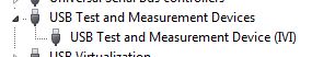
Once this field is selected, the PC should detect the USB connection and install the device. (you can see in your device manager as a Test of USB and the measurement device):
Once this is done, you can then enter the NOT-MAX and it will detect and display resources. You can now communicate with the device:
If you have problems, do not hesitate to give me a call and I'm happy to walk through it over the phone.
Kind regards
Leonard Brown
Technical sales engineer
Teledyne LeCroy
1-800-553-2769 -
Configuration of the two of the same model data acquisition
Hello, community of NOR.
I'm an intern in mechanical engineering with experience in base with LabVIEW.
I would like to speak to OR directly on this issue, but I don't have a service contract and my company wants me to understand this before you buy LabVIEW.
I hope that someone has experience about my question, and I would be very happy to help.
We intend on purchasing an expansion card for our acquisition of data (OMB-USB-2416), but unfortunately it is offline and no custom would not happen in time.
So, I need LabVIEW to read voltage HAVE two of the same model of data acquisition, which would amount to about 30 channels.
Is this possible with LabVIEW?
Thank you.
Measurement computing says that the "physical channels" dropdown list is automatically filled in once both devices are configured.
-
We send 5v data acquisition using a voltage generator. Hook us it up to a voltmeter and see 5V. When connect us the generator voltage to a valve "normally open" parker, the voltmeter indicates .14V. It seems that when we connect the two sons of the valve for the voltage generator, the son act as pattern. We want to control the voltage flowing to tap through Labview. We checked the wires to the valve and they work very well, because if we send a constant 5V since the acquisition of data and put ashore, she, the voltmeter indicates 5V. Someone knows why the son act as pattern and low blood to .14V?
nsatpute wrote:
Our data acquisition is NI USB-6259. The valve requires only a 5V max and our DAQ provides up to 5V. However, after connecting the valve to the acquisition of data, the grave tension to almost 0. We start from the principle that the son somehow act as the reason, but we are not sure if this is the case.
The question here is not how much voltage the valve wants, it's the current needs of the valve. The 6259 can put only 5mA via an analog output. Your very likely tap needs much more than that. If you need to add in an amplifier circuit that can supply more current to operate your faucet.
-
I am writing my first app Measurement Studio DAQ but the model NI DAQ component not available under PROJECT > add new item.
-Execution of Visual Studio 2008 with VB and Measurement Studio Professional 2009.
It seems that I do not have access to the DAQ Assistant of Measurement Studio.
Download
More ms-help://MS. VSCC.v90/MS. VSIPCC.v90 / NOR. MeasurementStudio.2008/DAQIntegration/XML/Create_NET_DAQ_Component.html
- Open the project in which you want to create a component of data acquisition. ... Ok
- "SELECT project ' add a new item to launch the add new item dialog box. ... Ok
- In the categories pane, select Visual Basic components if you use Visual Basic .NET. Select Visual c# project items , if you are using Visual c#. ... NO... "Visual Basic items" is not part of the list of categories
- In the Templates pane, select OR DAQ component... Not available in the models pane
Help, please!
-David
Hello Panorama,
After installing Measurement Studio, OR-DAQmx have you installed? If so, you should make sure that the Measurement Studio for VS2008 component is selected to be installed. You can select the custom Setup option to check this setting.
Kind regards
-
How to get to multiple data acquisition voltage signals
Hi guys,.
I have to run an event for children to play with different types of energy production, so we have a wind turbine, solar panel and a generator. I have all of them connected to the ports of entry of the C USB DAQ series, I can't seem to find a way to make data acquisition out all three voltages simultaneously, the DAQ assistant in labview won't do it, AFAIK. I need all the outputs of all so that the children can see the reknewables plus and then complete the lack to win with the "power station" generator, so I need them all running at the same time. I had a quick glance at similar problems, but I don't see how they are relatable to my case.
I have attached the vi below, thanks for your help.
Amy
DAQ Assistant allows multiple entries of tension. When the analog channel selection hold down the SHIFT key and then select as many channels available, you want.
-
the relay control data acquisition
I am creating a vi that controls (press and release) several relay using a USB 6501 data acquisition. This should be a task relativily easy but I get flumoxed by errors. I tried to use the examples, but I get an error telling me that I need to use the mode of generation 1 sample (on request). Help, please
Sure. The easiest way is to have a DAQmx writing followed by a function of delay, followed by another entry, followed by another period. Simply plug the error links in order to control the flow of data. However, the VI would be insensitive so you can use a state machine or function elapsed time so that the VI can be stopped without waiting for waiting for him at the end.
-
Hello guys,.
I have a general question regarding the units of packaging such as the USB-9263 analog output signal. If I can use it instead of data acquisition to provide an analog voltage output?
Thank you
ELA
Yes, the 9263 can provide 4 output channels analog voltage (+/-10 v range) with up to 1mA of current drive. Looks like: it refers to the short circuit of conditioning of signals and some protection against overvoltage. Link below is the User Guide:
http://www.NI.com/PDF/manuals/372406b.PDF
-AK2DM

Maybe you are looking for
-
This has only started happening since Thunderbird has been updated to version 38.2.0.It seems to happen after restarting the computer (W8.0) of the State of "sleep".It seems that some mails are downloaded, then the program crashes and is then complet
-
smooth scrolling does not work as expected
With "smooth scrolling" I expect that, when you press the ARROW KEYS, the whole page move 'gently' and quite slowly. But this doesn't seem to work.Instead, press one of these keys in fact the cursor rushing through managers line-wise, "walking around
-
Here I have a 2011 mac book pro with a built in trackpad the difficulties of moving files from one folder to another via click dragging on the pavement, but moving the file won't spend 90% of the time someone has a solution to this long live
-
Need new taken for my Satellite L450-136
Hello I have a broken DC Jack his on a cable that plugs into the M/B, the problem that I have, I rang "Topaz", spare parts partner Toshiba officials and told me although he s on a card that you can not buy it separately, you need to buy the whole of
-
How to remove 2,000 word documents accidentally copied on the desktop?
Hello. At work, I tried to copy approximately 2,000 documents word of a folder to another folder, but somehow accidentally posted copied to my desktop word documents. Now, he is incredibly crowded and very slow start. I tried to do 'Order A' to selec