SMU 1073 of entry grounded
Hello
I was wondering how the reasons for a SMU 1073 chassis hybrid slots are connected in the chassis. I use 3 cards PXI-6255, although I don't think it makes a difference. What I'm looking for, it's that they are bound together or not, or a similar indication. Thank you.
UPDATE: I was wrong. Please refer to the following KB:
http://digital.NI.com/public.nsf/allkb/02A451C0A88A3EAE8625702F0059C98E
Kind regards
Brandon v.
Technical sales engineer
National Instruments
Tags: NI Hardware
Similar Questions
-
Acquire more than 2047 samples with the PXI-4461 instaled in SMU-1073
Hi all, I would ask you for help with the buffer limit.
I intend to buy digitizer PXI-4461 and he instal in SMU-1073 chassis, namely control via MXI Express of Labview installed on a separate computer.
What I need:
-to acquire data of a single channel of AI, but at least a sequence of 20 kS by a acquire task, in some situations until 200kS by a task to acquire.
The question:
- I can gain more than 2047 samples in a single sequence, like 200kS, with the PXI-4461 installed in SMU-1073?
Internal buffer of the PXI-4461 is reserved to 2047 samples. So I'm not sure if Labview can download remotely via MXI Express the data in the buffer of the PXI-4461 via MXI Express fast enough without any affection of the sampling program.
-in the case, this PXI-4461 with SMU-1073 isn't the right combination, what chassis and a controller can do?
Thanks much for the reply
Jan
It will work for you.
The on-board buffer 2047-sample is used only as a backup if the flow of data to the PC host (via MXI Express in this case) is not fast enough... that it will be (explained below). DAQmx transfers data from the buffer of the device to the host PC as fast as he can and, in ideal conditions, should not save the buffer 2047 much at all.
Let's just say you get 110 MB/s (randomly from a MXI data sheet) flow on your MXI connection. The 4461 has 2 analog inputs, which will be at 24 bits, we just round 32-bit in case it transfers the data in this way.
4 bytes/sample (32 bit) x 200,000 s/s x 2 (channels) = 1.6 MB/s, which is well below the 110 MB/s, which will make the MXI link.
clear as mud?
Germano-
-
Can I use a 6343 OR USB as an entry grounded to trigger an injector?
Hello forum members
I'd like to be able to fire a solenoid valve high speed (low impedance about 1.6 ohm) with a peak and hold the pilot injector (from AEM). The output of the P & H driver is activated when the trigger on input is connected to the Earth. Can I use the 6343 to provide this ground trigger? I read somewhere in the manual that I might be able to use a PFI or DIO line as output a 0 at the wheel. Is that what I'm looking for?
Thanks in advance,
-Mike
Mike,
On the second page of the document, he says: trigger impedance: 220 ohms, shot at 12 V input impedance ("draw" 60 my).
IF YOU CONNECT THIS TO A LINE OF DIO, YOU MAY DAMAGE THE USB-6343!
What you want is a driver as the series of ULN200x of ICs. They can handle the 12 V and 60 my. Pour reversed are available as well as high logic of the DIO line will be on the ground in the entrance to the injector driver.
Lynn
-
Hello Philippe,
Take a look at the example below. Retrieves the Min and Max of table X and also correspondent has the value Y.
Best regards
Klas
-
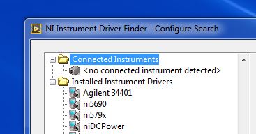
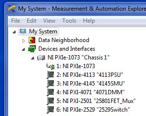
SMU Chassis or modules appearing does not in NI Instrument Driver Finder/connecte Intstruments
New user, to debut with a chassis SMU-1073, controlled by a PC, with supply POWER 4113, 4145 SMU and 4071 modules DMM.
I installed all the drivers from the supplied USB system and I can indeed see/control of the chassis and modules of NI MAX.
When I try to see the modules Labview 2012 or 2014 (I'm looking for example VI to start) Instrument Driver finder does not show any chassis or modules.
Looking for support OR but could find no generic "Here's how to start using this box OR $20,000 without flinching" first steps to help.
So, I was hoping that it was a mistake and plug and play like the other instruments I connected and used. What I am doing wrong?
Do not use the finder of the instrument. Use the help > examples of find and refer to material input and output. Be specific in listing of the drivers you have installed.
-
How can I measure the continuous component of the tension a SMU-4496 with LabView
Hello
I use an SMU-1073 NI with an SMU-4496 for several applications. In one of them, I would need the blood, maintain the continuous component (this is an accelemeter of MEMS). It's standing vertical, it gives, for example, + 2V and I need to keep reading this almost constant value.
However, with the DAQ Assistant in LabView, it seems that it only reads the component changing signal, as is it doesn´t to move, it reads almost 0. If it moves, the, the DAQ system takes the change but then returns to zero.
Is this normal? Read the constant part of the signal?
(I'm a mechanical engineer and I'm not at all an expert in acquisition of signals or data, so probably just something basic is missing me)
I have attached an example in which, after a change, it goes back to zero and the configuration in the DAQ assistant
Thank you
AC coupling is the culprit-it allows to block all components of steady state DC.
-AK2DM
-
Hi all
I have a 5732 NOR associate NI SMU 7962R, and they are integrated in a NI-SMU-1073 chassis. I wanted to test the data acquisition, so I plugged in a function to the AI0 generator. However, something strange happened. The acquired data seemed to be the derivative of the signal transmitted from the function generator: sine was still sinusoidal, but the square wave became pulse and square wave has become ramp! Has anyone seen what happens before? Thank you!
Best,
Tong
What was the frequency of the signals that you generated, and what are the options you have selected for the filtering and coupling AC/DC? If you have set for AC coupled entry or one of the active filters that resembles the behavior expected if the signal of interest is located in the strip of mitigation.
-
export to spreadsheet - data 2 channels appear in alternation with loop of producer/consumer
Hello
I'm having trouble with the function "Export the waveform to the worksheet" - but it is not clear to me if the problem is with how I use the export feature or if I am wrong concatenating two waveforms of different modules of the series prior to export, or if my queue is wired incorrectly for producer-consumer loops.
I use a hunts SMU-1073 with SMU-6361 and 4330 modules (tension and strain). I tried to change the example of the "entry analog cross synch" for use with a structure of producer-consumer (see VI below).
The output of the worksheet contains a large part of the data in the string tension, followed by a smaller piece of data (with timestamp) strain, after which the alternate output data between data of tension and strain.
Can anyone suggest where I could go wrong, or how I could solve this?
Attachments do not work, so I'll try to post in an empty message directly after this post.
Thank you
Claire.
That's what I thought.
A number of wire. -1 gives all the samples available in the buffer (which can be zero for some reason any). A number will expect that there are many examples. If the two readings can wait until they have both the amount of data requested. This way, they will also have the same number of samples and be better aligned in the text file.
Your loop will continue to run until you press stop or get an error.
-
FPGA/FPGA adapter creates 250 mV voltage offset
I use a high-7971R FPGA in a chassis SMU-1073 with the adaptation Module 5782 (DC coupling) and 2016,08 device drivers. When I turn on the chassis and my computer, nothing strange happens. When I try to run something on the FPGA, however, things get weird. Each piece of code works exactly as it should, but as soon as that 'open FPGA reference' finishes running the adapter begins to produce a voltage mV to 0 to + 250 Ai and AI 1. It doesn't go to AO 0 or 1 AO. This shift of power disappears temporarily as long as 'Reference FPGA open' or "Close FPGA reference" are running, but the only way to get rid of the tension of offset entirely is to restart the chassis. Can someone explain to me why this is happening and how to fix it? The FPGA code, I am running can handle a small shift, but this shift seems to be to saturate the signal.
To see the shift: branch I HAVE 0 and AI 1 directly in a 1 M complete oscilloscope.
It is planned. CDA on this FAM (and more high-end a/d converters) have a range of sampling which is not centered around zero. The front end of the compenstates of the FAM for this by applying an offset from the signal which would appear to the user that the range of the ADC is centered around zero. What is different between this FAMILY and other instruments, is that it is not an additional circuit preventing that this lag observed a user of height of the output of the analog input.
You see the shift happen to reference open FPGA is because that's when power to the GPA is activated. The shift should not have an effect on reading which provides the analog input. Just make sure you have impedance corresponding to the source of the signal at the analogue input and you should be good.
-
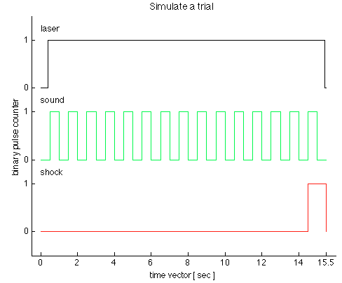
several finite pulse trains of TTL
Dear members of the forum OR,.
We have just received a chassis NI SMU-1073 with an SMU-6361 OR switched in PXI1Slot2 and a shielded connector BNC-2111. Aims to generate trains of three TTL pulses to control a laser, sound and shock via Matlab Application. I use the C OR-DAQmx API with Matlab MEX to integrate C in Matlab code.
I came up with the following code in the examples in C to generate a pulse over TTL time-based train:
initialDelay float64;
float64 lowTime;
float64 highTime;
uInt64 periodsPerTrain;
float64 taskMaxTime = (lowTime + highTime) * periodsPerTrain + 2 * initialDelay;Configure Pulse
DAQmxErrChk (DAQmxCreateTask ("", & taskHandle));
DAQmxErrChk (DAQmxCreateCOPulseChanTime (taskHandle, "PXI1Slot2/ctr0","", DAQmx_Val_Seconds, DAQmx_Val_Low, initialDelay, lowTime, highTime));Configure the Pulse Train
DAQmxErrChk (DAQmxCfgImplicitTiming (taskHandle, DAQmx_Val_FiniteSamps, periodsPerTrain));Departure Train
DAQmxErrChk (DAQmxStartTask (taskHandle));Wait for execution
DAQmxErrChk (DAQmxWaitUntilTaskDone (taskHandle, taskMaxTime));Clean
DAQmxStopTask (taskHandle);
DAQmxClearTask (taskHandle);I'm stuck with two problems:
1.) SMU-6361 has 4 meter signals ctr0-3. With the above code, I can generate separate tasks for each TTL signal and evoke them consecutively with DAQmxStartTask. But in this case, I guess that the tasks are not synchronized. Can I use the clock signal to synchronize the other 3, for the tasks of each is triggered at the same time? What will be the right way to do this with the C API? The step of the smallest of the discrete-time in the example is 500ms. see the picture as an attachment to check how the TTL signals should look like.
(2.) what is my physical connector on the BNC2111 to outsource these signals.
/ PXI1Slot2 / ctr0-> PFI12/P2.4
/ PXI1Slot2 / ctr1-> PFI13/P1.0
But what ctr2 and ctr3? How can I configure the physical connector outsource? Is there a function to specify that?
Thank you in advance for any advice, suggestions and directions!
see you soon,
go9kata
Hello go9kata,
for your second question, with the BNC-2111. You can route the signal from the counter for
lines PFI avialable on the block of connection BNC 2111 with the following syntax
DAQmxErrChk (DAQmxSetCOPulseTerm(taskHandle,"/Dev1/PFI0"));
I hope that helps, if not please let me know.
-
Pointing out that he / draining lithium with drums PXI Simulator?
I now tools of NEITHER: NI SMU-1073 and SMU-4154. Before I used it as a simulator of battery development councils of power with power supplied by SMU-4154.
However, now I would drain with a some models of drain to see the effect on his life of the lithium battery. I want to simulate the load of potential device that will power the battery.
How can I empty real battery (for example, the smartphone) using my battery Simulator? Is this possible?
Hi armendzh,
No, unfortunately, it isn't. To drain a battery, you need a load, not another battery. The SMU-4154 operates in 2 quadrants. It can only original, not sink. She can get a positive and current or voltage current and negative voltage. A well has negative power, so it should work in the other two quadrants: positive voltage with negative current or current positive with a negative voltage (p = iv).
What you need for your application, it is a variable load and something to measure the load and the battery. If you want to talk to someone about what to buy, just give us a call at the 866-275-6964 and create a new service request.
-
I'm moving the car test of our company in the 21st century - far a mess of Measurement Computing and Dataforth and PXI system modules of NOR.
Anyone used PXI to read into signals from 12 to 16 volts? For the moment, I can only find analog input modules with +/-10 volts range. I'm stuck test signals running in modules Dataforth to step-down in +/-10 volts?
Crucial importance is the controller? Can I use an Chassis NI SMU-1073 with PCI Express controller and cable (3 m) for the resolution of 1 millisecond for the collection of data and control?
Thank you
Ron
Hello Ron,
There are several modules that will be tailored to your needs. Please see the link below. Several of the modules will work for your application. Since you need only measure the voltage between 12V to 16V range, you only need a range of 2 Volts negative to positive range 2V. Technical data sheets will give you the absolute range you can operate the device inside.
The controller is not critical for the data collection and control for your scenario. For your application, the module and the chassis will be critical components.
I recommend you contact the sales department OR to get great recommendations if you have additional questions.
I hope this helps!
-
I'm unable to find among my registerd products these:
SMU-1073 Rev.: 5.3 serial number: 16A144D
X-series SMU-6363 MIO Board: 0169DB0E
PXI-4110-SMU power supply: 0167C57E
If I rty if sign up I get a message that they can not be found.
Have you tried to use the wizard registration OR in the Start Menu under the record of National Instruments? This repeats the process you went through initially register your material.
Brian
-
Hello
I get this error when you try to control a 4110 pxi instrument (connected by a SMU 1073 chassis).
an example is listed here
Thanks for any help
concerning
N
You must close your session when you are finished with them. Currently, because you don't do so, whenever your VI is called a new reference is open, which invalidates the earlier, but doesn't release him from memory.
Now that I have a system available with a power supply, I discovered why you receive the 1074118650 error message. Property Measure.vi can be called only when you are in the operating state (after calling the Insider). Given that the insider was never called, the device is still in the aborted State. I should have caught than yesterday, but I opened the VI without NOR-installed on DCPower.
I would recommend to take a look at some of our examples (help-> find examples, material input and output-> Modular Instruments-> NOR-DCPower (DC Power Supplies) and review the help topic for programming Flow (OR power supply and SMU help-> programming with NI - DCPower-> programming Flow.))
Please let us know if you have any other questions.
-
NOR error-89136 property set DAQmx_RefClk_Src with value/PXI1Slot2/PXI_CLK10
Dear members of the forum OR,.
We have just received a chassis NI SMU-1073 with an SMU-6361 OR switched in PXI1Slot2 and a shielded connector BNC-2111. Aims to trigger two output signals to control a laser and a sound via Matlab Application.
Version of Matlab is 8.2.0.701 (R2013b) and data acquisition toolbox is 3.4. Installed is the 9.8.0 driver NOR-DAQmx. We followed the example of the tutorial on the web page of Matlab to generate output. The code establishes a connection with a device, it creates a session and adds an output channel. Once this is done, the session is started in the foreground, but it fails with the following error massage:
OR error-89136:
Specified route can not be satisfied, because the hardware does not support.
Property: DAQmx_RefClk_Src
Requested value: / PXI1Slot2/PXI_CLK10
Based on some forums, we checked the route tab of device in Explorer automation and PXI_CLK10 signal is almost yellow everywhere. Looks like he expects, as a reference, the PXI_CLK10 clock, but there is no direct route to it. On the other hand, there are PXIe_CLK100 that is green.
Question is how through Matlab interface based session one can set the reference clock signal? Or y at - it another way to solve this error? Maybe another type of configuration is necessary?
Tips, drivers, and solutions are welcome!
Thank you in advance!
see you soon,
go9kata
P.S.: the same question has been added three different times to Matlab support page, but there was no response to all the
http://www.MathWorks.de/matlabcentral/answers/107494-acquire-synchronized-data-using-PXIe-devices
http://www.MathWorks.de/matlabcentral/answers/37134-data-acquisition-from-NI-PXIe-1062Q
Hi all
the last questions are displayed also here and replied:
 FSLASH-XI-Co...
Maybe you are looking for
-
Hello! Can someone help me with the address of repair service for Palm TX?
Hello! Can someone help me with the address of repair service for Palm TX?
-
Can iPad 2 wifi 3G 64 GB white mobile PHONE use ios 9.2?
Peut iPad 2 WiFi 3 G 64 GB GSM white use iOS 9.2?
-
Permissions Setup Microsoft Dynamics Navision 2015 error message
Try to install Nav 2015 and keep stopping at the following error message Could not connect to the SQL database (master-2147467259). This can be caused by insufficient permissions. Indirect permissions through a windows group membership may not work a
-
I've seen this problem on another thread, but no solution was available in 2012. Has he been found since then? All other software on my Windows 7 PC can connect to the internet, but not parental control. I'm just trying to set up for the first tim
-
How do you know if you have the latest drivers
I try to update windows 8 for windows 8.1 but you know if I have the latest drivers. Where are you going to know if you have the latest drivers. Thank you John