SMU-8234 generalist?
I have an SMU-1082 chassis with a spare slot. The SMU-8234 usable in any location and act as a general use Gigabit Ethernet TCP/IP, UDP multicast interface and all that? I don't need because it is said to use as the GigE Vision interface, I may just need IO of the additional network through LabView RT and Windows 7 (Dual boot or separate hard drives).
Thank you
Robert
Hi xl600,.
The SMU-8234 can be used as a normal GigE interface. It comes with the Vision software which helps in applications related to the vision, but it will be a functional GigE interface for your SMU system and must be used for vision.
Tags: NI Hardware
Similar Questions
-
Error e/s of generic file during deployment
Hello
I have a LabVIEW RT application I'm developing on a RT PXI system. The code works well on the target of RT. However, when I try to build an application and deployment, deployment generates this error:
Deployment VDW_1V (impossible to deploy)
LabVIEW: File generic i/o error.Strangely enough, it is:
-Can I run the code very well (as source code)
-The code consists of a hand VI using 8 Parallels Subvi. Only, I get the error when activated the application with all the Parallels of the Subvi of construction. When I disable some VI (with structure diagram to disable), there is no error. However, I can't identify
1 bad VI: there is no error when you use only the 4 first Subvi. But there is also no error when using only the other 4 VI.
It seems that there is only an error when all SIX are enabled.
-J' have enabled debugging and checked/unchecked all the compilation options available.
Is there a way I can get more information about the deployment error?
HW:
-Chassis SMU-1078
-Controller SMU-8135
-CAnbus PXI-8512 map
-Card CANOpen PXI-8531
-Map digital e/s PXI-6514
-2 x card SMU-8234 GigE Vision
Software:
-LabVIEW 2013 SP1
-LabVIEW RT 2013.0.0
-Vision RT 15.0.0
-IMAQdx 14.5.0
-DAQmx 14.0.0
Solved the problem by opting for LabVIEW 2015 AND uncheck 'allow debugging' in build RT specification.
-
Using SMU 6612 to measure PXI-6528 pulsewidth channel - channel is not available.
Hi all
I use SMU 6612 card counter to measure the pulse width of the signals to PXI 6528 DIO card. These two cards are in the same chassis PXI (NI-SMU-1065). I could measure the pulse widths using the example LabVIEW 2013 Counter - pulse width of reading and (over) frequency example of .vi. However not all channels of the PXI-6528 map appear in the drop-down list of channels on the pulse width can be measured. Try to connect any other channel that those which are available in the drop-down list returns the error. On the PXI card port 6528 0,1 and 2 are entered ports and port 3-5 are output ports. I can measure the pulse on port 0, 3 width and line 0 port 1 and 4.
Can someone explain to me why don't see port 1 or port 2 channels in the drop-down list or force the VI to measure the width of pulse on these channels?
I can plug PXI-6528 external input channels SMU 6612 counter input channels and measure the pulse width, but if possible I'd like to avoid the external wiring between the 2 cards.
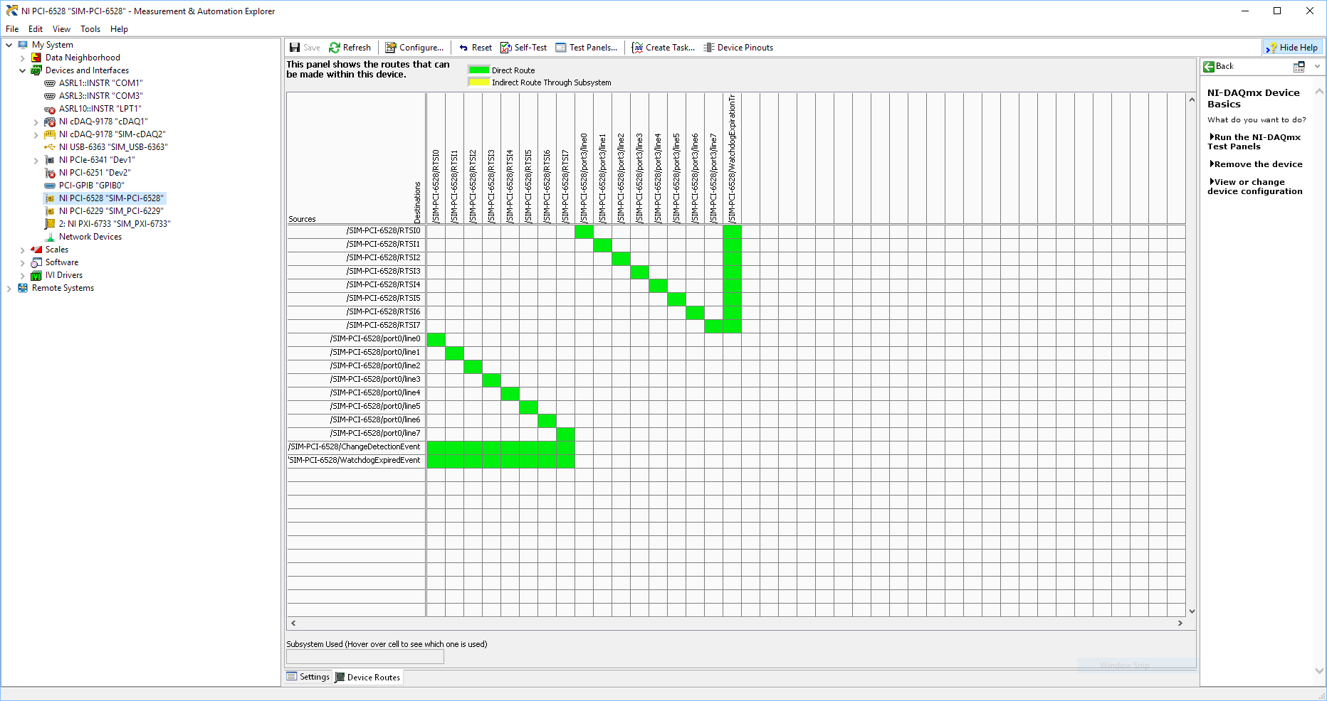
Probably not. Unless the routing plan is in fact reversed as it seems a bit sorta that. As stated on my system, you can route * of * a port of entry * to * RTSI, or you can route * of * RTSI * to * one output port. This does not make much sense to me, but that's what I see:
If the routing card * is * reversed, your only likely workaround without physical wire would be to generate impulses in question of port 3. It's pretty clear that 1,2,4,5-tetrachlorobenzene ports have no ability to interact with the bus timing, physical wiring would be the only option.
-Kevin P
-
I'm looking at the SMU 7857R. I would use the 8 analog inputs and the FPGA to do some annalysisy and DIO based on the best data. I was wondering if it is possible to also define a DAQ task so that all analog data will be made available to the host. Using a data acquisition task would be easier for me to have to write code fpga for use a DMA fifo to send back data.
Hi bcat!
A data acquisition task is only for devices Data Acquisition product supported by driver DAQmx as X-, M-, S-, maps E-Series. The boards of the R series are only supported by the driver OR RIO.
If you don't need pre-treatment on the FPGA so that you can distribute simple data through DMA on your host. If you are looking for an API for the comparable FPGA with the DAQmx API then please check the NI CompactRIO waveform reference library. You can also use the library for R Series boards. -
I use the SMU 4140 to measure the curves of voltage/current for the transistors - it sets a voltage & I read (not necessarily on the same channel). But I noticed a peculiarity in the data according to the current limit.
First of all, I get different results if I let him autorange device compared to manually set the current limit.
In particular, there is a current lag that occurs for differnent current limits.
In the attached file, the current is allowed to Auto for the Red data and fixed at 100 Ma for data in blue. [the axes are current drain source - ID- & door - Source voltage VGS]
Any idea what is the origin of the offset .02mA in the Red data?
Thank you for following up with an explanation.
Looks like this resource to answer your question:
http://digital.NI.com/public.nsf/allkb/EE869FC813944EAC862578F0005519F5
-
I'm trying to upgrade a SMU-8105 controller since the cost of a new controller is very prohibitive (University laboratories have limited funds). I have managed to increase the RAM to 4 GB by purchasing compatible Crucial RAM, upgraded to Windows 7 (32 bit) and migrate the operating system to a PATA SSD 128 GB KingSpec once it arrives. I am now researching other options available to improve the performance of the controller. It seems that the controller is based on an Intel i945GME (rev 03) with a 82801GHM (ICH7-M DH) southbridge chipset. Now, my understanding is the following:
- The Intel 945GME chipset has a bug in the RAM address which limits the total usable memory to about 3.2 or 3.3 GB. Therefore, there are very few benefits to upgrading to a 64-bit Windows 7 version. Is it a correct assessment?
- We could spend the CPU at a faster. It is clear that the chipset supports the family Core Duo, we could theoretically spend the T2500 processor T2700 processor. However, you can usually drop a mobile processor Core 2 Duo in the same taken on most motherboards. Dropping in a T7600 would give a fairly significant boost of performance (for example, up to 20% for single-threaded applications). Is there a reason that I could not be able to replace the Core Duo processor with the Core 2 Duo processor? Update CPU has a list of compatible processors, but apparently it depends partially on whether or not the BIOS supports. http://www.CPU-upgrade.com/MB-Intel _ (chipsets) 945GM_Express.html #cs
Edit: Added link to cpu-updated website list compatible processors.
I was able to upgrade the processor in the controller a T2500 to a T7600 and got a nice performance gain. I know that this is not a supported upgrade, but SMU-8105 is so old that it's more commercialized by NOR. At this time, is it really important? However, if you are on a budget you will find this controller on EBay for less than $500. You can then mix in a SSD, 4 GB of RAM and a CPU T7600 (about $150 in total) and get a very nice controller which compares well with the latest at a fraction of the cost.
-
Band bandwidth SMU for FPGA chassis
I'm specing on material for an FPGA FlexRIO system. The module FPGA and adapter, we will use has already been defined, a 7975R and a 5782. For our application, we will be streaming 2 inputs analog on a RT controller attached. From my understanding, these samples will be single precision floating point numbers, each of which is a piece of 4 bytes. Assuming that the 5782 max sampling rate is used, 250 MECH. / s, I think that I will need 2 GB/s of bandwidth on my SMU chassis.
Here my question, then, what SMU chassis should I consider? The SMU-1082 has "up to 2 GB/s per-slot dedicated bandwidth", but it is a real or theoretical number? Normally, I would just get the next thing that high, just to be sure, but there is a significant price difference on the way to the SMU 1085, which is also much larger I need. So I would like to save space and several thousands of dollars if I could get away with a 1082. Sampling does not quite to the max modules of adaptation would be acceptable, but I would be interested to know where about my maximum sampling speed would be.
Thanks in advance for your help.
The 1082 has more than enough bandwidth to stream data at a time to the analog inputs of a 5782. The 5782 has a 14 bit ADC with two channels that sample to 250 ms/s. These samples are returned as an I16 with the two least significant bits filled with zeros.
So assuming that you transfer all I16, rather than packing the 14 bits of data, you would have the following bandwidth requirements.
2 channels x 2 bytes/sample x 250 mega-samples per second = 1 GB/s
The 1082 a 2 GB/s of throughput dedicated per slot. The 7975 accommodates up to 1.6 Gbps streaming. I would recommend calling chat with someone, if you are looking for a recommendation on what type of chassis to purchase, but based on the requirements of streaming that you're fine with the combo 7975 and 1082, you thought. Just make sure you get a controller which can accommodate streaming speeds you're looking for. The 8840 is a good candidate.
-
generation of sinusoidal wave with smu
Is it possible to generate, for example, one 3 a 50 Hz sine wave with SMU 4138 or 4139?
THX
The DCPower API provides no screws to use blocks of power or SME like FGENs. However, it is possible to program the jury at the exit of the standard functions by translating the desired frequency and amplitude to a sequence of continuous output with delays of source is defined so that the output function the user selects is output on the terminals of the device.
The attached program allows you to use a NI 414 x, NI 4135/4136/4137/4138/4139 as a FGEN. As it is, the program is limited to a maximum output frequency of 5 kHz.
I have attached a version of the code for the current output and a version for output voltage waveforms.
-
Hi all
I moved this question here because it is a more appropriate Board.
I'm looking for measurements of current weak on my HAD and therefore seeks to including the guard on my DUT PCB assessment cables. I have two related questions on this issue.
1: the pinout of my SMU-4141 said that there are two pins on guard and I verified this with a DMM, they are linked and lead to the same level as the channel HI. However the cable recommended DB25F-DB25F low leakage cable only has one of these pins connected through guard. Is this correct or is there an error with my cable? I checked all 4 channels and they are all the same.
2: anyone know of any good information / best practices for custody of follow-up on my circuit board?
Thank you all,
Nick
Hi Nick,
Yes thank you, very good, moved to AE a year ago to SRI.
In order to have a reflection and a look at the wiring diagram (which I'm sorry to say that I can't send you in its entirety) and I think I can help with the confusion.
The cable we're actually talking about is not composed of coaxial cables, it is composed of twisted with son of drain and a pair conductive sheath. The son of drain are inert and not get connected to anything, so, leaving twisted pair and their sheaths. There are 8 twisted pairs and gaines in the bundle that gets wired on this connector, which means that 24 potential connections, with pin 13 no wired what whether that make up the number to 25.
Now bear with me I'm sure it's logical: twisted pair number is wired to the pins 2 and 14, which are the two pins of HI for channel 0 in and out. The shield for this twisted pair is then connected to pin 1 (a guard PIN). While guard pin protects both the two pins of HI.
Twisted pair two is connected as well: one half of the twisted pair is connected to pin 3 (LO sense), the other half is not connected and the shield is connected to pin 16. Now if I understand correctly, the son LO need not so much caretaking, so the extra yarn I guess looks more like a thread of drain here.
The schema for the cabling continues like this. Half twisted pair are the SIH strength and direction for a channel that is guarded by a shield wired to an agent, and the other half are wired with LOs and an additional drain.
I don't know why we didn't use COAX when help files, explains using the COAXIAL cable, but I suspect is has something to do with the cost (one of the AEs who graduated from the electrical eng said COAXIAL is much more expensive than the sons of the twisted pair, but he said also it is much more difficult to disassemble to weld so I suppose it would make many of these cable manufacturing) very expensive and difficult).
Now with regard to PCB stuff, I'll be honest, it's not some thing that we have a lot of documentation OR on, but of what google tells me, guard lines can be incorporated in a KIC and from what we have seen in the cable, it looks like we want to keep the HFD for both strength and sense. I myself am a physical grad for PCB design is not something that I've had too much experience with.
What is the next CSLUG meeting (also like the mascot of the group, sea slugs are beautiful!)? I introduce the CLD Summit in early September at the Newbury office if you go to that?
Thank you
Viv
-
SMU-5606 Enable noise Source Power
Hello! I'm writing a measure of noise figure using the ASB SMU-5668R, which has an SMU-5606 inside. There is a noise 28V output Source I can use to connect to a source of noise. I looked through the drivers NOR-DAMA and succeeded in finding a property node (niRFSA-> Device Specific-> 5606-> noise activated energy Source) where I can wire an enumerated type constant (enabled/disabled) to fight against it.
If I connect a DMM to 28V output and toggle this property node, I see not 28V light. Are there more code that must be used to correctly set up the source of noise the 5606 28V output? I enclose a VI test I use to solve problems.
Thank you!
Hello
You must add a call to niRFSA Commit.vi following toggle to validate the parameter (which is cached) hardware.
I hope this helps!
Kind regards
Andy Hinde, MBA
Senior systems engineer
RF and communications
National Instruments
-
Generating signals simultaneously on two channels (SMU-5451)
Hello!
I'm trying to generate 2 different signals on the two output port of my SMU-5451.
Signals transmitted from data read from the file of PDM.
I'm able to generate 1 1 channel signal. But I can't ' figure out how to complete the data for my 2 channels memory and let generator simultaneously press these data or their respective!
Can any help? Maybe an example?
Thank you!
Hello Mr. Gambini,.
You can find all the information to do this here:
http://zone.NI.com/reference/en-XX/help/370524P-01/siggenhelp/5451_ni_5450_multichannel_allocation/
Particularly:
"To write waveform data to two channels at once, you must first striping of the data. "Once the data are interleaved, call the VI niFgen write Waveform (poly) or one of the wave functions write niFgen with the channel parameter set to"0.1"
Kind regards
-
Capture images of BT-656 using VMS 3.2.1 and SMU-6544
Has anyone ever been able to capture the BT-656 video signals using a SMU-6544? The literature indicates it is possible, but we were hard press to make it work. So here, we check to see if one was at any time able to get this working. Thank you.
Erich
Hi, I believe you were able to solve your problem by working with one of our application as a hardware problem engineers. If you continue to have problems, feel free to contact support and to resume work on this request.
Kind regards
-
Try to calibrate a SMU-5162 to the Executive 3.6.4 Calibration using the sensor Rohde & Schwarz PNR-91. I so that he sees NEITHER Max, but for some reason any Cal Exec will not see it. I have the 3 software/drivers installed which is required:
Toolkit 3.1.0 PNR
PNR-NI-VISA Passport 2.4.1.0
NRP - Z LabVIEW Driver 2.32
Any ideas what I am doing wrong?
Thanks in advance!
Hi Troyl,
you use the old PNR-Toolkit and the passport of PNR-NI-VISA. To work with the new driver NI - VISA 14 +, please update your:
PNR Toolkit to 4.9
PNR-NI-VISA passport to 2.7.0
Link: https://www.rohde-schwarz.com/software/nrpz/
rsnrpz to 3.4.1.0 LabVIEW driver:
https://www.Rohde-Schwarz.com/driver/nrpz/
That should do the trick
BR
Milo
-
Isolation between channels SMU 5451
Hello
We try to use the exit CH0 + as a floating voltage source. Our instrument is the NOR-SMU-5451.
It seems that the SMA cable screen is difficult driven ashore by the analog output.
I can't find in the documentation it is possible to isolate the CHx outputs of Earth.
Does anyone know if this is possible or not?
Thanks in advance!
Hello
I looked in your query about isolation and it is not something that is possible with the nature of the card being the only complete reference.
Thanks for posting!
Kind regards
Will be
National Instruments
Engineering applications
-
Hello
Is it possible to have SMU 8880 be activated via the magic packet Wake-on-LAN?
Our installation program runs a Phar Lap ETS OS.
Kind regards
W
Hi WhizzWr,
Unfortunately, the operating system PharLap ETS does not support WOL functionality. I think it's possible with the SMU-8880 runs Windows, however.
Best regards
Maybe you are looking for
-
Update of the NXT software for windows 7?
Absolute 100% beginner full here on Robots. Opens a NXT Mindstorms NXT kit (that I bought years ago but never opened) to start from scratch and learn. Built the first model of robot 3 wheels and went to install the cd so I can plug the robot in my c
-
I can't change the read only files on my NAS unit.
I have a promise SmartStore MS4300n Network Attached Storage system that I have used for more than two years. I can access it from my Windows Xp and my 64 bit Windows 7 computer. Yesterday, I tried to move some files from my Win 7 to the NAS and I fi
-
Can I use a modem to wifi with a c720 chromebook AC usb3?
See above please. Bottom line is that the manufactured c720 supports maximum of Protocol wifi n. Theere are wifi ac usb3 modems on the market. Can be used on the c720/chromebook?
-
LaserJet 1300: Error when sending to print to the HP Laserjet 1300 printer
Hello I've recently updated form Windows XP to WINDOWS 7, then to Windows Pro 10. I have HP lasejet 1300 printer. It worked fine with WINDOWS XP. I had the problem of printing when I got Windos 7, but it was resolved by installing with force provided
-
my windows 7 final not a real... What can I do
Diagnostic report (1.9.0027.0):-----------------------------------------Validation of Windows data--> Validation code: 50Validation caching Code online: n/a, hr = 0xc004f012Windows product key: *-* - YG69F - 9M66D-PMJBMThe Windows Product Key hash: /