Square signal of amplitude increase Contineously
Hello
I'm new to programming. I posted a few questions on the forum and the people were very helpful. I thank all for their help.
I have a DAQ and I want to generate a contineously increasing the output voltage of a square waveform. Can someone help me in that. Can someone refer me to a few examples that I can see and change.
Tags: NI Hardware
Similar Questions
-
PtByPt square signal generator for output FPGA
I'm currently building a host vi in which I can choose to send a square wave or a constant value in the analog output of FPGA. I know this might solve using the square wave generator express vi in FPGA.vi, how ever, in order to save using the FPGA card, I want to use the generator function from signal square on the host vi.
The first problem I encountered was square wave generator outputs feature a table instead of a ladder, so can not connect to the output function FPGA I/O node. Then I tried square wave PtByPt. However, the functino description is a bit vague for me. What I get now is a constant value defined by amplitude instead of a square wave. If I set the amplitude to 4, then the wave is a continuous line with a value of 4, and if it's 4 or - 4 depends on the frequency I put. I don't know if it is caused by the definition of wong of the time parameter of the function.
Can someone help me understand how a square on host vi of output wave? Thank you.
Here's the same VI to 8.5. I hope that helps!
Gregory C.
-
Hello
I want to do a continuous waveform. There are samples and files online to do it, but I would like to be able to change the frequency of signals continuously, I mean something like a function generator. I try to use the channel of PFI in NI 6221, but it provides just the waveform with a constant frequency. I wonder if it's a good idea to use the channel of the IFP? I want to give 100 kHz square wave.
Thank you
Hi Saridar
Thisexample may be what you are looking for!
Concerning
-
Square signal of function generator does not have any straight edges
Hello, everyone!
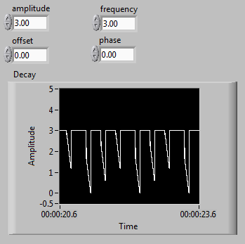
In my job, I need to see the charge and discharge of capasitor. I have to use a schema on the photo attached to power the capasitor, because I'm going to replace it with thermoresistor, requiring a certain exact current level. I use a square wave generator functions as a service. But when I built my diet on the prototyping card and connect the generator, edges of the square wave become geometries and there is no lag CC that I set myself.
Can someone help me to know what is the problem?
Thank you in advance.
Hello samewings,
I took a bit of time and studied your wiring diagram. Your reading of the oscilloscope, it seems that you've done well to capture the loading and unloading of response of a capacitor already. For your information, you can compare your readings of the oscilloscope to the document I have provided below. You will notice that your corners of square waves are rounded as the loading and unloading of curves that are visible when the charge and discharge of a capacitor. A capacitor charge and discharge over time. For this reason, the voltage you read in all of your circuit will show this curve depending on the time on the edges of your square.
-
Why it is so hard to generate the Master square signal?
Hi, I just can't do this work.
I want just a square of 1 Hz through Dac1 output
and receive it by cable to ach0.
Can't make it work...
Of course, this does not. You do not have to understnd dataflow. The top loop will not start until the low finishes and when the bottom ends, it immediately stops the upper loop. Remove the dependency of data between the two loops (i.e. don't wire from one to the other).
-
Results of increasing frequency generated unexpected behavior of the signal
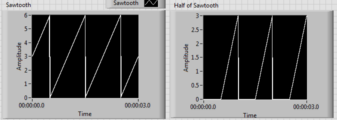
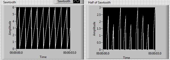
I'm generating a composite using a sawtooth wave, square, signal that produces the desired signal as shown on the left. Unfortunately, when the increase of the frequency beyond 1 Hz, I get undesirable results as shown on the right.
I tried to edit the news of sampling with no luck. I have also tried different methods to produce the desired signal. I noticed that before one of partial components of the final signal enters a relay, the increase of the frequency doesn't create unexpected results. Although, after its passage through a relay, the error starts happening. It seems that the relay is not suitable for higher frequencies, but I can't fix this unexpected behavior.
Frequency of 1 Hz:
Frequency of 3 Hz:
Another method that I tried was to use the "simulate arbitrary signals," even if I was unable to find a way to increase the frequency of the signal that results.
In addition, the signal has this grainy nature that I would like to make it smooth and continuous. Is this possible? I would like finally to reach a frequency of a few kiloHertz.
I have attached the VI.
Any help would be greatly appreciated. Thank you.
The problem has to do with the size of the block and when the relay actually sees the saw tooth cross the threshold.
Solve it, to perform a point-by-point check and build our waveform personalized to each iteration.
-
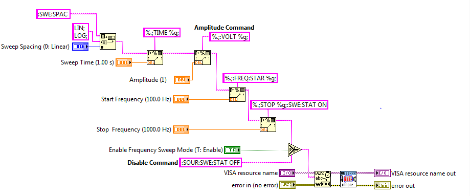
Sweep with Agilent generator of functions - increasing amplitude
Hello
I use a function 33210 A Agilent generator and I'm trying to generate a simple sine with constant amplitude sweep.
For some reason any amplitude increases during the entire scan. I used essentially the VI of scanning of the Agilent 33xxx example live
Only, I added the VOLT command to control the amplitude as described in the user guide. Hope you can tell me where is my mistake.

This phenomenon occurs if you scan the frequency manually?
-
square pulse generated with the NI PCI-6723
Hello
I generated a pulse biphasic square in Labview using a standard square wave generator and by stopping the vi to run after generating a full periodic square wave period. The only problem I have is that as soon as I stop my code, so once the square impulse had emerged, the analog output of the Council NOR remains at the same voltage as the last sample of the generated square pulse. Instead, I'd like the voltage is back to zero.
This is the same phenomenon that you see when you use the Measurement & Automation when you build an analog output and then you stop manually, if you take a look with an oscilloscope to output voltage, that it remains at the level you stopped analog signal.
I have attached a picture of a pulse square with 1V amplitude and 1250 Hz frequency showing that voltage level will not return to zero. If I try to add a sample more to the curve above, the tension instantly bumps up to 1, leaving me with the same problem.
Any thoughts?
Thank you
Alessandro
It should work.
-
variable phase shift between two analog output signals
Hey! I would drive two different piezo elements with an sine - / square signals and have a phase shifted output signals. After some trail and error, I was able to get a second analog output on my card PCI-6221 (using LabView 8.2) also allowed me to have different amplitudes for both signals. However, I could not output signal having a frequency different and most importantly to my request to have one of the signals variably shifted phase.
Thanks for the very useful suggestion. I have attached the file .vi installation I've run so far.
Hello!
A way to generate waveforms is using the analog waveform Toolbox. I created an example VI that is attached and that shows you a way to use the base generating function VI. I saved for LabVIEW 8.2.
I hope this helps!
-
generation of two complementary pwm signals using myrio
Hello, im working on a project and I need to generate two complementary pwm signals (when we go to 1, the other goes to 0) using myrio.
the problem with the blocks of myrio pwm is that when you set the market factor, the signal always starts with its high value. Can someone help me please?
Hello
You can create a Boolean square signal with chosen service and frequency cycle, create its opposite with makes NO sense and then send both signals via Digital Out vi (myRIO/Default/Digital Out) to two different outputs.
Best regards
-
USB-6211: analog input signal affecting another of the same map AI
Hello
I use the DAQ-nor-6211 map and DAQmx features to read a hammer and a signal of the accelerometer and then use other LabView functions to make the FFT of these analog input signals. However, it seems that the analog inputs where the hammer and the accelerometer are connected generate a kind of noise or influence in other entries of this data that is not connected to any other sensor acquisition board.
I've had different experiences in order to check if the problem is with reading the card: put the accelerometer and hit the dog in another table where the DAQ card table was located (to avoid the vibrations on the map and a possible noise), ai1 entry was logged on the differential mode on the dog and the ai4 of entry is connected to the output (z axis) of the accelerometer. The other 2 ai2 and ai3, entries that can also be read by my LabView program, are open (i. e., any other sensor is connected to the card). When the structure where the accelerometer is located is struck by the hammer, the signal of ai2 ("x axis" seen in the first attached document) has a curve (on the time domain) which initialize almost at the same time that the hammer and the a3 of entry has a weak signal, but with the swing as well as the signal of ai4. The document "hammer ai1 + z_axis connected_ _x_axis disconnected ai2 + y_axis ai3 ai4" images that I captured the chart created in LabView. On these graphs, it is possible to check on the FFT the ai3 signal and ai4 has the same behavior (with different intensities), and enlarged figure of time domain image, we can see that the signal of ai2 increase almost at the same time of the signal of the hammer (ai1). The signal picked up by the sensors are probably creating a sort of noise on open entries ai2 and ai3.
Another experiment was conducted to check if the signal from a single entry that may affect the signal read from each other near the entrances: the DAQmx task Create channel had a physical channel has changed: ai3 entry has been modified by ai7 (maintain the same connection mode: differential), and the results are visible on the second attached document. In the graphs obtained in this experiment, it seems that the entrance of the hammer (ai1) affects the signal of input ai2 and ai7, which are not connected. And the ai4 signal does not seem to influence the other inputs, because he has a different curve on the graph of the FFT.
The same experiment was conducted using the CSR connection (change threads and create the DAQmx Channel Configuration), but the results were the same as those found using differential connection.
Finally, if the output of the accelerometer is connected on the ai2, the signal of the other open entries ai4 and ai7 seem to be affected by the signal of the accelerometer on ai2 (last document attached).
Could you tell me if the problem I encounter is caused by the DAQ card with this information that I gave to you? And if the answer is Yes, do you know if there is a way to avoid this noise create in one entry on the other hand, it please?
Thank you
Maybe Ghosting or crosstalk? Just an idea.
-
generate a square on the analog output wave
I use a PXI-6229 DAQ card and I need to generate a square on ao0 wave. I'm programming in c# and have found an example of the expedition, which generates a sine wave. I need to be able to modify the function generator that was provided with the example of the expedition to produce a square wave 7.2 kHz with duty cycle of 50% and 2 v peak-to-peak. I enclose the code generator to function.
Thank you
After a lot of trial and error and adapt the example to generate a sinusoidal signal, I have the solution to generate a square signal of analog output. I enclose the code.
-
Good evening
I am trying to generate an output voltage and I am facing some problems. I am using an analog input voltage NI 9263 module, I have two sons (AO0 and COM) connected to the terminals positive and negative a BNC connector; I want to generate an alternating voltage, 60 Hz and amplitude of 1 to 5 V. Unfortunately what I measured with a multimeter is something always scaling, for example: if I generate a signal of amplitude 1 I measure 0.7 volt, if the signal is amplitude 2 to I measure 1.4 and so on. I would like to know if some of calibration is required or there are potential errors in what I do.
Thank you.
Sorry, but am not at all in agreement with this response.
A BNC connector has no impedance any of its own. The output impedance of a signal generator is determined by the circuit, not by the type of connector.
Anyway, even if the output of the circuit impedance is 50 ohms, it is not the reason for your reading. The mulitmeters input impedance is high enough does not create a voltage with an output drop rather low impedance. The reason is probably the difference between a peak to peak of current voltage alternating (AC) and the RMS value. In your case, probably the software defines a range of crete and an RMS value is measured by the meter. The effective value is always the peak divided by (root of 2) value.
See also
http://86.43.94.97/moodlecp9a/mod/glossary/showentry.php?CourseID=1&concept=RMS+voltage
-
I filter a signal of amplitude of the 0.2 Volt connection. It consists of pickup and noise of the line. How to do? Is the software filters are enough or I have to design a filter material?
Hi sukhiray,
If you have less than the full version of LabVIEW, there are several software filtering options available in the category of Signal Processing. You can configure your thresholds and the order of the filters and choose between the different types of filter. The choice between hardware and software depends on your needs and signal.
-
order a fan with USB6251 and the Daq signal accessory
Hello
I have a school using Labview project and the USB6251 connected to the Daq signal accessory card.
The Labview program must read continuous temperature (Ia 4 channel, internally) temperature probe connected to the accessory of Daq Board signals. When the temperature reaches an established value, then a led on the front panel should be lit and a singal output data acquisition should start a fan connected to the acquisition of data which cools down the sensor, then stops.
Would it not be possible to do something like that? Even if I generate a square signal and the fan only works on the State of the signal. The fan requires at least 120 mV DC current. I'm afraid that if I take these courses for the acquisition of data, I could damage the unit.
Thank you.
I guess you mean 120 current my DC
 . If you look at your spec of daq card, you will find that the current max are far below 120 my. This applies to the two analog out and digital out. Take a look at this site, it may be useful to some. site nice http://www.me.umn.edu/courses/me2011/robot/TechNotes/motorcontrol/motorcontrol.html . If you want the speed controller, you have two options PWM or voltage of the motor regulation.
Good luck

Maybe you are looking for
-
How to buy in app purchases in Indian App Store via iTunes e-gift card
How to buy in app purchases in Indian App Store using the gift card iTunes electronic? where to buy the e card for my online transactions?
-
original title: no control volume-a mystery Suddenly, I have no volume control. When I use the control panal its SNA Manager click "control of colum icon or I get a mess install no volume control. I have sound I have the latest Realtek. Whence ' vo
-
Missing EXIF data in the folder "Images".
I transfer my photos from my Canon camera to the default photos folder. OK so far. Each subfolder (for example, 2009_06_29) that contains the images is accessible by clicking on it. The images are displayed as icons (mini photo). OK so far. When I si
-
The documents folder is always developed when I start Windows Explorer - how can I change this?
I have read several posts that meet development and reduction of records, but I can't find any way to prevent this file either open, when I run WIndows Explorer. I did a print screen of the opinion I have open with and will try to find a way to put i
-
We have a server PE1950 Gen 3, we can look to install some SSD on. The SSD is crucial CT512MX100SSD1. This technique of the product: says he of a 6Gbps and will work with 3 Gbps. My question is, is the work of these SSDS with our server of gen 3 PE19