Static analog output without a while loop?
Hi all
Would like to know if it is possible to set up a card outputs analog instrument (with DAQmx I presume) to have a static/continuous output, without needing to use a while loop. I what would want to return a single value rather than a table or a waveform. It would be similar to option for digital IO cards to have static strings instead of strings of waveform. In the examples I've seen, he always seems to be a time loop is necessary, even if the channel is configured for a single sample, but I think it would be cleaner and easier to control dynamically without the loop (particularly if I run several screws in parallel). My particular application is to configure inputs and outputs analog, then runs different tests with other maps of the instrument. Please notify. Thank you.
GSinMN
No, you don't need a loop. A writing DAQmx for 1Sample game, it's all you need. Please include am image of the pattern block one of these examples. My guess is that the example is simply a way to accept changes in production without having to re-run the whole VI.
Tags: NI Software
Similar Questions
-
Retaining the last value without a while loop
Hello
I'm using LabVIEW 2013. My VI is attached. I'll send in a 'Curr. Random random numbers TestPlan Row"time. I'm eager to keep his last number, whenever this VI is not called and then reset the value to its new value whenever the VI is called again and a new number has been sent. Also attached is a screenshot at the VI.
Please note that I can't use a WHILE loop, so it must keep its value in a different way...
Thanks in advance for any help!
SM
Maybe a feedback node?
-
Stop and start the task in while loop
I try to start and stop an output meter (creates pulsed output) in a while loop and I don't know how this is possible. I have a while loop running who is taking measures from a digital compass. If my title is within acceptable limits, the outputs of the meter (2 of them to turn to the left and right) must be turned off. If the title is out of the acceptable range, let say too far to the right, I want to start one of my outings of the counter to activate the object to the left. The issue I am having is that if I put the block 'Start the task' in the while loop the system will try to start each iteration of the loop, even if it is already on. I don't know if there is a problem, but it does not appear effective from a programming perspective. I remember reading somewhere that stop and start tasks can really slow a loop. Any suggestions?
I actually just to understand it. If you use some if statements and the "fact of task is" block you can make it work.
-
Analog output on USB6008 in C ANSI does not work
I tried to program the analog output on a device of USB6008 under MSVC ++ 6.0 with the latest NOR-DAQ 8.8.
The lines of the example of the ANSI C program ' MultVoltUpdates - IntClk.c ' work very well with a device emulator, but not as soon as I try to access the real device of USB6008.
/*********************************************/
DAQmx Configure Code
/*********************************************/
DAQmxErrChk (DAQmxCreateTask("",&taskHandle));
DAQmxErrChk (DAQmxCreateAOVoltageChan(taskHandle,"Dev2/ao0","",-10.0,10.0,DAQmx_Val_Volts,NULL));
DAQmxErrChk (DAQmxCfgSampClkTiming(taskHandle,"",1000.0,DAQmx_Val_Rising,DAQmx_Val_FiniteSamps,4000));During the call to the last line concerning the synchronization setup, an error occurs:
________________________________________________________
DAQmx error: measurements: request the value is not supported for this pro value
Property.
Property: DAQmx_SampTimingType
You asked: DAQmx_Val_SampClk
You can select: DAQmx_Val_OnDemandTask name: _unnamedTask<0>
State code:-200077
________________________________________________________
Is there a work around?
Finally, I want to set unique values for the analog output voltage in a loop.
In commenting on the "DAQmxCfgSampClkTiming" call, no voltage is defined in a "DAQmxWriteAnalogF64" call to handle this task.
Thanks for the tips!
'DAQmx_Val_OnDemand' is not a valid option for "DAQmxCfgSampClkTiming...." and leads to errors of execution, if I put it anyway.
As an alternative, I tried in the meantime:
DAQmxErrChk (DAQmxCreateTask("",&AO_V_taskHandle));
DAQmxErrChk (DAQmxCreateAOVoltageChan (AO_V_taskHandle, dev + ao0 "",""-"))
0.0,5.0,DAQmx_Val_Volts,null));DAQmxErrChk (DAQmxSetSampTimingType (AO_V_taskHandle, DAQmx_Val_OnDemand));
DAQmxErrChk (DAQmxStartTask (AO_V_taskHandle));
DAQmxErrChk (DAQmxWriteAnalogF64 (AO_V_taskHandle, 1, 0, 1.0,-))
DAQmx_Val_GroupByChannel & data_v_out, & writing, NULL));
(data_v_out = 2. ;--> back: written = 1) not--> no measurable output voltageDAQmxErrChk (DAQmxStopTask (AO_V_taskHandle));
--> still no measurable output voltage
Any other idea?
-
storage of the data output of while loop
Hello
I have a data acquisition system set up to read the couple of a transducer. The output needs to be fed with an excel document, once the program stops running, or when a key is pressed.
with the current code attached, the excel document is created, but it only shows the most recent series of data. How to make the table to store all the data coming from while loop?
Ive only been programming with labview for two weeks, so chances are that it is something simple, but please help us in any case.
JM
To get what you expect, the Terminal output of table a while loop right click and select the option activate Indexing. Usually if you want to save data use queue to pass data inside the while loop to another loop/VI and perform data recording. For all that you have examples, please do a searc in LabVIEW help > find examples.
-
How to run a while loop continuously without iterate loop inside the fi, a condition is met
I enclose a VI that once the answer 28 comes the loop must stop and loop should continue an iteration. Can you show me a way for her
You can stop the loop when a certain condition occurs: http://zone.ni.com/reference/en-XX/help/371361H-01/lvhowto/add_cond_to_for_loop/
Add a register to offset for the while loop and to implement the feature as below:
-
HAVE multiple AO-synchronization-2 multiple while loops
Hi all
I want to characterize my RF circuit by using an additional narcotics control and map PXI-6229. I wrote a simple VI in Labview, which is almost similar to the example, multiple-HAVE-AO-synchronization, seen in LABVIEW. According to my VI, 4 analog outputs with different offsets dc, amplitudes and phase values must be generated to my RF circuit and 2 analog inputs must be acquired by this circuit simultaneously and continuously. But the problem with my VI is that I try to observe two diagrams at the same time to see the changes in signals generated and acquired. However, I don't see the two signals simultaneously. The second while loop, which belongs to the acquisition of analog signals, does not start while the first loop generates analog signals continuously. How can I synchronize these two while loops in order to observe the two parties in the diagrams?
I have attached my VI.
Thanks in advance.
T. Eray
Hi Eray,
I will be brief and I'll keep it simple. If I understand correctly, you have trouble with the data stream in LabVIEW. When you work in LabVIEW, you must understand the order in which the blocks (functions/nodes/structers) are run in LabVIEW - stream. Each block can be executed just at the moment where there values on each entry. This means that if the 2 blocks are connected with a wire, the 2nd block waits until the first ends its execution.
In your case, that means, this 2nd loop does not execute before the first loop (with the DAQ Assistant) ends its execution, because the son comes from the inside of the first loop, then they go to some DAQmx features and then DAQmx features they go to the 2nd loop.
In principle, what you could do is to put the content of the first loop, where you prepare the signal generated in the 2nd loop. Good course without the DAQ Assistant. Instead, you can use DAQmx writing in the 2nd loop.
Kind regards
Martin
-
To input analog shutdown when the analog output is completed and synchronization
Hello
I'm trying to get my LabVIEW program to send analog output to a computer and read acceleration using the cDAQ-9184. Chassis output that I use is the NI 9263 and the chassis of entry is the NI 9234. I generate a signal of white noise using LabVIEW Express signal generator.
The first problem I have is the synchronization. I had an old VI that has begun to measure the acceleration just about a second after the entry has been given to the machine. I used the LabVIEW tutorial on how to sync the analog input and output, only to discover that it does not work with two different hunts. Then I found another tutorial that shows how to synchronize different frames between them.
The second problem is the cessation of the LabVIEW program. What I want to do is to generate the signal and then simultaneously send and read the input and output analog, respectively. It is because I don't want a phase difference or any shorter signal for a direct comparison. But as soon as the signal is sent to the machine, I want the entry to stop analog playback and then then the LabVIEW program must stop. I want to be able to choose any length of signal to be generated and stop as soon as the entire duration of the signal has been sent to the machine.
I tried 'DAQmx stop', "DAQmx Timer" and 'DAQmx's task made?' and none of them have worked for me. It is also my first time on a forum posting, so I hope I gave enough information. I enclose my VI as well. The VI shows I read an entry for the analog input voltage, but I am only using this to try to get to the work programme.
I'd appreciate any help I could get.
Thanks in advance
Peter
Hi Peter,.
I have some recommendations for you that I think you will get closer to your solution. First of all, I assumed you meant that you had 1 chassis (cDAQ-9184) who had two modules in it (NOR-9263 and NOR-9234). My next steps are based on this assumption, so if it's wrong, please let me know.
For your first question about the synchronization, the code you provided is very close to what you need. You need to do, however, implement architecture master/slave for startup tasks DAQmx functions. To do this, you can add another frame to the flat sequence structure and put the master start task (input voltage) after the start slave (output voltage) task.
To manage your second question and that the program ends at the point where you, the first step is to get rid of all the logic that you use with the local variable of length of time. Rather than use this logic, just wire the node "task performed?" of "is task performed?" operate to stop the loop. This will cause your loop to stop as soon as the signal is sent to the machine.
I have some other recommendations for you that will increase the performance of your program:
(1) rather than writing on file inside the last loop, you can use the DAQmx Configure Logging (PDM) .vi. You will place this VI between DAQmx Timing.vi and DAQmx Start Task.vi to the task of the analog input voltage.
(2) after the last while loop, you want to stop the task and analog outputs as well with another DAQmx stop Task.vi.
(3) rather than using a local variable for the entrance of displacement and wiring it in the DAQmx Write.vi, you can wire directly from the output waveform of the wave to build function node.
That should help you get started in the synchronization of these tasks.
-Alex C.
Technical sales engineer
National Instruments
-
Redeclenchables/continuous to a custom waveform analog output?
Hello
I try regular output an analog signal using the box USB-6211 and Labview2009. I looked at various examples of waveform, including the retriggerableAO.vi example, but I can't seem to understand how to send a 'waveform' custom stamp (terminology is perhaps the question). In all the examples (including waveformbuffer), I ran across the single waveform, the options are sine, square, etc. Previously, I posted on this forum looking for hardware suggestions (link here) and explained what I try to do and got the big help. To sum up, I would like to read a 'waveform' from a text file, send it to the usb-6211 buffer and then continue to an analog channel. At the same time, I'll use the beginning of the analog task to trigger a digital signal once per cycle as well.
I got in what concerns the establishment of the waveform, but am stuck to figure out how to get into the buffer and setting the frequency, etc.
Thank you
Gabe
Hi Gabe,
Dennis is correct that it will take some room to modify the existing screws to fit your need. As he says, the Con Gen tension Wfm - Int Regeneration.vi Clk - no example provided with LabVIEW. In the example, it can be shown that there is a custom VI used to explain the problems that arise when a waveform of a given frequency to a frequency of sampling and outputs analog specified.
With all that said, it seems you want to read from an existing waveform file that you created and this waveform to an AO output channel. There are a few things that will be needed to know before proceeding:
-What is the waveform as you try to output (5000 samples, 10 k, 100 k, etc.)?
-What pieces of the size of the wave you want output (100 samples at a time, etc.)?
-you want to again and again, or simply run through once the waveform looping?
Assuming that you already have the waveform and will only step by step, here's what I would like:
-break the large waveform into smaller pieces of waveform of standard size
-import the waveforms in LabVIEW and create an array of waveforms
-bring the waveform in the example Dennis mentioned previously with automatic indexing enabled on the tunnel
-Remove the generator of wave functions existing the while loop
-wire your indexed table of waveform for the data of the VI DAQmx of analog output terminal
It is possible that you will have to play with the settings of your waveform and timing of your VI, but this should be a good starting point. Please let me know if something is not clear or if I have misunderstood your original message. Have a beautiful reast of the day.
Best,
-
Update an indicator of in while loop with event driven programs
I'm trying to update a chart shared by several events within a Structure of the event. I would like a change in value of a button (NOPE or OK buttons in the attached example images) causes the structure of the event causes a switch between the various outputs for the chart. In the example attached, clicking the OK button will send the graph random matrices, while clicking on the button NOPE will send constant tables to the curve.
As the process within the structure of the event is underway, I use a while loop within each of the different events in the event Structure. So there is a structure of the event, and each event have while loops in them which should update the chart outside the structure of the event (see attached images).
This does not update the graph, the graph remains static instead, why is this? How can I configure it to work as I described above?
In my view, a question is: How can I use the same stop button in both inside while loops. In the example images, I have two that are different, one for each of the different events.
Thank you!
-
How to set up the execution in a way independent while loops?
Hello
I hope someone here can help point me in the right direction for that. My system at this stage is still quite simple, I just data collection of 2 resistance probe and a pressure sensor, their output in the Panel before and sometimes to write. I have put architecture in place to call parallel loops running at the frequency I would ideally like to do. that is, I want the RTD to update every seconds and the pressure transducer for updating chaque.5s, I want to write to the file at a rate defined by the user and I want the Panel before updating a half second (correspondence with the pressure transducer).
Now, in the structure, I wrote, it should run all the while loop once before it can restart the sequence. Technically, the code works, but it takes ~1.5s to the RTD to collect and update and so the whole VI takes ~1.5s to complete.
I don't care if the RTD is slow to update, but as I use the sensor as a gauge of the cell pressure I need to know at a high frequency that the pressure is in the cell, and I don't want to wait 2 seconds for the information.
I know I'm starting to get into a much more advanced architecture for this and ive spent the last googler 6 hours trying to find a procedure for how it works but I can't figure out a way to have the whiles stop waiting for RTD loop finish. I guess that this is to divide the VI in several screws and construction of a library, but the resources I could find about it were not very useful for a beginner like me. If someone could point me in the right direction on where I should look then that would be great!
Thank you
Zach
Zach,
Because you created the tasks of data acquisition elsewhere, we do not understand how you have set up. Continuously, starting and stopping tasks may be slower than setting up of a permanent task and let it run.
You have not indicated that you use the DAQ hardware. It is often better to leave in the DAQ hardware clock set ignition rather than rely on software distribution. The pressure loop reads 1000 samples at a time and calculates their. If you're not sampling at 2000 s/s or faster, the loop ends late due to waiting for data. In two loops DAQ, you do not use the calendar information. Acquire the data in tables rather than waveforms.
The Dequeue functions in the loop at the bottom have no wait times for this loop will not iterate until all three queues have data. As the pressure loop runs faster than the loop of RTD, the queue of pressure slowly fills.
The upper and lower loops are vying for the data. The preview queue item does not delete data from the queue, but the functions of the Dequeue elements in the loop of the low fact. If data is deleted form the queue before the upper loop resembles it, it will never be saved. With your installation there is no way to ensure that you get all the data or that you do not read and record the same data more than once.
You don't have anything set up to stop one of the loops. You use the Cancel button to stop your VI? If Yes, STOP! Other aprticpant on the Forums said: "using the button abandon to stop a VI is similar to the use of a tree to stop a car.» It works, but can have unintended consequences. "Things like closing of files, freeing up the queues, by closing the task of acquiring data, and other things can occur when the program is interrupted. You do not shut down your computer by pulling the plug. Stop your program also neatly.
Ok. I have highlighted some of the things that can keep your program to run as desired. What can you do about them?
1. you probably don't need call loops. Normal so the loop should be good enough.
2 put a stop button on the front panel. Put the terminal in loops (bottom) and connect it to a function to send a Notification and the status of the Terminal loop (stop sign). Put wait Notification functions in each of the other loops. Put a period shorter than the time loop minimum on all of them if the lops can work.
3. see the comments above regarding the DAQ bed material.
4 use the Dequeue timeouts to adjust the pitch of the loop the loop where the data is used. Also make sure that all data is removed. You need to think about your time together and what are the bottlenecks. Except if you expect this system to grow to much larger dat sets, I probably acquire ALL data (pressure and RTD) at the same rate and reduce the displayed amount by the average like you do for pressure data now. If you want different final data rates, just average different amounts of data.
5. it might be useful to learn how to work the State machines. Display, averaged and recorded files could be managed in a loop by a simple state machine while allowing for more flexibility in the calendar.
6. Another good reason to consider a state machine is that initialization and shutdown processes can easily be handled in the corresponding States. At this point you do nothing with errors. A state machine would enable you to handle errors (for example, the cancellation of the selection of the user files) without stopping the program.
Lynn
-
Using of FPGA VHDL IP and analog output
I use a system with Labview 2014 PXI. I've got Labview FPGA to program and run the card PXI-7854R.
I have the VHDL Code I want to use to control an analog output of the card. I use the IP integration node for this now but I also tried it making the process CLIP and still have not been successful. The problem that arises is that the IP integration node must be in a timed loop, while the analog output indicates that it cannot be put in a timed loop. Is there a way to provide an output of VHDL analog outputs of the card?
I tried to embed a loop timed within a while loop, but it still does not work.
I can't download the VI due to the policy of the company, but suppose I'm generating a sine wave in my VHDL code which must lead to the analog output of the card (the actual wave is company owner information but it is generated by a glance to the top of the table as a sine wave VHDL would be).
In an attempt to work the problem I retried import CLIP of the HDL code in a new project in Labview and VI. I'm still not sure about why it did not work with each other when I tried it.
For anyone who seeks to solve this problem:
I basically used this tutorial for the process CLIP: http://www.ni.com/tutorial/7444/en/
It also explains the differences between the CLAMP and the IP integration node.
-
Trigger start analogue does not work for the tasks of the analog output
Hello. I wonder - what someone has tested the trigger mode analog start for continuous output voltage-. example of VI under hardware input and output - analog output folder in the Labview.
My camera's SMU-6358, who has two lines APFI and supports analog trigger. Although it is very difficult to find information on the use of analog trigger for analog output of the tasks, what I've learned so far is to connect the interested analog trigger signal (such as an external noise) on both the AI channel which is used as a source of relaxation (ai0 in my case) and a two-channel (APFI0 in my case) APFI.
During the test the example above vi, any level of relaxation that I put (even with 0), the task of output did not work at all. No error message is returned either. Just for your information, I do physical tests, not only the software simulation, so no signal means no signal.
Any help is appreciated!
I have here is that the solutions to this issue, just want to say thank you to all who have helped me on this subject.
Use the analog analog trigger output tasks, make sure that the trigger signal (input HERE) is connected to APFI0. There is no need to connect the trigger even signal to ai0 if you do not want to save the trigger signal. However, if you do not want to save the trigger signal, connect the trigger signal to both ai0 and APFI0 with a signal splitter. In the latter case, the task of the AI shouldn't take the same trigger that the task of the ao. This means that you can start your registration with or without a trigger, while leaving the task of ao wait a trigger of some signal. This is useful in a situation that you only want to generate ao task to a certain trigger event, as when a signal reaches a certain level of sound pressure.
-
Detect the change of the value in While loop
Hello
I recently took a code example in examples of using Labview and I'm putting the analog output through my data acquisition card 4461 pxi. I want to have a continuous waveform, but being able to change the volume and the waveform will adjust automatically and be issued through the card.
In the code, I have everything first to open a .wav file and write it. While playing continuously through the while loop, but I want the signal to change automatically when the volume is changed. I know that I should probably use a structure of the event but the while loop, I use to play the signal will never stop unless the user presses stop so it would play permanently in a structure of the event even when the value changes (I tried).
So now I try to see if there is a way to make my time stop loop when the volume value.
You must correct the issues (forget the events if you are not sure of them):
1. If wire you the digital volume to the wall of the while structure, then the whole in structure only tell that one value that happens on the node and will not read new values.
2. to read the new values, move the Volume Terminal inside any building (which will shock your other code that depends on it), or use a local Variable inside any node.
3. to check if the value has changed, you must compare the value to the previous value. To do this, use a shift on the while loop register to store the previous value and then compare it to the new value with the function "not equal?". Wire the Boolean result of this to the conditional Terminal.
A better way for you might be to wrap the multiplication and Analog Write function into the while loop so that you're constantly replaying the waveform and it's continuously being re-scaled by the volume value. This will mean your volume control is being continuously polled (once per waveform playback) and used to scale the waveform each time. You'll need to figure out how to stop, send and play the waveform once per iteration of the while loop by bringing the Stop VI inside too.
-
How to write constantly to analog output and read from analog inputs
Hi all -
I had a question about writing continuously to analog output reading simultaneously an analog input.
It's my first time to post a message to the community, so please let me know if I made mistakes.
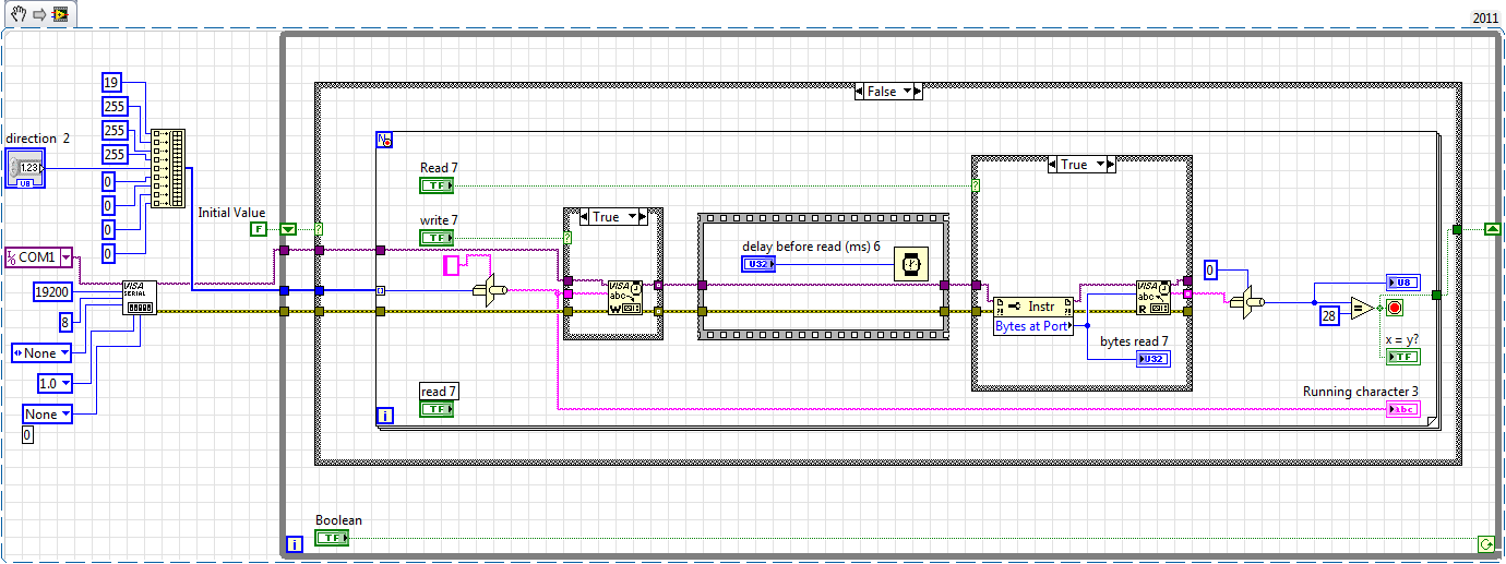
I use Labview 2011 with a NEITHER-DAQ USB 6215.
I'm looking to generate a waveform and write it continuously in an analog output. It is then connected to an entry on the acquisition of data, where I am trying to sample the analog signal. (I realize, there is a system of trivial, but I'm hoping to build on it once I have run).
The task of reading from the analog input works fine, as I tested it in several other cases. I have a problem writing to the analog output.
For this task, I tried to follow the "Gen Cont Wfm Clck Int' VI to generate the wave form and start the task. I then try to write to the output of the analog timed loop. However, it does not seem to transmit a signal and doesn't give me any errors.
I have attached the VI but also a screenshot.
Please let me know if anyone has any ideas. I would really appreciate the help!
Thank you
Peter Borgstrom
We will review your tasks one at a time. First of all, the task of generation/Analog output Waveform. Generate you a waveform (I'm unsure of your VI if it is a fixed waveform or not) and send it to a defined output function to produce a waveform continuously, using N-channel and samples of N (where you set not these previously). You should not put this inside has timed loop, as the DAQ hardware has its own clock - if you simply put it in a while loop (with a stop to break out of the loop), the loop will call the function for the first points of N, wait until all N have been taken out, then call it again to another N points (up to what you press Stop).
Now, suppose that you have the output connected to a load voltage (say a decent resistance). You can wire the input terminals of your A/D converter through the same load and set up a similar analog input loop, running in parallel (i.e. in its own independent of the OD loop, while loop). You pourriez start together (with, say, a merged error since the initialization code line loops HAVE and AO become lines of error in "loops of sampling" described above), but you might want to delay loop (a little) the AI so that the OD has a chance to set the voltage before the bed.
I hope this helps.
BS
Maybe you are looking for
-
How can I enlarge the letter of 'Postvak In' column, not emails
I'm working on an Apple and the Thunderbird with Postvak In column, Verzonden etc., is such a small lettertype it costs energy to focus. If I can enlarge always be fine. The email itself is not a problem. It's easy, but it's the entourage.Hope you ca
-
I removed the toolbars so I could see below thinking that I could easily get them back, but I can't. How can I get back them? I can't even put a new web address now. Or refresh a page. Or go to the front/back. How can I solve this problem?
-
Last download for Satellite C70D-B-307 - 10 Windows display driver
Please, I would like to download the latest version of the display for Satellie C70D - B 10 Windows utility. How can I do? Thank you
-
After trying to run chkdsk /f and still having no luck, I went and did a repair on Windows XP. It worked finally. Then, I went and did the 52 windows updates and then it happened to me again. I am now afraid to do updates on this computer window as I
-
Run the system restore, but has not restored
Tried to launch system restore on different dates in the past and the system response is always the sane who:no changes have been made to your computer. System Restore could not restore your computer about to restore specified. Select a different res