Storage of samples of several analog channels (life-long)
I use a USB6356 to read 5 analog channels (more digital input port A)) simultaneously until you press a stop button. The idea is to represent all the signals captured on a temporal scale after the acquisition.
I am convert and storage of the 2D array that is captured in each iteration of the loop in another 2D array in order to have an output of 5 table lines (one for each input signal).
However, Labview can not handle so much treatment in so short a time table (I think that the main bottleneck is the 2D Transpose VI table) and accidents very soon (I have to kill the entire process and restart Labview). Is there a better way to do this?
See you soon
Your problem is that you have horrible memory management here. Whenever you add in the table, more memory is allocated, then the table is copied. You are basically out of memory.
1. use samples of N, N channels, 1 table D of waveforms for your Read DAQmx
2. change your chart to a chart and move it to be inside the loop. Maintain chart, a story, so you can still see the X last samples on it (1024 by default).
3. save your data in a file. I recommend using the DAQmx configure connection before starting the task. This allows the stream directly to a TDMS file for further processing.
Tags: NI Hardware
Similar Questions
-
How to use DAQmx Read to measure several analog channels
I have two analog inputs using USB 6221 and I want to measure the voltage of each of them. I use vi DAQmx-read and I select input analog, 1 sample, several channels, but I do not know how to connect several channels at the entrance of the physical channel.
Hello, Bernadette.
For reference - I would recommend ad DAQmx questions here:
NEITHER Forums: Multifunction Data Acquisition
http://forums.NI.com/T5/Multifunction-DAQ/BD-p/250
There are several ways to add multiple channels for a fast task-ni.com look for "select multiple channels DAQmx" gives me this like the hit albums:
2X8D7F5Z knowledge base: How can I select more than one channel of NOR-DAQmx LabVIEW?
http://digital.NI.com/public.nsf/allkb/A3A05920BF915F1486256D210069BE49
Hope that helps!
-
How to write table values to analog channel?
Hi all
If I have a table of values, is it possible to write these values as an analog voltage and then stop writing when he arrives at the end of the table? If so, how does do this?
I have attached my code that generates a table of frequency swept sinusoidal voltages and I write that out to my analog channel, when I consult my output however, I get the same display of sinusoidal repetitive time and time again. I expect for example:
writing of wave of 1 Hz, 2 Hz, 3 Hz etc...
but I'm getting the 1 Hz wave over and over again, I selected samples in the sample clock and pretty much done a lot of trial and error and still no luck
 . Any help would be appreciated!
Daniel
Hi Daniel!
Take a look at this example (you can find examples of LabVIEW):
Gen CONT tension Wfm - Int Clk - no Regeneration.vi
Here is an another VI I did (see table). It is slightly different from the example of the LV and it should help you.
It could be that useful...
Julien
-
Exception on the creation of a second task with Analog channels?
I'm getting an exception '{error =-50103 = "is reserved for the resource specified. The operation could not be performed as specified.\n\nTask name: _unnamedTask<5>\n\nStatus Code:-50103 "} ' when I call Control(..Commit) on a task with Analog channels, I just created."
At the time of creation, I have another task set and running in the "we demand" move that uses another set of analogue channels in the same card to acquisition of data (NI6229).
Is there a limitation on the number of tasks that can use analog in the channels of a single card?
Thank you
Go Paul
Because the analog inputs share a unique clock, you can have only one task running. You can have as many channels as you want in a single analog input task, however.
-
I use Labview 8.5. and the NI USB-6210 device.
I want to display the analog channels over the continuous acquisition.
I can use the table of waveform or waveform graph. Waveform allows you to eat a history buffer. This function is very interresting and useful for my system, but I can't change this value to programming (if I do not mistake!). So, I was wondering if I can also use the waveform graph, but I do not have how to make a circular buffer to replace function "history buffer. I have to use the waveform as a data type.
What is the best solution for my problem? I would like to know if my solution is good (graphic use of waveform) and if anyone has a solution to make an effective circular buffer with the waveform data type?
Thanks in advance, best regards, Daniel
There is an example that comes with LabVIEW called "XY table". It shows you how to create a history for a XY Chart buffer. The size of the history can be changed on the fly. You can adapt the VI "graphic buffer XY ' to work with a data type of waveform." This type of data consists of 3 elements: start on time, delta t and table of values. The only thing that you should be buffering is the array of values.
-
SONY BRAVIA 50 "no signal message for find analog channels
I bougth a BRAVIA 50 "and everything has worked perfectly, but suddenly the TV sent no signal message can not find the signal of channel or something like that. I bougth TV on December 2012 and this 4 last January that happened. What?, because I could see 7 channels before that. I tried to reset the original settings and I read, but nothing seems to work for some tips. The other features work well. It's just the analog channels. I hope someone knows the solution. Thank you
I bougth a BRAVIA 50 "and everything has worked perfectly, but suddenly the TV sent no signal message can not find the signal of channel or something like that. I bougth TV on December 2012 and this February 4 this year that happened. What?, because I could see 7 channels before that. I tried to reset the original settings and I read, but nothing seems to work for some tips. The other features work well. It's just the analog channels. I hope someone knows the solution. Thank you
-
How to use several collaborators channel of BBM BBM?
He said we can use several collaborators for the channel of BBM surveys for the new update...
but I can't find any source to the place where to use it?
Thank you
Jay
Channel of BBM of multiple contributors: BBM channels now supports several collaborators channel via the web client; makes it easier for the owners of BBM channel 1 million to manage and publish new content.
The web client:
-
I'm trying to change the example Acq Cont & chart voltage so that it shows two analog channels and wrote both of these strings in a file. I was able to do so and record for at least 1 minute two days ago, but yesterday when I tried to run the vi, it would only write 20 seconds no matter how long I let him to save. I went back to the example originial vi this morning to try to run that one, and he writes too only 20 years. It will show the space for the number of seconds during which I left it to save on the time axis in the PDM Viewer, but there is no data plotted. Is this due to a setting I can I unconsciously changed in LabVIEW, a framework to the viewer TDMS itself, or something else entirely? I've only been recording noise so far to test my vi, but I can post one of my TDMS files if this will help.
After playing with other ways to read the files, I found that the viewer TDMS was simply not read all samples in the file more. Fortunately, I managed to find my own solution (very simple)!
-
How to pass the time of capture of several pictures by a long period of time?
Is there a way to change the capture time (in OUTPUT) of several files into a long period of time?
When you select the photos you want and go to the metadata - edit Capture a moment, you can change the capture time in increments of hours... I need to spend time to capture a few photos per years... Is this possible at all within LR?
If you select two or several images, we'll have the "most selected" - image it will be brighter white. Usually, it is the one that you select the first.
-
Using the SMU-6368 module, I would like to monitor the analog signal on multiple channels and trigger on several channels - relaxation and acquisition channels is all on the same device. Probably going to be sampling at 200 kHz and more. FM LV 2009 2012, with SV toolkit in Windows 7.
If SW trigger is the only way to follow, there example code shows how to manage the block size, etc.. ?
jkessler,
Yes, the example was in 2012. I didn't get what you asked for in your first post because I didn't know you wanted to ANY channel to trigger acquisition of all channels. It is not possible at the hardware level, because you cannot specify four channels as the command source. This will be implemented in the software. I recommend the reading of all four channels and neglecting data until you determine that one of the channels reached your threshold value.
Kind regards
-
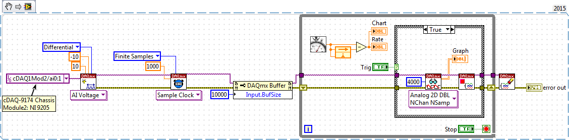
Not able to read 4000 samples the analog channels of cDAQ module (module NI 9205)
Please check the chart bloack (FALSE Structure box state a wait with 20ms function) and attached the code (saved in LabVIEW 2015).
On executing the code and using the button 'Trig', I can see only 1000 samples (for each channel) and not 4000 examples.
Please help me to understand what I am doing wrong?
Entry of son "4000" to "samples per channel" Schedule VI DAQmx. The default value when unwired is "1000".
-
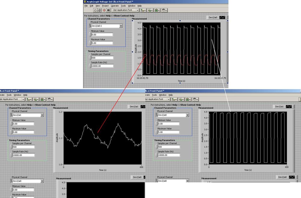
Several analog inputs seem to change any of the other (details DAQ: 2120 BNC and 6062E)
I use the BNC 2120 DAQ board connected to the data acquisition card 6062E to record two analog inputs. An entry is connected to ai0 and the other at ai1. Example vi: "Acq & graph int clk tension" has been used to measure the two entries with the value read NChan NSamp vi (channels being dev2 / ai0:1). The output is the top graph in the image. However, this seemed a bit strange to me that one of them should be modulating with a different frequency. When I record both entered individually (two in low pictures) they are indeed different since the entries shown in the top graph.

Why this would be the case, and how can I overcome this to measure the real signals?
Thank you!
The E series card takes the samples as soon as possible. Thus, for example,.
If you have 16 analog input channels but you only read of
channel 0 and 1, the map will show the channels 0 and 1 right
After and then wait 14 'ticks '. What's that little run-in
the origin of the afterglow.
I think you can get the card to wait a certain
number of ticks with a property node. I have attached a screenshot. You
can find the property node in the palette of functions >
Measurement of e/s > NOR-DAQmx > node Timing. Expand it
Property node so there's two entrances. The properties are in
Left click on the node and going more > converted >
Its properties delay units and sampling clock delay and delay that
you want.If the phase is important so the above is not the best
the option because it causes a delay in phase. So, if you need true simultaneous
sampling, then you will need different hardware. The S series is everything
simultaneous sampling.Or, rather than the Delay property and delay units, try the Rate property
find more > converted > rate.If this is not
work either, you can move the second signal source to, say, AI8 and
Connect everyone to the ground. Readings for these, but just do not take into account
the data. In this way the ADC will sag to the ground at the time where that can happen
the second string in the way so that you should not see this frequency
ghosting on the other channel. -
Interleaving of samples: two outputs analog (tables with different lengths)
CHAN                   AOCHANNEL1       AOCHANNEL2       AOCHANNEL1           AOCHANNEL2       .. .and so on
SAMP                   * * * * *           *              * * * * *              *           .............and so on
Hi guys, how could I go on the interlacing of two arrays of different lengths in a two-channel analog output?
In the illustration above, for example, I like to write 5 values in channel 1, followed a string of unique value 2 and so on...
I use DAQmx library controls to achieve this (not LabView).
I am able to write unique values each time a task is opened without any problem, I was wondering if I can interleave the berries so that values are buffered and tasks are performed with greater haste.
best regards,
Ravi
target met: I've made the following changes:
CREATION OF TASK 1
CREATION ANALOG_VO channel 1 & channel 2 in TASK 1
CONFIG. CALENDAR OF TASK 1CREATED some TENSION with SAMPLES interleaved pre
WRITING TASK 1 VALUES
TASK 1 STARTED
DAQmxCfgSampClkTiming(taskHandle1,"",SAMPLING_RATE,DAQmx_Val_Rising,DAQmx_Val_FiniteSamps,2*SAMPLE_SIZE_WX) -
Synchronization of two inputs frequency meter with several analog inputs
Hi all
I'm relatively new to LabVIEW and I'm trying to collect data from multiple sources with calendar sync on the acquisition, but I can't understand. My problem is that I have two inputs frequency meter, an optical tachometer reading one pulse per revolution and a max flow meter machines with a 12000 k coefficient. I can't find a way to synchronize the calendar with my multiple analog inputs. I tried to first get the speedometer to synchronize with the analog inputs following the example linked here. (https://decibel.ni.com/content/docs/DOC-10785) So far every time I run it I get an error on the DAQmx read timeout or an error "several sample clock pulses have been detected" (see image). It seems if I slow the way to down to say 10 hz and make sampling rate ensure that the tachometer signal is more than 800-1000 rpm (13-17 Hz) before starting the VI then the program will run without error until the ROTATION speed is below this threshold, then the "sample Multiple clock pulses" error occurs. The code is attached below.
Does anyone know of a better way to synchronize the entries of frequency of the counter with analog inputs? I would like to have a VI that can display 0 RPM (and possibly 0 flow as well, but I think I need to understand the timing of a meter before I have add another, because it seems that I can't have two counters to the same task). Any help on this would be greatly appreciated.
LabVIEW version 13.0
Chassis cDAQ-9178 with NI 9401 for both counter inputs and NI 9205 for the analog inputs.
Thank you!
Richard
I know the error requires to restart the task at least (this particular error puts the material in a State that cannot be recovered from during execution of the task - I've been down this road before) but I'm surprised that you would have to delete and re-create the task altogether. And then I had to do this to workaround other questions in the past. It is awkward and should be considered a bug, if this is indeed the behavior.
Honestly, regardless of this bug, the way the material dealing with the situation of several sample clock edges makes measures of sampling frequency clocked essentially unusable for purposes of synchronization (in my opinion anyway) If you encounter a more slow than your sample clock rate. You are supposed to be "synchronization" of the measure, but it really no longer applies if you have to restart the task over and over again (if you must delete it or not).
Workarounds can get kind of creation (which isn't really a good thing). For example, you can configure a measure of implicit frequency to keep a buffer of frequencies and use a leader board task (source is the frequency signal, sample clock is the sample clock HAVE) to establish a correlation between the index of your buffer of frequency for singing HAVE sample clock.
Best regards
-
Sampling motion controller analog voltage (from a load cell)
Dear nstroud,
Or the other of these commissions should work for you. You can configure one of the axes for engines step by step closed loop analog feedback and then put in place the other 2 axes as slaves to the first with a debt ratio of 1 to 1. This would cause all 3 of your axes to behave in the exact same way. This transmission is made on the card, and you should not see any negative impact on the axes update rates. The specified sampling rate should not be a problem either. The update of control loop period is definable in the adjustment of the loop tab, and for stepper motor axes, it determines how ofter the step generator is updated. The default for this value is 250 milliseconds. The 7340 user manual also lists the scanning speed of demultiplexer of analog input @ channel 25 microseconds / activated.
So you would be actually sampling and update the engine generator step much faster than 100 Hz with analog feedback on axis controllers.
See this knowledge base for more information about the configuration:
Analog feedback with a stepper motor:
http://digital.NI.com/public.nsf/allkb/AB3CCA7FBFAD749A8625713B001D8581?OpenDocumentBest regards
~ Nate
Maybe you are looking for
-
Qosmio F50-114 - how to use the video cable?
HelloI have a Qosmio F50-114.I want to capture video via the video cable supplied with the computer. The computer came with a video component cable software plug-in (1 x 3, 5mm - 3xRCA white/red/yellow). The only place in the manual stating that cabl
-
1024 MB of memory for Qosmio G10-137
PA3313U-1M1G is for 1024 MB of memory 333 Mhz DDR partnumber. can I also use 400 or 533 Mhz DDR memory for the Qosmio G10 - 137 met a Centrino Intel Pentium M 755 2, 0Ghz 2 MB cache 400 Mhz processor?
-
Can satellite P300 - I create a RAID with 2 HARD drives?
Hello I recently bought a P300 - 1This, with 2 x 250 readers also. I was wondering if it is posible to create a RAID 0 between these 2 drives... can someone help me with some comments? Thanks in advance!
-
AO532h e-recovery - backup file not found
AO532h (Win 7) e-recovery successful (better than ever). One works a program to find the backup files "before recovery? This file was new in... C:/backup/public/.../log/channel.ini: [PATH OF LOG]C:\Users\Public\OEM\Acer VCM\Log[UDP ONLY]OFF[LOG LEVEL
-
Win 7 Updater failure on new install
Cool led Win7 (32 bit) installation and activation on refurbished Dell Inspiron 1545. Activation by phone successfully did. System will not update. The only successful update was the Windows Update Agent 7.6.7600.320.