Sync to external trigger in conjunction with a nearest pulse frequency device fixed...
I am writing an application running a scan frame. One axis of the scanner runs at a fixed frequency. I use a scanner high speed 5105 to get the data. The slow axis of the scanner is controlled by a servo with an analog input. I have will probably use an M-series card for analog control, but can also go with a 6713 (output only) or another Board. Fixed frequency Analyzer provides a clock line, I want to use to drive the 5105. In addition, the analog card must be synchronized in this. The entire system should be able to accept a trigger external devices, as it starts scanning at the edge of clock on next line.
I'm not quite sure about what would be the best way to do it. External triggering from other devices will be an indeterminate pulse width, so I can not just use it as a portal for the line clock. I am reluctant to do it in software (IE via the detection of changes on a digital line) because I want to be reliable started the next clock pulse. I have taken into account things like a counter/timer with a relaxing break, but which could lead to drift between the narcotics control and frequency scanner fixed. It seems just more complex that I think it should be, and it feels like I'm missing a simple way to do it.
Any suggestions?
Hi cshl,.
Good to know - the 5105 has a duty cycle of tolerance of 45-55% (mentioned on the page of the form), so that is why you cannot change clock speed from 3 to 12 MHz on-the-fly (though if you make small incremental updates over time, it would be theoretically possible).
With the additional information in mind, you might want to try the following on the 5105:
Use the external trigger as a trigger of departure (arm of acquisition).
Use the line as a signal reference clock (with a position of 0 samples for reference ~ 7500 are after initiation).
The problem with this is that you will have to re - trigger on each line - 5105 has a 2.4 rearm us time (also mentioned in the page on record). If this is unacceptable, another way that I can think of is to use a clock to external reference in PLL internal clocks of the bezel to. If you can provide a stable, a clock accuracy 50 ppm which is synchronized with your scanner within reach, would solve the problem of drift over time without having to re - trigger on each line (only acquire data continuously). This clock frequency must be between 1 MHz and 20 MHz in steps of 1 MHz.
We have no Council can take in an external variable clock up to 12 MHz (on-the-fly), but if you wanted to compromise a little bit the 6115 can enjoy up to 10 MHz, and has no obligation to cycle to 45-55% so it's maybe interesting look in.
As far as AO goes, I assumed that the clock line is declared after the quick scanner has completed his turnaround (ideally you do not update the zone of OCCUPATION during the lead time). If you have a signal Analyzer that you can use instead probably easier. If not, our peripheral series M and X series (but not the series AO 67xx) offer reference clock feature so if you go with the idea of reference mentioned above clock it may be easier to simply PLL the clocks together. These cards in a PXI chassis or are they PCI form factor?
I don't know what you mean by the sticking point about the need for two triggers. I think the idea is that we use the external trigger to arm the 5105 and clock line to trigger each record. However, if you do not need to generate a pulse double based on the clock of your line then you can use counters to do (our counters are redeclenchables with time to rearm in the ns range).
Best regards
John
Tags: NI Hardware
Similar Questions
-
IMAQ Grab Acquire.vi error when you use an external trigger on a card NI PCIe-1433 (sync problem?)
According to my recent post on getting up and running with the NI PCIe-1433 camera link card, I ran into a bit of a snag.
When you use the internal trigger on the camera, everything works 100%. I can view all the data from the camera in MAX as well as in the labview project. However, whenever I have set the mode switch is where things start to fall apart.
What I have confirmed:
-Camera is switching between inside and outside triggering.
-NI PCIe-1433 camera link card is set up properly. While in external mode, I can trigger the camera by using a function generator and check the wire to the MAX. Everything works fine.
When the unit is in external mode, the function Acquire.vi enter IMAQ - my mistake VI. The error is:
Code :-1074397150
The possible reasons for a timeout.
Now, I have it set up so that a mistake here will not end the LabVIEW file. Sometimes, data of interest makes however (about every 10 seconds-ish). So what seems to be the case, it's that this external trigger signal is not in the lineup when the clamp is attempted. Is it possible to synchronize these? May reference the trigger signal external sort in my LabVIEW project so that the clamp is performed only when that trigger impulses?
So I solved my problem. He was in time. The external trigger that I used for the device was simply too slow. I was initially using a trigger from 2 Hz to be able to view the values changing on LabVIEW probes. But it was enough to get enough data to move above the camera cable to assemble a picture and kept it in time. Travel up to 9 kHz solved the problem. No adjustment to the camera settings or LabVIEW code was necessary.
-
problems with several hr2000 + external trigger mode
I hope someone can me halp on this problem:
I need to acquire spectra with two hr2000 + and a nirques256 with labview external trigger mode.
The external trigger mode is done by another pc and also the train of pulpse generator.
If a trigger after I'm going to generate a 100 impulse every 20ms for each device through a dedicted Council.
If I only work with ghosts at times things works fine and the system is very stable, BUT if I work with two or three spectres by now I have a really strange (maybe for me) problem with the timeout.
This is due to an incorrect number of pulses:
If I work with two device then I need to produce pulses of 200 each 20ms but my spectrometers provide data every 40ms, but I need to equip every 20ms
If I work with threedevice and then I need to produce pulses of 300 each 20ms but my spectrometers to obtain data each 60ms but I need to equip every 20ms
Thus, in this way, I lose the synchronization of the three councils.
An options may be to use a dedicated pc for each device
I acquire the signal via usb and the problem is maybe duo to the bus
I think maybe the problem is duo to the vi block! Maybe I can use single istance at times when I call the procedure
Thank you
I just solved the problem: it was a problem with reentrancy
Default LabVIEW use not reentrant execution
-
initialization of the fgen on external trigger
Hello
For NI_Virtual bench with the BNC switch, we can trigger the function generator to start the square wave? I mean, I want to relax, so I have the beginning of the square wave
You cannot trigger the function generator to start in response to an external signal.
However, you can export a signal only pulses when the FGEN starts the external trigger BNC. You can do this with the entry point to 'Dig deeper the Signal to export'.
Kind regards
William Earle
OR R & D
-
From a ReadWaveform on an external trigger?
I have a DigitalMultiChannelReader that I need to start reading a waveform when a change of external line. For example, I want to read Port3 lines 3 and 4, when PFI5 is high for a number of samples.
readWaveformTask = new NationalInstruments.DAQmx.Task ();
readWaveformTask.DIChannels.CreateChannel ("PXI1Slot6, Port3/Line3, Port3/PXI1Slot6/4", "", ChannelLineGrouping.OneChannelForEachLine);
() readWaveformTask.Timing.ConfigureSampleClock
"",
samplesPerSecond,
SampleClockActiveEdge.Rising,
SampleQuantityMode.FiniteSamples,
samplesToCollect);
readWaveformTask.Stream.Timeout = 1000;
readWaveformTask.Triggers.StartTrigger.ConfigureDigitalEdgeTrigger ("PXI1Slot6/PFI5", DigitalEdgeStartTriggerEdge.Rising);DigitalMultiChannelReader reader = new DigitalMultiChannelReader (readWaveformTask.Stream);
TODO: How to make the player doesn't start not the task here?
drive. ReadWaveform (samplesToCollect);The above code will start the task and start playback of the waveform as soon as 'drive. ReadWaveform (samplesToCollect)' is called.
How can I trigger a waveform acquisition using an external trigger?
CurtisHx,
In fact, even if the roads of the device shows a direct link between your PFI line and the trigger in MAX line, it only means that there is a possible link between these lines. You will still need to manually connect these terminals, which can be done easily with the method DAQmx connect terminals. If you need a detailed method explanation, you can find it here.
-
LabVIEW statechart module of data acquisition error external trigger
I have a 2 loop vi is the acquisition of data of a data acquisition instrument loop and the second is a loop to run my statechart of. I would like to respond to an error in device of acquisition data if it occurs in transition out of my current state in my diagram States-transitions and enable management of custom unique business mistakes. My States-transitions diagram is synchronous and send it external trigger.vi funciton will not work with it. How to achieve this? In addition, there is some confusion about this literature in http://zone.ni.com/reference/en-XX/help/372103F-01/lvscconcepts/sc_c_callervi/ at the bottom of the page it saidNote sending triggers for synchronous charts is optional. If you do send triggers, LabVIEW sends the NULL trigger for transitions. If you send a synchronous statechart triggers, you can send these triggers to the caller VI. »
Is it possible to do this and if so how with the synchronous statechart?
Thank you, it should work for me
-
Hi all
I use a Board PXI-5422 generator of finished generation mode signals to generate an external trigger signal (PFI0) about every 5ms. There is a nominal 1.7µs delay of the input trigger for the start of the generation. That in itself isn't a problem (I can compensate for the delay), but there are up to 50ns jitter on this period, which is a problem. Does anyone know if there is anything I can do to minimize this jitter? (Incidentally, PFI1 exhibits the same behavior, but it is not a surprise)
Thank you very much
Hello GVR123,
I had a glance at the manual for the PXI-5422 and I found the note for the ' delay of start CH 0 analog output Trigger "which is indicated as"65 sample clock periods + 110 ns. With this information, I calculated that
1.7 - 0, 110 = 1.59
and
1.59/65=0.025 (bulk)
that points to a clock of 40 MHz. So I guess that's what you use.
25ns deviation (40 MHz) each side (50ns total), you see the expectation, as there is no way to ensure that the trigger falls exactly on a rising edge of the sample clock.
I hope this helps.
Kind regards
Michael S.
Technical sales engineer
NEITHER UK & Ireland -
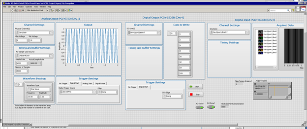
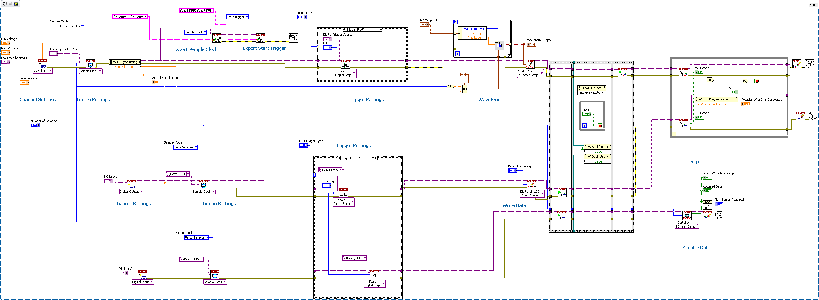
Several synchronization AO-DO-DI via DAQmx, external trigger devices
Having trouble getting the digital input to trigger analog output unit.
I have 2 AO cards (although I'm testing only with 1 device AO)
2 cards DIO - using one for output, one for input
All 4 cards are connected via a RTSI cable, and the cable is correctly condfigured in MAX, all 4 devices added to the cable.
I consider the AO the 'master' unit map In this test, I plead for a finite number of samples, and I'm outside triggering map AO.
As you can see, iI uses Signal export, export the AO and AO Start Trigger sample clock to DIO cards.
I'm using Labview 2012 on PC Windows 7.
The digital output is waiting for the AO trigger and appears off the coast of the AO sample clock synchronizing.
The digital input expires if I only fire at the time, so he does not expect relaxation.
any ideas? I tried all kinds of combinations.
Never mind! I solved the problem with digital input without waiting for the external trigger.
I just had to set the time-out waiting-1, so that he would never expire, and so he will wait for the trigger.
-
Acquisition of a sequence of images based on an external trigger.
Hello
I have a photonfocus MV-D1024E-160-CL-CMOS camera. I'm generating a square signal of a NOR-DAQ. I want the camera to image acquisition on each falling edge or rising edge of the signal. I've seen examples related to IMAQdx drivers to get a sequence of images using an external trigger like this, but there is no examples for the IMAQ. If anyone can post a few examples, it would be really useful. I saw the example of component snap off and tried to use it. But I think that if I use the encoding that is used in this example it will only launch the sequence rather than what I want. Thanks in advance for anyone who can help me in this regard.
Hello
Have you acquired images triggered in MAX when using the pulse width to determine the exposure time? It is always good to make a step back with these changes and make sure things are running at a more basic level.
-Zach
-
analog input external trigger 6015
Hello
I was able to configure my 6015 to accept an external trigger to start a measurement of analog input (with a # set of samples and freq). However, what I want to do is to set up so I can send a 20 kHz signal to the trigger, and whenever the trigger detects the signal, the device would take a measure of the tension of each of the two channels. He would then save this memory on board and allow me to read the data later. That's what I can't figure out how to do.
If he put in place such as I have an asynchronous callback and read data after each pulse, it takes too much time in my application. I want to get a measure for each external trigger pulse (the freq may vary higher or lower, it's why I can't put just a freq - I need to use the trigger) and these data saved in memory on the card for me to pick it up later.
Is this possible with the 6015? Another tip? If so, can you please show a few snippets of code in VB.NET or c# .NET?
Thank you
Joe
Hey Joe,
I think that your application should work fine with the 6015. I mentioned only the buffer size as previous your post said 'I want... these data stored in memory on the card to grab me afterwards,' and especially supported in NOR-DAQmx devices (including the 6015, PCI E Series, the new series X PCIe and PCI M Series) don't work that way. They have permanently transfer data in a buffer in the memory of the host throughout the acquisition PC, and they have enough buffer on board to avoid negative/overflow buffer overflow errors at their maximum supported rate
Brad
-
External trigger for a workflow
Hello
How can I start a workflow with an external trigger as a PowerShell Script?
concerning
Denis
Using the REST API, take one on my scripts here for example:
-
I have an ipod touch 128 GB... but I'm almost to reach its maximum.
I want to do is buy a new ipod touch 128 GB and add new music without synchronizing the entire library to it... I have 2 ipods in conjunction with the other copies of the other.
is this possible?
What should I do?
Matt
When you get the new iPod, you can use iTunes on your computer to select and synchronize the music you want on it, in the same way that you synchronize your current iPod - your iTunes will recognize them as different devices and will remember your choice of synchronization for each, it will not (unless, for example, you restore the backup of your current on her iPod) put the same content on both.
(I asked for your post be moved to the iPod Touch forum, where you have posted is the iPad forum use.)
-
This external modem will work with Satellite L500-1XL, running Windows 7
Hello
When in Spain, I need to use the dialing up to the internet through Telefónica.
I guess that the L500-1XL is not an internal modem?This external modem will work with the L500-1XL running Windows 7?
Thank you very much in advance for your help.
A
Hello
You re right Satellite L500 doesn t have an internal modem, so you need an external.
I think you can buy every modem that is compatible with Vista. Alternative ask your favorite computer dealer or authorized service provider
A friend got good experience with USRobotics 56K modem like this:
[USRobotics 56K USB Faxmodem USR5637 | http://www.amazon.co.uk/USRobotics-56K-USB-Faxmodem-USR5637/dp/B0019LZCEI/ref=sr_1_1?ie=UTF8&s=electronics&qid=1269253039&sr = 8-1] -
I try to sync a new phone 6 s with tunes11.4 and receive an error message saying that the phone cannot be used because it requires a newer version of itunes. I've updated the phone and itunes. can anyone help?
Sorry, iphone and itunes.
-
Jitter in response to signal generator of digital dashboard by using trigger nor tclk with digitizer
I've written a VI that uses NEITHER tclk to synchronize a generator (PXI-5422 named FGEN1) and a digitizer (PXI-5122 named DIGITIZER1). There is also a clock card TIMING3 generating a digital camera.
It seems that can probably be explained by the way TCLK to synchronize, but I don't understand all the details. Could someone help explain this to me?
You are right. NOR-TClk ensures that all synchronized devices start at almost at the same time, to the same sample clock, with timing very tight. Sometimes, the level of synchronization with the devices OR TClk-synchronized beats at the level of the synchronization of the instruments of some competitor channels in the same device. But this is not free, there are compromises and added additional jitter for trigger response time is one of them. Here is an attempt to explain why:
When you use NEITHER-TClk and send a trigger, the devices will respond to relax on the next cycle of the clock once made the trigger signal to the device. Let's say you have several devices all of them even configured with the same clock frequency. You block the signal of PXI_Clk10 using their PLL, so they drift out. But each unit's clock edge will be off, clock +-0.5 cycles. If you send a trigger to each of them, they will respond on the next clock cycle whenever it is, after the arrival of the relaxation to each device with different propagation times, whatever they may be. You get a single clock cycle of jitter on reaction of device to set it off.
When you use NEITHER-TClk, several things happen: all devices are locked on the PXI_Clk10 signal to eliminate drift. The device clocks are then adjusted to a period level secondary clock. Very very tight. Then a clock signal common, slower called TClk is produced inside the devices. All the generation of trigger are delayed to be sent to the next rising edge TClk, and all consumption trigger is delayed to be received at the next front descending TClk. This way you make sure that propagation delays don't mean one of the devices does not react to the trigger until the next clock cycle.
That's why you see jitter above the reaction time of relaxation. When you add devices with different clock settings, so the frequency of the TClk can be slower for a divisible frequency in the device clock frequencies everything is possible. This causes the trigger jitter of reaction time be even slower!
I hope this helps you understand what you see.
Maybe you are looking for
-
How can I set my homepage to a new request tab rather than "suggested" or "white"?
With the latest updates of Firefox, the tabs have changed. In the past, I was able to have a new tab open to my homepage (google), but seem to now have sites either empty or suggested/frequently visited. Although this sounds like a minor problem, he
-
I can't get the face time is someone of another trouble.
I can't say unable to connect to a time server error face
-
I have a mini-tower with windows OS computer using the Firefox browser, it started to run slowly, 3Mbps, while on the same machine using for example the download speed is about 6 Mbps, which is what I used to get with Firefox. Oddly enough, I have an
-
Satellite M70-337 random startup failures
Hello, I hope someone can help with this problem. In the past months, my Satellite M70-337 (18 months) began to refuse to start. Sometimes it works, sometimes it doesn't. When that happens, it will be often blue screen, reboot, and then work fine. Th
-
M58p 7479-RS2 Small Form Factor PC - recommendations for the operating system
Hello I'm unable to work on what to get for this old computer operating system (produced in 2008 I think). The closest model to what I can find, Lenovo website is the M58p 7479-RS1. It shows the firmware several updates and a BIOS update but I need a