synchronization-2 acquisition channels
Hi all!
I work with the following vi. to acquire the data of different channels. I have a device USB-6009 where I am reading data and independent, I'm generating a string containing data in a Boolean control, that I built myself.
I'm saving the data from both channels into a single file PDM. What I realized by looking through the data collected from tiara, is the storage of the data of the two channels does not start at the same time (the difference is very small).
Is it possible to avoid this? In this case, I'd appreciate your help.
Thank you very much in advance,
Miren
(Exactly simultaneous) simultaneous sampling analog input is not possible with the USB-6009. There are essentially two types of analog sampling that can be done with any Board/card/hardware DAQ. 1) simultaneous (or independent) sampling, or sample 2) overall. The difference has to do with the type of analog-to-digital converters on the map.
Simultaneous (or independent) sampling (that usually lists the rate of samples/s/Channel) has several analog digital converters for each channel and can therefore acquire each channel at the same time.
Aggregate of sampling (listing generally at the rate that some samples/s) was generally an analog digital resource, and each channel must 'share' the sense of resources only a channel can acquire a sample of data at any given time. If the rate of "samples/s" is shared between all channels. If you sample 2 channels, the resource analysis on these two arms as fast as she can to acquire the two samples (one each way), but there is always a delay between each sample (that delay must be equal in contrast to devices sampling sample/sec speed).
I hope this helps.
-Alex-
Tags: NI Software
Similar Questions
-
get the values of the different acquisition channels
Hello everyone,
I finished my project and I want to do something and I did not how. I am acquising three signals from three different pressure sensons with the use of the DAQAssistant configuration to acquire form three analogue ports (there is a screenshot it below) and after it is shown in the same graph (second picture below).
This works fine, but my problem lies in the fact that I want to measure the maximum value and the value of the minimum pressure of each channel and always it is measured the first of them. I divided the measures in time-slopes as it is shown in the last picture. I have tried every single Vi of part manipulation of the function range signal, but I'm still not in the way of their use or I'm totally wrong actuing in this way.
Could someone give me a hand?
Thanks in advance.
Best regards
Miguel.
Really, we do not have enough information to give you good advice, but I can give you some generic advice. If you want the max and min an array of values, values use the Max & Min table from the palette of Array. Unfortunately, the DAQ assistant returns the type of dynamic data, which can be either a table of waveforms or waveform unique depending on how you do. Configuring your DAQ Assistant, it seems you are getting a picture of waveforms, but to use it as a form of single wave. Just after taking the data, convert your dynamic data type data type in a table using waveforms the DDT express VI in the Express-> palette of data manipulation. It would probably break a lot of your code, and it's a good thing. Broken parts are parts that are probably causing you problems. You can now use the index table to get the individual waveforms to the table and get elements of waveform for the picture of the waveform data. Use this table with table Max & Min to actually find your max and min values.
Alternatively, you can use Split Signal of the Express-> palette Manipulation of data to split your output into three unique waveform signals. Each of these signals can be plugged directly into the table Max & Min (LabVIEW will be script in the necessary converter). However, I highly recommend that you do NOT. It leaves you the problem that your data type is not defined yet, as this is always a type of dynamic data.
Also note that the use of globals as seen in the pictures of your code is a bad habit that can lead to all sorts of problems. However, I can't offer a lot of advice on how to fix it without the rest of your code (Tip: will probably involve some shift registers). Please post your screws if you have questions, so we can offer the best advice.
-
Hi, I tried to sync files between my laptop and a pc on the network. Am not able to set up a 2-way synchronization. In addition, not able to set the location of the folder offline on my laptop
Hi Anand Singhania,
Thank you for using the Microsoft Windows Vista Forums.
In Windows, sync (short for synchronization) is the process of keeping files in two or more locations matched with each other.
In two-way sync, files are copied in both directions, keeping files synchronized in two different places. Whenever you add, change, or delete a file in both locations, the same change occurs in the other sync location. It's okay if you have made the changes on a computer, a mobile device or a folder on a network server; the same changes will be made at both locations. Two-way synchronization is commonly used in work environments, where files are often updated in multiple locations and then synced with other locations.
Where can I sync?
Sync Center is the place to go to synchronize your computer with network folders, mobile devices and compatible programs. Sync Center can keep automatically your files and folders synchronized in different places.
Open Sync Center by clicking the Start button, tap all programs, accessories, and then clicking on of Sync Center.
Sync Center is a feature of Windows that allows you to keep information synchronized between your computer and files stored in folders on network servers. They are called offline files because you can access them even when your computer or the server is not connected to the network.
For more information, see work with network files when you are offline.
See the links below for more information on synchronization.
Sync Center: frequently asked questions
http://Windows.Microsoft.com/en-us/Windows-Vista/Sync-Center-frequently-asked-questions
How to maintain your information is synchronized
http://Windows.Microsoft.com/en-us/Windows-Vista/how-to-keep-your-information-in-sync
Sync Center: recommended links
http://Windows.Microsoft.com/en-us/Windows-Vista/Sync-Center-recommended-links
Please post back and let us know if it helped to solve your problem.
Kind regards
KarthiK TP
-
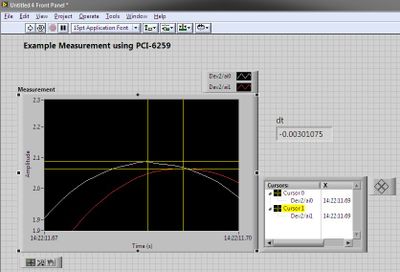
Synchronous channel multiple acquisition USB-6259 (phase measure)
Hello!
I want to create a user-signal (1 k at 20 kHz) in SignalExpress, generate it with the case NOR USB - 6259 BNC and measure with the same device after that the signal has passed a DUT I need the answer for a fixed term.
For the moment, I'm trying this: I connected the output via a Y-coax analog (length 1 meter) to TWO analog inputs.
Because the input channels have been grouped with the add a channel button, the data acquisition should occur almost synchronous.
However, sometimes the phase response is zero (cause as expected the two signals must be equal), but sometimes it "jumps" (especially when I am running the new project) and increases or decreases linearly on the frequency (so there is a time difference between two measured signals).
I don't think that running is the problem here, because referring to the manual, it's about some µseconds and I have not yet change the range of voltage between input channels. Furthermore, the magnitude response is fine.
I has not yet perform to synchronize the input channels with the output of the channels either, but first I would be recognizing a solution for the entry-entry-synchronization, (I don't mind if it is implemented in LabView).
Thanks in anticipation, Daniel
Hello Daniel,.
the M-Systems Series DAQ using a switch to sample multiple channels. So you have to take the time to switch into account when
you do measures such as phase shift of two signals.
I took your project Express of Signal but also created a LabVIEW VI to double check, and you can see exactly the same lag between the two
sampled signals. If you want to measure the true phase differences, you have to use a device of simultaneous sampling like S or DSA series devices (there are more a few others).
concerning
MArco Brauner NIG.
-
Using the SMU-6368 module, I would like to monitor the analog signal on multiple channels and trigger on several channels - relaxation and acquisition channels is all on the same device. Probably going to be sampling at 200 kHz and more. FM LV 2009 2012, with SV toolkit in Windows 7.
If SW trigger is the only way to follow, there example code shows how to manage the block size, etc.. ?
jkessler,
Yes, the example was in 2012. I didn't get what you asked for in your first post because I didn't know you wanted to ANY channel to trigger acquisition of all channels. It is not possible at the hardware level, because you cannot specify four channels as the command source. This will be implemented in the software. I recommend the reading of all four channels and neglecting data until you determine that one of the channels reached your threshold value.
Kind regards
-
NOR-DAQmX hardware synchronization for module 2 OR-9223.
Dear all
I use NEITHER cDAQ 9184-2 NOR-9223(1M) analog acquisition module 6 input channels of the sensors of acoustic emission (frequency of 20 to 400) with external signal conditioning.
Please please let me know how to synchronize using NOR-DAQmX? NOR-9223 does support hardware synchronization?
Thanks and greetings
Luong.Tran
Hi QuanLuong.Tran,
here http://www.ni.com/white-paper/4322/en/ you can find how to trigger and synchronize the different channels. It should work.
Best regards
CaravagGIO
-
Synchronization of the RIO based PCI cards
Hello
I have two cards PCI based 7833R with me. I would like to synchronize the two analog input cards with microseconds accuracy.could please, someone of you suggest me what is the best way to synchronize the two PCI analog input cards?
Early response will be highly appreciated.
-Niasse.
Hello
RIOCards synchronization:
In my application,.
- FPGA cards available: 7833R (1) and 7833R (2).
- Card1 will act as a master and card2 will act as a slave.
- 1 continuous square pulse of s will come from MasterCard and the same will be fed to another digital entry of the same card so card slave.
Channel connection details for the synchronization of two maps of FPGA:
Card1 (Box1) DIO1 must be connected to DIO2 card1 (box 1)
Card1 DIO1 (Box1) must be connected to the card 2 DIO1 (Box2)
- Rising edge of the square pulse is detected in the two cards. At the time where climbing aboard detected, acquisition will be launched in both maps.
- Every minute a rising edge is detected in the two cards for the synchronization, then acquisition will be launched.
I hope that helps!
Kind regards
Nicolas.
-
analog and digital data synchronization
Hi all
I would like to help with what I seek to accomplish, if you don't mind much.
I'm trying to synchronize the acquisition of analog and digital modes using a common trigger that launches both types of data collection at the same time. What I've done so far, is wasting his time trying different combinations to gather examples of LabVIEW 2011 on the synchronization of data - namely the 'Multi-multifunction-Synch AI lu Dig Chan.vi' and 'Multi-Device Synch-Analog Input-Finite Acq-Analog Start.vi.
I tried to combine the two, because one contains digital and analog, the other contains the trigger for multiple tasks.
I guess I should place the trigger (either digital or analog-eventually I will want to choose) then call the "Get Terminal name with device Prefix.vi. But from there I'm not sure wheter to connect the name of the terminal of the sample clock digital channel or a digital leading edge of the digital chain trigger.
Also, the way it is wired now I get errors at the local terminal name, so I don't know exactly where this terminal must come from.
I try my best, I could use a little help, I have attached my attempt with the examples that I speak to you.
Thank you.
Hi beefcake.
The CtrInternalOutput internal output line is used as sample for your digital output sample clock source clock. If you change the settings for your CO Pulse Time is Dev1 and your digital output is Dev2, you will notice that the name of the product terminal would give Dev2/CtrInternalOutput. So what you get here, it's as well as the digital output device sees his sample clock, instead of the clock itself.
If you just want to use a digital/analog input as your trigger, you should do something more as in the example above. Do you use multiple devices, or are all your lines on the same device? This example is more complicated because it is synchronization of signals on several devices.
Looking at how this VI is wired, you can see that the digital signal triggers the analog signal. You want the analogue signal must be started first, so that when the digital signal triggers the analog task is already running and can trigger immediately. If the digital task started first, it can trigger until the similar task had started, and they do not exactly trigger at the same time.
I hope that clarifies things. Kind regards
-
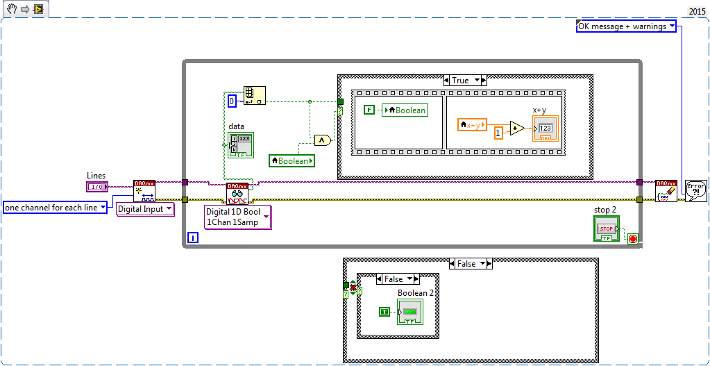
How do switch you between multiple channels to indicate which channel to acquire the data from?
I'm trying to builld a VI where I can have an option to enable or DISABLE multiple channels depending on the modules plugged into the chassis and then acquires the data of the channels which are turned on and where other acquisition parameters do not change. Is there any specific/switch where can I do this? Please answer as soon as possible. Its quite urgent. Thank you
You use DAQmx? To change the assignment of the data acquisition channels, you must close the currently open session and then create a new session with the new channel definition. So the order of execution:
Create task or virtual channel - read - clear task of triggering and synchronization of the configuration - set new channel list and to create a task - read - clear task, etc...
-
synchronize S 6110 PCI and PCI-6250 M series
I would like to sync between a 6110 S PCI card and a PCI 6250 M acquisition.
The first question is: do I need a RTSI cable to connect two devices?
Is it possible to use a single analog trigger (sent to channel the PCI6110 PFI) to start the acquisition on each card?
I need this information before buying the RTSI cable.
Thank you very much and sorry for my bad English (I'm Italian).
Silvia
I have a problem. I would like to synchronize the acquisition between two serial S PCI6110 and PCI6250 M-series devices.
I try to use an example provided by NOR, but it does not work.
The master device acquires the signal, the slave does not work. I also use an analog trigger signal to start the acquisition.
I enclose my VI.
Please, help me. Thanks in advance!
Silvia
-
Easy one - Show 6 entered a digital channel
Hello
I have a Setup with 3 LEDs which, within each of them is 2 led, so total I have 6 flashing LEDs. I got one of the sons of the signal 6, connected to my digital channel P0.6 on my DAQ 6351.
I would just get these 6 signal showed separately on a chart.I tried a number of things, but none of them would show them separately - how can I retrieve my DAQ.mx digital input 6 signal?
I have delete my project for these chart I tried to create an overview.
Thanks in advance
That makes no sense at all. You need 6 different lines to 6 different data acquisition channels.
-
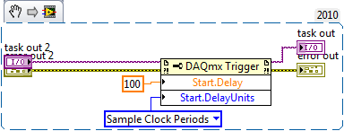
How to synchronize or trigger OR-DAQmx devices in LabView
I'm using LabView 2009 with a cDAQ-9174 chassis which includes an NI 9263 analog peripheral and an NI 9222 analog input device. I learned in the examples that I can synchronize the devices at the same sample rate. But I'm looking to sync devices such as the exact moment where I start to acquire input channel 9222, the 9263 begins to generate output. Secondly, I am interested to know when to use just this material, is it a way to very precisely to trigger a device turned off each other with a certain delay. So in summary I am interested in two behaviors:
(1) to synchronize an output channel 9263 to an input channel 9222, such as the beginning of a measure of analog input 9222 triggers a 9263 analog waveform output. and,
(2) have the analog output of the 9263 beginning for example EXACTLY 100 samples (provided that the sampling rates are synchronized) after that the 9222 starts to collect data. In other words, a trigger delay.
I guess that preference for it in hardware such as no software delays occur. Is this possible using these devices? Or do I need an external synchronization mechanism?
Thank you!
Hi tzoom84,
Back to your original question,
(Make 1) and (2), I don't think you should use counters.
Shipping example LabVIEW 2010\examples\DAQmx\Synchronization\Multi-Function.llb\Multi-Function-Synch I - AO.vi is probably a good starting point for 1). (Possible problem: If you use several engines timing to HAVE at the same time, the hypothesis of this example that the task of the AI "AI/StartTrigger" is not valid.) If this proves to be a problem, you may need to replace the name of Terminal get with device Prefix.vi with the trigger DAQmx > Start.Term property and add a call to the reserve of the task.)
For 2), add the trigger of DAQmx > Start.Delay and trigger DAQmx > Start.DelayUnits properties of the task of the AO:
If you really need to use counters, you can do without the NI 9401 using cDAQ1/_ctr0 by cDAQ1/_ctr3, which are internal channels: How to internal access on any device DAQmx?
Brad
-
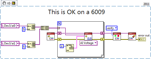
DAQmx C API - maximum number of simultaneous input available channels.
I develop software to purchase customized using the C/C++ API. I have no particular problem with implementing the sample clock, tampons, modes etc. But I have a problem with determination one of the properties of a device:
What is the maximum number of supported Ia-sampled tracks simultaneously (in a task) for a particular device...
I managed to read all other properties (maxrate, physical, ranges channels, Terminal configurations...), but the mentioned property is not found in the API reference. This is related to the error -200168: "number of acquisition channels exceeds the maximum of the device. Well order is not for this, I need the "maximum of device", MAX points out as 'maximum number of channels allowed:» Is this hardcoded in MAX property and must be known for each device, or is there a corresponding value in the DAQmx API? Also if this is the case, where in the documentation and/or specifications of each device is it said?
If it's interesting - I use for most devices M-series (USB6211, USB6009, USB6212...).
Thanks in advance. I will be grateful for all comments and suggestions.
ttaneff is a kind of corner cases where you have multiple copies of the same physical channel in your task. It is sometimes useful for various reasons (for example to be able to enjoy the same channel with a different terminal configuraiton or with another range of entry, or maybe something like this).
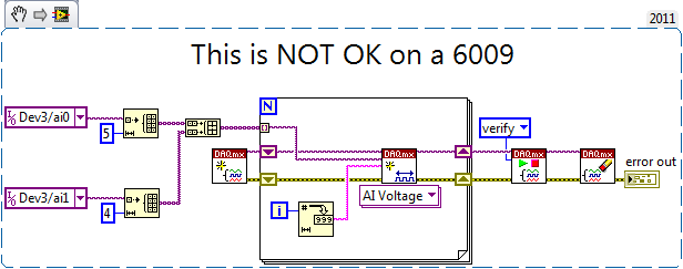
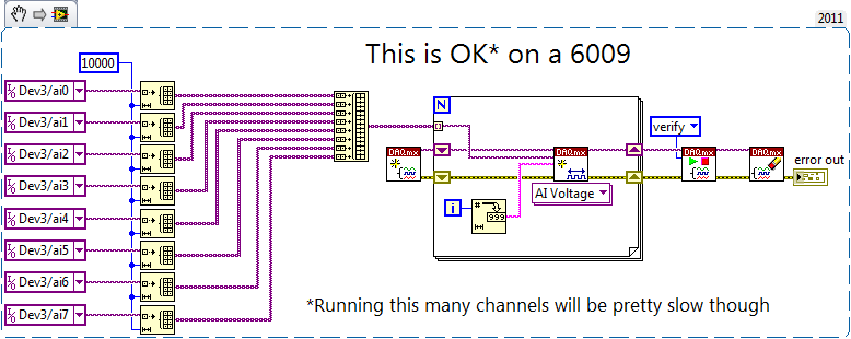
Fast experience, the M Series devices can have up to 4095 channels. The 6009 can have up to 8. There is no property node that refers to these values, and I'm not even not aware of any documentation with respect to them.
However, you can have more channels configured (on each device) if all of the following characteristics apply:
1. you have sets of channels with a similar configuration (physical channel, range, terminal configuraiton all identical)
2. these strings are grouped consecutively to the task (e.g., chA, chA, chA, chB, chB, chB,...)
3. the number of channels in each group of consecutive channels is the same (I'm not sure of the limit of the maximum size of the groups - memory and performance problems are probably your factor limiting)
4. the number of groupings is limited to the numbers above (4095 M series, 8 for 6009).Here are some examples:
EDIT: I just realized that you are using the C API, apologies for examples of LabVIEW - I hope that the examples always wise.
Best regards
-
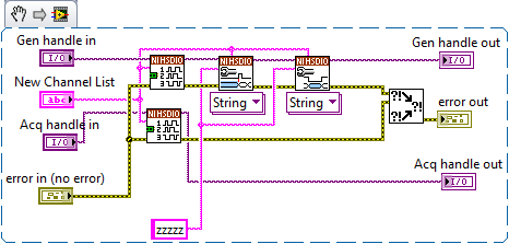
Dynamically change the Ni HSDIO channels
I am currently using a PXI-6552 module to generate and acquire I2C signals simultaneously. I would like to know if it is possible (and how I would go to this topic) to dynamic change channels. My goal is just to pass the two references of NOR-HSDIO (purple variables) to a new slot - VI that I create from a different set of 5 channels 5 channels. For example:
Pseudocode:
PXI sessions initialize;
for (i = 0; i< 10;="">
{
Set the channels 0-5;
Generate and acquire;
Stop the acquisition;
Set channels to 6-10;
Generate and acquire;
Stop the acquisition;
Set channels to 11-15;
Generate and acquire;
Stop the acquisition;
}
close the sessions of PXI;
Basically, I need the fastest way for acquisition channels without having to initialize and close sessions each time.
I am currently using the HWC downloaded the example .zip from here: http://www.ni.com/example/31200/en/. (I've also attached the two that are necessary for my problem).
Init HWC Device.vi: (also attached)
Performance Device.vi HWC: (also attached)
I may need on the screws are Assign dynamic channels, Configure Idle State and initial configuration. However, I don't know if those are the only ones. If it's possible, can I close the original channels and then assign more? Or re-call "Dynamic Assign Channels" automatically disables all channels not assigned? Etc.
The important things to note: I'll put 5 channels at once - for both acquisition AND generation. I need to close the channels and proceed with 5 different channels - for both acquisition AND generation. All channels must be on the State of the 'z' to high impedance permanently.
If you need further information, please let me know! Thanks in advance for any suggestions and assistance.
By trial and error, I was able to find a way to do this:
-
Executable doesn't detect data acquisition
Hello LabVIEW community,
I created an executable file to run on a computer that has no LabVIEW. I installed the hardware drivers on this computer (my DAQ hardware is "installed and ready to use" and detected by the computer on the plug-in). The problem is that when I run the file .exe, all my channels DAQ read just 0. The code behaves as if data acquisition is not connected or is not recognized.
I tried the same executable on the computer where the .exe is created, and the signals are well displayed.
Is there something special that needs to be made during the creation of executables, to ensure data acquisition channels are detected on all computers? It is perhaps a matter of configuration by computer?
Thank you in advance for your help!
If you use DAQmx tasks or channels defined in MAX, then you must export your configuration of MAX to the target computer as well. Your Installer can be put in place to manage the import of MAX settings during installation on the target computer.
You should also follow the advice of crows and make sure that you implement the error handling.
Maybe you are looking for
-
Windows error 1073 usually stop or restart
I try to retrieve or check ererors... But seems that nothing works... I'm trying to quit and I can't because windows will not tiurn off or not restat. I have XP profesional a laptopcompaq tc 4400 and norton antivirus. http://social.answers.Microsoft.
-
How can I recover my product key?
I want to reformat my laptop. But the product key on a laptop sticker partially erased.When I run the Magical Jelly Bean Keyfinder software product key showed me different.How can I recover my product key?
-
ASA 5500 x IPS license to the license of firepower
I recently attended a webcast Cisco and told me that it is possible to obtain a free migration since the IPS license inherited the firepower license if you have a 5500 Series x ASA. Nobody is able to successfully get the free conversion?
-
I want to consolidate my Microsoft email afcounts to make it easier to manage. I have an e-mail address using MSN.com and another under Hotmail.com. Is an advanced features/used more than the other? What is the difference between the two? What is the
-
ISE 1.2.0.899 and large number of alerts
Hey,. I've been in contact with our partner Cisco on this subject, but I do not have anywhere and dismissed the case without a resolution... It turns out that you can not disable alerts are more than 1,000 at a time in ISE. It is a huge problem for m