Synchronization of data from different sample of data acquisition rate
I use a high RT 8135. I'm sampling of signals from analog pressure thermocouples to 20 ms and 10 ms. I use the stream network to transfer the data from the SMU on my host. I would like to be able to synchronize the timestamps of all data to the 1ms sampling note and record in a file.
Search in the file my sampling data 10ms end timestamp does not match the timestamp of 20ms, missing data... I know you have empty queues to get the rest data but is possible to interpolate any data to adapt a unique timestamp?
Thank you!
Hi aokada09,
Looks like you are facing problems resulting from parallel execution two loops you have. There is nothing necessarily bind the two loops together, so that each of them an iteration at the rates you specified, but are allowed to start each software (sort of random) dictates that they start.
To get a solid synchronization, share a sample between the two measures clock, but run the sample clock at 100 Hz for 50 Hz for thermocouple measurement and pressure measurement. You should be able to use shared inside the SMU chassis backplane clock. This will be as close as possible to synchronize without using a card of timing. The only real source of delay/tilt between readings at this point is the physical distance that must travel the clock signal. This will not lead to steep, but there will certainly be some (probably on the scale of the high-nanoseconds or microseconds bass). This article gives more information about the synchronization and the sample clock:
http://www.NI.com/white-paper/11369/en/
Tags: NI Hardware
Similar Questions
-
Hello:
I'm very new to LabView, so I need help to find an idea that can help me to record data continuously in real time. I don't want the file is too big, so I would like a new file in Crete in each 32 mega bytes and clear the previous buffer. Now I have this code can save data of voltage in the TDMS files and the sampling frequency is 2 m Hz, so the amount of data very fast increase and my computer have more ram 2 G, then the computer hangs after 10 seconds, I'm starting to collect data. I need some advice you briliant people.
Thank you very much I appreciate really.
I'm a big supporter of the architecture of producer/consumer . But this is the place that I recommend. The DAQmx Configure Logging does all that for you!
Note: You will want to use a table instead of a graph here.

-
Synchronization of data acquisition
Hallo,
I have four sensors, two encoders, a torque sensor and a sensor of kraft. How can I use the DAQ itsself clock to synchronize the measurement signal? I want to get the signal every 1 milliseconds
Better compliance
Hello TUDarmstadtLLX
downsaved by 2014
-
producer-consumer: optimize data acquisition rates
I have a type of producer-consumer of application in which a single loop continuous waiting there and reads data from the card and another loop readings/backups of data. But besides a loop more trace data. The number of channels and real-time scanning is set by the user, the time it would take to save, view, and analyze each data block (an iteration of analog-to-digital reading) may vary according to different parameters.
I'm putting 'number of samples to get' big enough on analog/digital playback to the beginning so I don't get the overflow of queue. Now I would like to adjust automatically when the program is running so I understand any overflow from the queue and at the same time the data are not exposed in the huge chunks at a time. Someone did he do this kind of thing before? For now, the only idea I have is to read the number of items in the queue at all times and use a mathematical formula to increase or decrease the number of samples.
Abdel2,
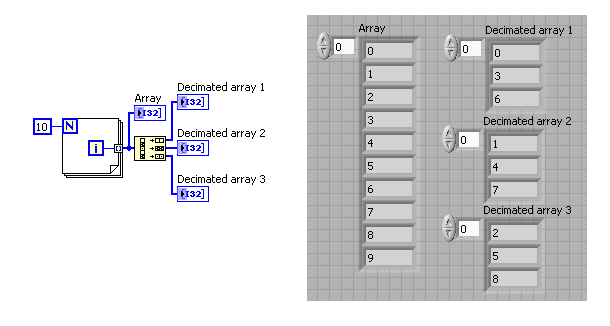
The number of items in the queue of streaming and using a mathematical formula to increase or decrease the number of samples is a good method. You can also use the decimate 1 D table function to display a smaller grouping your data if your problem is that you do not want to display huge chunks of data at the time.
-
acquisition of data with different sampling rates high
I have a few questions on the use of the OMB-DAQ-3005 with different sampling rates high.
For our application, we have 8 analog inputs. Which two are a quick response and should be sampled frequently. We have an encoder quadrature (CPR 1000 running at 1800 rpm). We plan to sample X 4 encoder. For the analog inputs for the quick response, we want to trigger a sample of each pulse or each a few pulses, thus creating a timestamp with the position of the encoder with respect to position index as well as two fast analog inputs. We have data correlating the analog inputs with the position of the encoder. Other analog inputs, we want to measure relatively slowly (for example once every 5 dry or similar).
How can I go on the configuration of the two (or more) sampling rates different wherein I can taste entered at different frequencies? Also, is there a way to reset the encoder count after outbreak of the index as I have the position of the encoder with respect to the index?
Maybe you'll find someone here who uses the OMB-DAQ-3005, but this forum is really more designed for LabVIEW programming issues.
I've never used the OMB-DAQ-3005, but out of curiosity, I took a glance at the Manual of OMB-DAQ-3005. The answer to both your questions are:
1. you cannot run a hardware DQA Multiplex (like this one) at independent rates by channel.
2. the OMB-DAQ-3005 supports an Index Z feature to reset the counter - look for documentation on how to configure any software interface you are using. If you get stuck, you can try to discover media appropriate for instrument channel.
Best regards
-
Import data from different DBs to HFM Application using FDQM
Hi gurus
1. how to import data from different databases to HFM Application using FDQM?
Do we need to write scripts for integration in FDQM, or is there an alternative method, we need to do?
concerning
DevData import is long to explain,
To be more precise,
1. you would establish a connection with your source systems and destination where you pull the data.
You can do this by registering adapters of integration for send_break_action source machines
2. you would then upward some formats for importing, maps and tables of control.
Please go through the Administrator's guide,One of the experts will help you better understand.
Kind regards
David Martin
-
How can I use notifications to send data from different sources for the same chart?
Hello
I use the model of 'Continuous measurement and logging' project comes with LV 2013.
It is extremenly helpful in understanding the messaging between the acquisition, graphic and loops of newspaper. (Thank you NEITHER!)
I ran into a snag though.
I want to change so that my graphic loop receives notifications of data from two sources of acquisition by the declarant.
I have trouble getting the data from the two sources to display on one graph.
I've isolated the problem in the attached vi.
Here's what happens:
1. I create 2 parallel loops data and send the data to a third parallel loop with the notifiers.
2. the third loop receives data from one of the loops because one of the authors of just receiving notifications is to expire instead of receive data.
Can anyone suggest how can I fix?
Thank you.
-Matt
Here's my modification of your VI. I put notes on the block diagram to explain the changes. He uses a queue for data transfer to avoid data loss. It uses a notifier to stop loops. All local variables and value property nodes have been eliminated.
The way loops are arrested probably let some data in the queue. No more of one or two iterations of each of the loops of data acquisition. If you need ensure that all data has been displayed (or recorded in a real application), then you must stop acquiring loop first and read the queue until you know it's empty and both other loops stopped. Then stop the render loop and release the queue and the notifier.
Lynn
-
Buffer the output AO, refresh rate is different from the sample clock frequency
Hello
I am an AO output in the buffer using a single channel. I have a stamp with a ripple of 200000 points with a triangular waves of a 1000pts each repeated 200 times. If I want a frequency of 1 Hz, I simply update this waveform 1000pts and if I wanted to 5 Hz, then 5000pts and so on. But there is some frequency that I won't be able to use like the refresh rate (the number of samples that I ask to update) is different from the sample clock frequency, which makes synchronization with the other difficult to trigger (incomplete cycle). Frequency 3 Hz (update 3000pts), as (update 7000pts) 7, 6 Hz (update 6000pts), 9 (update 9000pts)... 11Hz at 15 Hz and is not valid in the sense that the refresh rate is different from the sample clock frequency. That makes a whole lot of inaccessible CONFIGURED! Can someone tell me what determines the banned frequency? Is this something to do with the material?
concerning
One thing you can try is to change the number of samples per cycle. This cannot give the precise frequency accurately, but can reduce the average error.
120 Hz, the error is currently about 400 parts per million (ppm). The accuracy of the time base is 50 ppm, then this error is less than 10 times the inherent error due to the time base.
Consider this configuration: the closest nominal sampling you rate, you can get is 120048 Hz (1000 samples per cycle at 120 Hz). If your buffer contains 1200 samples per cycle, 100 copies of it would produce 1 second of data to 120,048 Hz. But if the buffer contained an average of 1200,48 useful Samper by cycle, you get the exact frequency. Of course getting 0.48 of a sample is delicate. But the kind of feasible. If you use 48 cycles in the 1201 samples per cycle and the cycles of 52 to 1,200 samples per cycle, the total number of samples per second = 120048. Average frequency will be exactly what you want. Instantly, the frequency is slightly higher or lower than the exact value. By an alternation of 1200, 1201, 1200, 1201... 1201, 1200 100 cycles that the Jig is fast. If you group all 1200s whole and all 1201 s frequency hopping may be more sensitive. If this kind of jitter is acceptable depends strongly on what you do with the release.
This technique is used in some systems of frequency synthesizer.
Lynn
-
Excerpts from continuous data acquisition
Hello
I want to make an acquisition of continuous data with a NEITHER-6133 @ 1ms per channel. The data must be stored on hard disk. At the same time, I want to take excerpts from acquisition to calculate different values. The acquisition of the extract must be triggert by an external digital trigger. Are there examples, which combine continuous data collection and collection excerpts?
Thank you very much.
Best regards
Michael
System
Windows 7
LabVIEW 2012
NOR-6133
Thanks to the support of NOR-Germany, I found a solution for me:
1.) continuous trigger switch
Connect 2) the trigger for the signal to a digital i/o
3.) synchronize AI and DIO
Excerpt 4.) the samples needed by the search within the digital waveform pattern
Result:
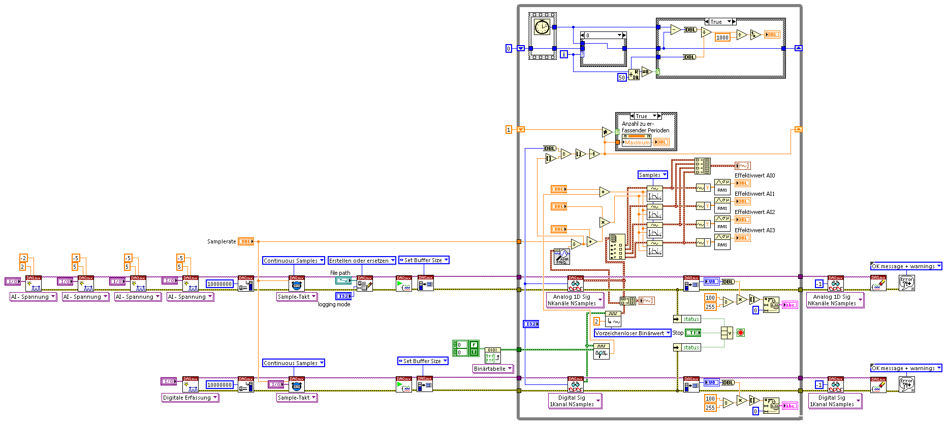
The example shows 4 IA channels Cup (tested on Win7, NI PCI-6115, 4 channels each 5. MECH / s) and calculation on extracts from each channel signal triggered parts.
-
synchronize two loops for written tdms data acquisitions
Hello
I have two loops of different data acquisition. A slow acquisition of CAN (10 s/s) and an analog acquisition faster (30 samples taken at a frequency of 300 Hz), I need to synchronize these data for tdms writes for later analysis in DIAdem.
My example and the result in the DIAdem channel list is attached.
Thanks in advance!
Magnus
Magnus,
for a professional solution, you do not want to synchronize the devices on a hardware level. Since the material CAN work differently to 'traditional' DAQ devices, there are important things to take care of.
Please look in the viewfinder to LV example for the word "CAN". For example, you can choose the example 'several cards CAN and DAQmx map Wfm Input'.
Norbert
-
Card FPGA and data acquisition synchronization
Hi, we are control and data acquisition of several hardware devices (including Photodetectors and translational stages). Until last week, we used all the controls and acquisition using a PCIe-7852R FPGA board. However, we decided to move the acquisition part to a PCIe 6363 DAQ card to improve the sharpness of the tension. During the test, I found that the internal clocks in the FPGA and the DAQ cards are slightly inconsistent (not just a phase delay, but a difference in the period).
I know because I have generated a square wave (period = 20) using the FPGA and gains using the data acquisition card (at a rate of 200 kHz, that is, 1 taste every 5). I have observed acquired place shifts 5 every 5 seconds approximately. Such a change does not occur if the production and acquisition is done using the same Board. Therefore, the only explanation is that the data acquisition and FPGA cards clock frequencies are different. According to my calculations, the percentage difference between their time clock must be 5/5 s = 0.0001%.
Therefore, I wonder if there is anyway to synchronize clocks between them. Or, is it possible that I can drive the FPGA clock-based DAQ hardware, or vice versa? Also, please let me know if there is something trivial as I fix.
Thank you very much.
Kind regards
Varun
Hi Varun,
my post was only one solution...
Your data acquisition card may take an entry to control sampling of trigger. In this mode, samples draw on a rising edge of the external clock signal. As long as you stay within the limits of the DAQ (100 MHz for your card) material sampling works perfectly. There are even examples coming with LabVIEW explaining how to program your data acquisition card...
This mode use you your FPGA as clock source sampling for data acquisition. Both will run on the FPGA clock in sync. When the FPGA is a bit out of 40 MHz, so it won't matter because both devices are triggered on the same clock signal...
-
In data acquisition, I use a loop to query the data from the hardware, another loop to receive the data from query sent by queue loop.
Each time the size of the transferred data matrix is perhaps not the same, so the system can assign different table size and recycle frequently.
It cost memory leak. Or it will slow down the performance, given that the size of the array is not fixed, so everytime need to create a new array of size.
Any suggestion or the best method.
If I understand your description, your DAQ loop acquires data with the parameter of the function of reading-'1 ' for reading at the DAQmx samples. This translates into different picture sizes.
Passage of these tables directly to a queue is valid and she didn't mind important in performance (at least AFAIK) and it certainly does not leak memory.
So the question is more or less:
It is valid that the consumer receives sizes different picture for analysis? How your consumer manages these tables?
hope this helps,
Norbert
-
How to synchronize the data of nike nike + ipod nano 7G
Hello
I use my ipod nano7 for 3 years, but I've never synced nike application data.
But I started to run. I want to synchronize the data in my profile nike +.
I get no pop up in itunes application if I want to synchronize data from nike.Help, please.
Thank you
Check on the screen of the iPod settings in iTunes... Select iPod in iTunes (click on his horizontal bar device button to display the screen of the iPod settings. The side left (in the sidebar), under settings, you see Nike + iPod? If you do, click it. Do you see a framework for initiating sends it data Nike +? Mine is already set up (with my 5th generation iPod nano), so I don't know what it looked like before.
-
Slow response from the user interface with acquisition of data of type long time
Hi all
I have a question to ask more out of curiosity than necessity right now. I've built a program that acquires data from the accelerometer and the Treaty in a number of ways: filtering, FFT, FRFS, things like that, but the answer of the UI is still slow, because I need a resolution of frequency of 0.2 Hz for my data domain, which means that the sample acquisition time is 5s and all this awaits before execution.
My question is this: is there a way to completely isolate the user interface of data acquisition so that it responds immediately?
I tried a design model of producer consumer with queues, but found everything to be always waiting for samples to be taken. Maybe it was exactly as I did.
Thank you
Phil
If you need to sample for 5 seconds in order to have enough data to analyze, so unless you can "predict the future" and "knowing" the five seconds of data, simply wait for the data that arrives. Using parallel loops of producer-consumer will allow data acquisition to proceed (for the next 5 seconds of data) while you do the analysis, but you still have to wait for the data to be analyzed.
Note that the previous paragraph assumes you are collecting data in 5 seconds 'chunks' and analyze each "chunk" (independent) on arrival. You could also do something like having a "second 5 sliding window" which moves, say, a second at a time, giving your FFT a finer resolution of 'time' (at the expense of their independence). This would be a (slight) change in your loop of producer (you want to taste in 1 second pieces, accumulate 5 these pieces) and the consumption loop (start analyzing, spewing a FFT every second, while replacing the older "chunk" with the most recent - a queue with loss can do for you).
Bob Schor
-
2 channels of AI on a data acquisition with the range of different sensitivity
This vi is based on the 'new project' state machine on the home screen at the start of LV.
A time loop is parallel to the main loop of the state machine, shown in the picture.
It works continuously until you press the Exit button.
The problem seems to be in start this... > read >... stop start > read >... stop along the error line.
The reason for this clumsy arrangement power is measured voltages are in two lines of different sensitivity.
The shunt voltage is small and needs-. 2 to the range of V.2. The load voltage is greater and 09:50 V range is good.
In the initializing state, two separate vi 'create a channel' have been used to specify the range of voltage to the physical channel. The corresponding tasks are sent via via local variables.
DAQmx errors happen randomly, sometimes the first iteration, sometimes the 50th.
I tried to disable one or the other start > read > stop for the shunt voltage or load.
I tried replacing them with the DAQ assistant.
I tried various DAQmx vi: "wait" and "accomplishment of the tasks by resource cancel selected".
But error-50103 "specify resource is reserved" keeps popping up.
Is it possible to create two tasks on the device even when they are not used at the same time?
The only reason is to measure in two voltage ranges.
Win 7 Pro 64-bit
2014 LV database
Data acquisition equipment: USB-6210
Thank you.
This has been discussed many times. Do NOT use separate tasks. You can use different ranges for different channels with a single task. Just wire the task from one channel to another channel to create task.
You also use local variables when they are certainly not needed.
Maybe you are looking for
-
I have re-installed fireforx and now my sync will not work
I have re-installed firefox on my computer, and now used to sync my ipod to the top. I log on my ipod and now I can't go back. I would like to cancel the ACCT of sync., so I can start again. How do I do that Thank you, [email protected]
-
Qosmio F50 - 126 - Nvidia card is not displayed in Device Manager
So, I have recently installed Windows 8.1 and fully updated. But no matter how many times I uninstall "Microsoft base Display Adapter", windows is not DETECTING my card to install the appropriate driver. Back in the day when I installed first windows
-
Problem Windows xp file association
Hello I installed Wise Registry Cleaner thinking that this would make my fast computer but instead, it made my computer opens is not .exe and .bat files. If you need a my computer specs just ask. (Note that I can't list them all not because I can't o
-
Screen with Z2 problem is no longer automatically rotate
Had this phone less than 2 weeks, auto rotation worked well. It will not work with any of the features on the phone now, same with lit. Tried an app on the app store, it works very well. Someone from Sony will give me an answer? Thank you
-
I received a call from someone who said they were working on behalf of Microsoft operating systems, they told me they had my error reports and that the operating system is currently infected. I needed to put an address to go to the technical support