Synchronize the analog continuous entry and continuous analog output using the unique PCI6024E data acquisition card
Hello
I want to generate the continuous signal and at the same time I want to read that signal that I generate using a single card DAQ. I want to generate signal and the received signal is synchronized and in phase.
I looked at several samples on the sync, but it quiet confusing. One using the same clock of entry while the other use a trigger to start. I use the PCI-6024E DAQ card.
Can someone help me in this regard?
In two of these screenshots, the task to HAVE started first (that's what you want, because it is the task of the slave).
Typically for AO, you can simply write a unique period of your waveform, and then regenerate again and again. Your waveform would be preset before the task starts. If you need to update the waveform on the fly according to enter programming during execution of the task, you would disable the regeneration. In addition, if the wave form is such that it cannot be easily represented by a predefined buffer (for example, it is a strange frequency which is not a same ditch at the bottom of the sample clock), then non-regeneration is the way to go.
Best regards
Tags: NI Hardware
Similar Questions
-
the relay control data acquisition
I am creating a vi that controls (press and release) several relay using a USB 6501 data acquisition. This should be a task relativily easy but I get flumoxed by errors. I tried to use the examples, but I get an error telling me that I need to use the mode of generation 1 sample (on request). Help, please
Sure. The easiest way is to have a DAQmx writing followed by a function of delay, followed by another entry, followed by another period. Simply plug the error links in order to control the flow of data. However, the VI would be insensitive so you can use a state machine or function elapsed time so that the VI can be stopped without waiting for waiting for him at the end.
-
I am building a system and I need to help experts to choose the data acquisition card.
Hello world
I am currently working on a design project I need to take a data acquisition card that responds to the output of the amplifier. I'll build a force detection system which I have taken the following as detector and amplifier:
http://content.Honeywell.com/sensing/Sensotec/pdf_catalog08/008834-1-EN_Model_UV%20Bridge.PDF
http://content.Honeywell.com/sensing/Sensotec/pdf_catalog08/008638-1-EN_Model_53.PDF
Please recommend me which data acquisition card I could take. The only requirement I ask is to have less than 0.1% global uncertainty.
Thanks for anyone who can help
Since your amp has - 3db at 7 kHz and you need only 10 bits 0.1% will do almost any card with. USB-6009 is the lower end. USB-6210 the next step.
Then take a look at some other boundary conditions: do you need it calibrated? (Is there a QM adj. who could ask questions?) Space?, EMC/noise, entry, differential
Take a look at the USB-9237 with a conditioner bridge construction...
-
How to find the time between two channels of entry in the data acquisition card or pci 6036
Hello
I read a lot-related posts on the simultaneous measurement of two input voltage of similar channels in map data acquisition. I know that the best material is "simultaneous measurments of the Series DAQ cards" but I only pci data acquisition card 6036 and I try to understand what is the time between the reading of the two channels . This period is always constant? (must it rely on a voltage (amplitude, frequency, waveform..). I send the sine wave (s) to the two channels and read the values of V, if they read the same value, the difference should always be zero but I get-0,002 to 0.002 Volt difference (I must find a way to convert it in time). A screenshot of my VI is attached. I wonder how I can accurately measure the time delay between the channel.
I am open to any suggestion, my final goal to read exactly two channels at the same time ((ou connaître le délai exact donc je peux correspondre les données correspondantes étant donné le temps de retard))
Hi spinup,
better you should post your question in the forum of LabVIEW, LabWindows/CVI is used

Good luck.
-
How to increase the speed of data acquisition?
Hey, currently I using 6210 OR of data acquisition and control switch. I used labview to periodically check the 7 switches and read data from 7 channels in the meantime (1 sample on request). I ran 70 loops for 10 groups of data, the cost of the time looked like 2.2 seconds.
I would like to end a 700 loops in 2 seconds, is it possible to improve?
Thank you
PEM
Look at the Terminal stop of the DAQ Assistant Express VI. You are starting and stopping of the task for the acquisition of data on each iteration of the loop.
Starting from the help file:
Stop
Specifies to stop the task and release device resources when this Express VI ends execution. For ongoing tasks, this entry is FALSE by default, which means that the task is running until the application terminates. To stop the task, you can use the device again in the same application, wire control wire you the Conditional stop this entry to the same terminal of the while loop. For single-point and finished tasks, this entry is TRUE by default, which means work stoppages after all samples are acquired. To optimize the performance of single point when using this Express VI into a loop, wire control wire you the Conditional stop this entry to the same terminal of the while loop.
Also from the help file:
Continuous single point of entry or exit, the of VI Express DAQ Assistant cannot allow optimal operation. See Acq & chart voltage-Single Point optimization VI in examples\DAQmx\Analog In\Measure Voltage.llb for an example of techniques to create more powerful applications, single point of I/O.
-
Hello
Need driver for PCI and Signal Processing controller HP 240 G4-328TX Data Acquisition
Can anyone provide me please the link for download it for windows 10
Thank you
Hello:
See if this driver works...
-
How can I pause and resume the analog output using DAQmx?
I use a DAQ hardware to produce an analog waveform. I would like simply to break the output of the wave and then resume where it left off. I use DAQmx and LabVIEW 2011.
I've seen examples that use a digital or analog break trigger, but I would take a break in the software only. How can I do this?
-Joe
Hi Joe!
I spent some time thinking about it and I realized that you can technically use a fundamental mission of the analog output, as you previously wrote that runs continuously. However, the generated output samples are controlled by the sample clock pulses, and can be manipulated to fit our needs "suspension."
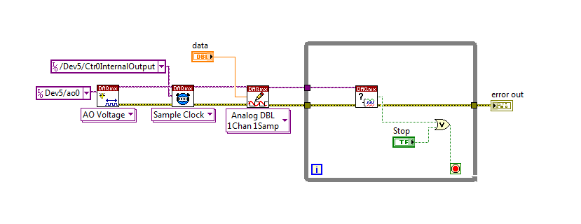
To do this, we will need another counter task that generates a pulse train (see our examples of shipping under material input and output > DAQmx > generating digital pulses > generate dig Pulse Train - Continuous.vi) that stops and starts the user to choose. This can be in another quite VI or controlled by software. We will use this as the task of our output sample clock.
Then, the task of the AO, wire a constant to the sample clock source and select ' DevX/CtrXInternalOutput"based on the counter that you specified in the task of counter. You will need to choose "I/o name of filtration" and check the box that says "include advanced terminals' and right-click of the constant. See picture attached as a reference. In this way, the task of the AO is constantly running, but it generates only actually all data when the meter running task.
Let me know if you have any questions!
Have a great day!
-
Synchronize the clocks of 2 PCI cards for analog inputs with e/s digital reference
I'm trying to synchronize the clocks of reference of 2 PCI cards so that the analog inputs are synchronized. However, my appilcation has also digtial e/s on two cards, and who apparently made the mistake DAQmxErrorResourcesInUseForRoute_Routing. This discussion describes a similar problem, but the solution was to just put the reference clock to the slave device, who had no other tasks running on it, so what mine does.
Is there way I can synchronize the clocks of refernce without interfering with the digital I/o?
Thank you!
PS: My application is in C++.
The reference clock is really a lower-level component that is shared by all resources on a given device. All tasks on a given device must use the same reference clock. So if you use DAQmxSetRefClkSrc for a task, you can use it to set the same value for your other tasks.
Best regards
-
Analog output using DAQmx task
I need a signal to analog waveform using 6259 output, I followed the instructions to "Build an analogue output VI in NOR-DAQmx" in the developer area OR, when I run the code I receive thefollowing error message
"Error-50103 occurred in the DAQmx write (analog 1-d Wfm NChan NSamp) .vi:3.
Possible reasons:
The specified resource is reserved. The operation could not be performed as indicated.
Task name: _unnamedTask<1A> '
and when I press "continue" it goes ahead and track waveform on the front panel, but do not display it on the test panel in max could someone suggest how I might solve the problem?
Hello
Could you try the attached VI and let me know if it works?
I noticed that you receive information of the waveform sample clock, but the type of dynamic data that you use has no data of time in it!
-
Analog output using waveform Timing stops in brief
This is a pretty abstract to describe problem, so I'll try my best.
I give myself two entrances, a low and a high. Here are the tensions. I create a signal which will be the ramp from low to high and from high to low, forming a pyramid. The signal that I create is perfect. The dt signal.001 because I'm out there at 1000 Hz in an analog channel. I left it to an analog of the ExpressVI using "Waveform Timing" (the little box with a timer on this issue when the information of sampling). The problem is when I change the number of samples with this signal. It seems if I increase the examples of this signal (dt-keeping and frequency of output, thus increasing the LENGTH of the signal), the Express Vi that emits the singal stops and does not address the rest of the signal.
I can't rip off code to post here because it is not my property. I hope someone has an experience with this and can explain how an Express VI would cease treatment of an intermediate signal of the signal.
Thank you
I have corrected this problem.
If you are using an express VI, the FIRST time you call this VI, all timing information you pass, the VI will be remembered forever and he will never change. I had to replace by the low level screw and stop/clear the task in order to erase this memory.
-
Synchronize the dictionary of data with model only works for models imported?
When I imported data dictionary model (file-> import-> data dictionary) then in relational model the two buttons "Synchronize Data with Model Dictionary" and "Synchronize model with Data Dictionary" works very well.
But when I model created from scratch and I'm clicking on the buttons "Synchronize data dictionary with the model" or "Synchronize model with Data Dictionary" nothing happens.
It works only for models imported?
(Data model EA 3.3)Hello
Yes, Synchronize only works for objects that were imported to the original (like Synchronize uses the information entered during the import to determine which database connection and the database object to compare to).
If your model is not imported, you can achieve the same effect as follows:
-Open the template in Data Modeler and also open the relevant physical model.
-Do an Import of data dictionary, select the objects you want to compare with that.After the import phase, this will display the dialog box to compare, showing the differences between the objects imported from the database and your model.
Note that if you intend to generate the DDL to update your database of the difference (as in "synchronize with Model Data Dictionary"), you must select the "Swap Target Model" option in step 2 (select database schema) data dictionary import wizard.
David
-
BNC-2110, 6023E PCI card and Labview V9.0: sensitivity of data acquisition (change more little detectable voltage) is 0.002V
Hi, I use the software/hardware above to read a voltage of a potentiostat world Precision Instruments No..
I'm trying to record changes in voltage as low as 0.0003V but using the wizard DAQ, I seem to be limited to a sensitivity of 0.002V. This is the limit of real sensitivity or have I missed something?
Any help would be greatly appreciated.
Hi DCAM77,
Thanks for joining the forums!

The PCI or 6023E has a 12-bit ADC. In other words, it can make the difference between 4096 (2 ^ 12) different levels within the range of cards. The card you have has a selectable range by ± 10 V, ± 5 V, ± 500 mV or ±50 mV software.
This means that the minimum detectable variation will be 4 mV, 20 mV, 244 µV or 24, depending on the chosen range µV.
You should be able to use the ± 500 mV or ±50 mV to get the least significant bit (LSB) value, you need, even if it means that your signal is located between these values. If not, then you need to consider other materials to the application, or the addition of external circuits across the signal.
-
The reading of data acquisition via tcp
Hello
I am building an application that controls an acquisition of data via tcp.
I have a JAVA program that communicate with labview, give a command and data acquisition starts. (So, I read the correct Java data at Labview)
My problem is if I try to read data acquired by data acquisition (continuous sample 1 k samples), I've read strange values.
I transform of double values in the string and send it via tcp.
How can I read it in Java? What type of socket should I use? What is a rate problem?
I also tried to transform small/big-endian byte order, but it does not work.I enclose a sketch of this part of the application.
Please help me, I try for 2 weeks!
Thank you all...I find the solution in the lavag forum.
I post here, if it can help someone.http://lavag.org/topic/16359-sending-LabVIEW-data-via-TCP/page__pid__99983#entry99983
-
Configuration of the two of the same model data acquisition
Hello, community of NOR.
I'm an intern in mechanical engineering with experience in base with LabVIEW.
I would like to speak to OR directly on this issue, but I don't have a service contract and my company wants me to understand this before you buy LabVIEW.
I hope that someone has experience about my question, and I would be very happy to help.
We intend on purchasing an expansion card for our acquisition of data (OMB-USB-2416), but unfortunately it is offline and no custom would not happen in time.
So, I need LabVIEW to read voltage HAVE two of the same model of data acquisition, which would amount to about 30 channels.
Is this possible with LabVIEW?
Thank you.
Measurement computing says that the "physical channels" dropdown list is automatically filled in once both devices are configured.
-
Information about the properties of data acquisition
Hello
I'm William, a student from Belgium (technical measure and control). For my thesis in June, I need to make a comparison between the USB 6008/6008 and myDAQ device. I must do this based on the specifications of the devices. Specifications of several I found in the manuals are very interesting, but I don't know what they mean. Can someone explain it to me as 'temporal resolution', the 'input and output resolution' and the 'steering control. Are there simple experiments with Labview to show the difference of several between two DAQ devices?
with friendships.
William
Hello William,.
I don't directly know specific tests about the comparison of the time resolution for these cards.
Of course, you are always free to do these tests yourself and share them with us.
Maybe you are looking for
-
Recently, I moved a large number of emails (filtered by sender) in a new folder I created in Thunderbird.The emails themselves arranged in threads that are independent of any discernible factor. Some e-mails with 7 years in dfference are strung toget
-
Satellite C660D-101-PSC0UE-00Q017GE - need to monitor cable
I'm looking for the cable of the monitor for this laptop. Anyone know how to find the model of the cable without having to open the laptop?
-
Pavilion p6-2100 processor upgrade compatibility
I am trying to upgrade my HP Pavilion p6-2100, here are the features of HP on my desk: Pavilion p6-2100 What I need to know is the following. The AMD A8 AD3870 series is compatible? Here is a link to the product that I think to buy: AMD A8-series AD3
-
HOWTO estimate of progress during the use of parallelism of the iteration?
If I have a loop with the parallelism of iteration activated, is there a good method for updating a progress bar without eliminating the potential speed boost? The naïve approach to divide the final iteration by the total number of iterations is goi
-
Stop the spooler: type services.msc in the box "Search". And then double-click the label of 'Services' that appears. Or Start->computer and right mouse and then "Manage", click on "Services": Scroll down the list of services down to "print spooler" a