TDMS multiple channels, frequencies of different sampling
I'm developing an application c ++ under Windows 7, which must record the sensor data acquired on the disc. The data consists of approximately 1 500 channels sampled at rates that vary between 100 samples/s and 1 sample/s with data types which could include the floating, whole, decimal point fixed and boolean. We need log on without interruption for hours at a time. In the past, my company has used LabWindows/CVI to write TDMS files for this kind of application, but the number of channels has always been much lower and all channels, we sampled at the same rate. I was instructed to use the LabWindows/CVI/PDM solution for this new effort, but I have concerns about the way in which it will occur in the conditions I described above. My questions:
* It OR application notes dealing with best practices for recording several channels of data sampled at different rates for TDMS with LabWindows/CVI files?
* Are there performance indicators which show the capablities and the limitations of LabWindows/CVI/PDM in conditions similar to those I describe?
* Someone here any experience – positive or negative – with TDMS in a similar application which they can share?
TIA
Hugh
I had an Exchange offline with Technical Support OR on this subject and received the following guidelines, which I consider the Gospel:
You should be able to connect to TDMS in CVI for your strings from 1500 to different rhythms without problem provided that your computer has enough memory. You can set up groups and with 1500 channels you should probably, in the interest of the Organization, but it is not necessary to create groups to limit the number of different sampling frequencies. Alternatively, you can generate different files to separate data, which are also recommended, but not necssary, based on your preference for the organization rather than the need for the maintenance of sampling together in the same file. TDMS supports asynchronous writing, so you should be able to connect different channels at different rates for the same file without errors in access to the files or something like that. One thing, you might encounter is slowing a lot of simultaneous writing. I found this example of community which shows how to write data to disk faster using the advanced TDMS API. Please visit the following link: LabWindows/CVI Tip: write data to the disk faster with TDMS Advanced API https://decibel.ni.com/content/docs/DOC-33401
Tags: NI Software
Similar Questions
-
How to acquire with NiScope at different sampling frequencies and lengths Records?
I need to acquire the data of 2 channels of the NI PXI-5114 map two different sampling frequencies high, at the same time. Also, I put 2 different record length. Is this possible?
I understand that 'Vertical' settings can be configured for individual chains because the function 'Vertical niScope Configure' has 'channels of entry with which we can assign the desired channel. But for horizontal settings such as "min sampling rate" and the record min length, I could not find such an option to specify the channel. Would it not common to both channels?
I hope that the device is capable of simultaneous sampling and therefore channels can be configured individually to different sampling rate.
Hi AJ_CS,
Why do you have to be distinct from sampling frequencies on channels separated from the digitizer even? What different sampling rate do you want?
But for horizontal settings such as "min sampling rate" and the record min length, I could not find such an option to specify the channel. Would it not common to both channels?
You do not have an option to configure the settings of hoirizontal on a channel by channel basis because this concept does not exist in the traditional sense of the use of a scope. Compatible with the concept of IVI, an oscilloscope traditional benchtop will have only a button or a set of buttons for setting the parameters of synchronization of the unit. There is therefore no horizontal configuration to separate channels on the scanners NOR.
I hope that the device is capable of simultaneous sampling and therefore channels can be configured individually to different sampling rate.
Similar to a traditional benchtop oscilloscpe, the device is capable of simultaneous sampling. But as mentioned above, the channels can not be configured for different sampling frequencies high.
However, you can ignore data that you think is not relevant. For example, if you assign 100MS/s CH0 and CH1 to 50 MS/s, then you throw all other samples.
Alternatively, you can use separate scanners (a channel on each digitizer) and configure them to taste at different rates. You can set frequencies of sampling on scanners NOR separated and even synchronize them with TClk.
-Andrew
-
Sampling Multiple channels of unique cDAQ Module
Hi all
I am currently researching the use of cDAQ for a system of analysis of oil, especially the module OR 9201 for voltage GOT.
We have 6 entries SE located in the voltage/current ratings, although they all need different sampling frequencies. It is my understanding that the module is capable of 500 kHz, which will be split between entries.
The sampling frequency should divided equally? Or could I for example send a 250 kHz channel and split the rest between the other 5. Synchronous between devices is not necessary.
Many thanks in advance,
Peter
Peter,
See my replies to each ball:
- Am I correct in saying that I could taste each module to a different sample rate? Yes
- If I taste the 9201 to 500kHz/6ch, will I have an effective sampling frequency of ~ 83kHz on a given channel? Yes
-
DAQmx showing not readings to multiple channels
Hello
I am trying to acquire values of temperature of 3 consecutive using a task DAQmx channel as shown in the attached photo.
I have a loop of producer-consumer for fast reading and writing samples in a file.
To specify the channels, I typed in the box connected to a terminal of "physical channel" (not shown in picture) as follows:-SC1Mod2 / ai2:4. This is to acquire a reading of analog channels 2, 3 and 4. The program must then write a file reading on channel 3.
The code works perfectly if I purchase samples of 1 channel only.
When I try to acquire multiple channels, I don't see readings on one of the task of acquiring Wired Digital indicators.
I would appreciate your input on what might be wrong with the code.
Thank you.
kumv10 wrote:
The broken wire seen in the photo is the result of adding more channels to the task of acquiring. I managed to get around this by specifying a different, but even with an intact wire data type, the program is not displayed readings since the 2 remaining channels.
Instead of use for dynamic data Type, then the channels Split, just use an array of Index to get your three values.
-
Generation of series in multiple channels
Hi forum, I need to ask a few questions. Any help is appreciated.
(1) I need help with the generation dynamic series in several channels. Here, we can see how the dynamic data set generated by a single channel. But I can't find anywhere, how to generate several series signals in multiple channels.
(2) what is the limit for this generation series? I think it depends on the material, but I don't know, what is the limit. My hardware is SMU-6544.
(3) it is possible to generate different signals in different channels using scripts? and to start the production in these channels at the same time? the example given in the script generation labview is unfortunately only for the generation of a channel.
Thanks in advance,
Kind regards
Yan.
Hi Yan,
Produce on several channels with multiple data is difficult without a tool to view the data, or series of each channel bitstream concatenated into a software ADE and transposed before be downloaded into memory. To make Visual things here, I'll assume that you want to generate a pattern of 3 bits on sample of channels 0, 1 and 2 is 8 wide. Assume the following models of the series bit for each channel:
ch 0: 0101 1010
CH 1: 0000 1111
CH 2:0100 1101
So the question now is, how do you load this in the SMU-6544(or any other HSDIO hardware)? Of the two options, you can use Digital Waveform Editor (NEWS) to create visually and save to a file type HWS then load a DJ using the API HSDIO. It is the easiest in my opinion.
The second way is construction examples of data based on a basic example. I want to say is you take it all binary streams and built a 2D table so that it looks like:
01011010
00001111
01001101
An array of 3 x 8 and then transpose the table that turns into:
000
101
000
100
111
011
110
011
Here you can see we have 8 lines, each line is a sample, and in the form of U32 read in decimal, you get 0, 5, 0, 4, 7, 3, 6, 3. That's what you can load into our niHSDIO U32 function write a waveform. I hope you can see how this translation occurs and how it looks like in terms of load on the jury. Each sample usually contains data for all channels, where each bit in the U32 is one of the 32 channels available on your device. So if you want to write a '1' on Channel 5, you would load a value of 0000 0000 0000 0000 0000 0000 0010 0000 in the form of sample, where the 5th bit is 1 and all the other bits 0. In decimal, you would write '32' value.
With regard to the limitation of the size of series, if your flow rate is slow enough you can disseminate and make an almost endless stream, but assuming that you are running at the maximum rate, your series of waveform size is limited by the size of your on-board memory. Since each sample generation is 32-bit, which is 4 bytes for example, if a memory size of 32 MB will correspond to 8MS bitstream series max.
For any questions or comments are welcome. Thank you.
-
acquisition of data with different sampling rates high
I have a few questions on the use of the OMB-DAQ-3005 with different sampling rates high.
For our application, we have 8 analog inputs. Which two are a quick response and should be sampled frequently. We have an encoder quadrature (CPR 1000 running at 1800 rpm). We plan to sample X 4 encoder. For the analog inputs for the quick response, we want to trigger a sample of each pulse or each a few pulses, thus creating a timestamp with the position of the encoder with respect to position index as well as two fast analog inputs. We have data correlating the analog inputs with the position of the encoder. Other analog inputs, we want to measure relatively slowly (for example once every 5 dry or similar).
How can I go on the configuration of the two (or more) sampling rates different wherein I can taste entered at different frequencies? Also, is there a way to reset the encoder count after outbreak of the index as I have the position of the encoder with respect to the index?
Maybe you'll find someone here who uses the OMB-DAQ-3005, but this forum is really more designed for LabVIEW programming issues.
I've never used the OMB-DAQ-3005, but out of curiosity, I took a glance at the Manual of OMB-DAQ-3005. The answer to both your questions are:
1. you cannot run a hardware DQA Multiplex (like this one) at independent rates by channel.
2. the OMB-DAQ-3005 supports an Index Z feature to reset the counter - look for documentation on how to configure any software interface you are using. If you get stuck, you can try to discover media appropriate for instrument channel.
Best regards
-
Hello, I have another problem here, just started to learn the filtering and decided to practice on the job making, im if you have this one question: I have two signals on channels of entry of two pressure sensors that come with high noise. I tried to split the signals, filter, and then merge again to send to waveform, but it does not somehow, and I thought that if there was a specific filter for multiple channels, I read that some TREES can divide signals itself and merge them automatically, but I couldn't find one. suggestions for beginners? Thanks in advance

PS by the way, managed to filter one of the signals manually split and for some reason, the waveform to the display of the data of pressure with sound sensor stops working after apprx 3 sec, it kind of drags a bit and then goes black blank, so any suggestions on this point, would much appreciate
PPS two graphics of waveform showing the initial data of the sensors go blank after a while at the same time black

Hello Pomplamoose,
I forgot to mention something: If you set playback VI to N samples then wire a constant for the number of samples per input channel. A good way would be to read in samples of 1000 per iteration.
Part Fliltering:
First of all, if you want to filter the high sounds you use Lowpass Fliter.
Attached you will find your VI with 2 ways how you can filter your signals.
(1) easy solution with express filter VI.
(2) VI of Butterworth filter, the way in which you the tried.
Some explanations to 2):
If you use the butterworth VI as a low pass/high pass filter filter, it ignores the entrance of high cut-off frequency. The entry, you should use is the lowcutoff FREQ.
In VI I provide you with there is no synchronization of the signal information once it is filtered, because you only use data of Y of the type of waveform. If you have calendar information in your signal you could do that with the construction of a waveform type after you filtered the data Y.
Therefore, you have no synchronization of the signal you need to resize the chart you can see the filtered together signal.
To merge the signals after you their filtered, you have 2 ways:
(1) build an array of filters.
(2) use the signals of fusion VI.
If you need help just ask, otherwise mark as resolved.
Kind regards
Markus Mayr
-
Audition 3 seeing pricing different sample than that the device presents
Hello
I just installed Adobe Audition 3 and 3.01 patch, on a brand new system running under Windows 7 64-bit. The motherboard is an Asus Sabertooth X 58 using Realtek High Definition Audio. Device drivers show that for line input audio sampling rate is set to 24 bit 192K. I wanted to put up the sound card would test the performance and audio quality.
The problem is when I raise Audition 3 and hit record, I get the message 'we don't support recording when your file does not match your hardware sampling rate. Current hardware sample rate is 44100 Hz." Clearly, this isn't the case since the line properties - Advanced tab displays "2 channels, 24-bit, 192000 Hz (Studio quality).
According to the installation of the audio of the hearing, it shows only one choice for Audio Driver: Audition 3.0 Windows Sound. It also displays the sample rate: 44100 Hz, clock Source: internal buffer size: 2048 samples with no way to change these values.
If I click the button on the Control Panel, I get:
DirectSound input ports:
Device name: line (Audio device high definition)
Audio channels: 2
Bits per sample: 16Anyone know how I can change these settings to get the hearing agree with device settings?
Thank you
Dale
DaleChamberlain wrote:
Anyone know how I can change these settings to get the hearing agree with device settings?
I'm afraid that life is nowhere near as simple as that. The main issue here is that hearing, in common with most of the audio software, uses a system of driver called ASIO to speak with the audio device - it will cancel much of the operating system and significantly reduces the latency of the system. There are several problems with ASIO if - the first being that it supports only one device per system (or sometimes multiple devices identical if the manufacturer can make look like a single device) and with software designed to use this driver, then to use any other driver (like a native Windows) you must use a converter like ASIO4ALL step. This convert the ASIO WDM Stream and allow you to use multiple devices sound - but with an increase in latency.
That's the second problem that will really you stuff well - and it's quite reasonable, ASIO is limited by its inventors to run only three sampling frequencies; 44.1 k, k k 48 and 96. So there is no way you can run that you think that may be a higher quality setting. All of the above parameters even 48 k make your audio device much more difficult work and what for? All that happens is to increase the potential bandwidth to well beyond the range of human hearing - to no purpose at all. You do not have sources that can produce useful at these frequencies output, and you certainly do not have the means to reproduce. This all is well documented and explained before, so I'm not all that again. In a Word, Nyquist points out that any device digital sampling has a bandwidth limited to a maximum of half of the sampling frequency, for 48 k which gives us a frequency upward to 24kHz response - comfortably more high that any adult can hear from far away. Whatever it is you enjoy and save out of it using the same 96 k nothing but noise is as far as humans are concerned, and unpercievable of noise to that.
What says the line properties tab is so, if you have a no ASIO driver designed to support all the possible, possible rates. You don't have an ASIO driver is available, because it is a built-in audio device, and anyway you have already pointed out that it uses the Windows driver for the hearing (a lighter version of ASIO4ALL, actually), so a conversion is already underway. Call Realtek as "High Definition Audio" does not exist - all audio devices built of this nature exist to universally of poor quality and improve it that you would need an external device - which are numerous, usually with ASIO drivers dedicated. But none of them works with ASIO beyond 96 k, everything simply because the standard does not support higher rates.
If you download and use ASIO4ALL (it's free), then you will get a control panel extra that will show you exactly what your audio device is able to do as much as hearing or any software ASIO is concerned, it is a useful diagnostic tool anyway, so it is better to do. Simply select this option during installation, instead of hearing Windows driver.
I'm sorry to be the bearer of what appears to be bad news, but in fact, it is not. You won't see any difference in quality at all the clocked at something beyond 48 k sampling frequency; everything you do needlessly wastes the resources of your computer. Waste you the resources processing and disk space available by treatment at ridiculously high sampling rate, and there are zero returns.
-
Dedicated for each channel from multiple channels in a single task task disadvantage
Hello
My current acquisition software (C + c++ / GCC) encapsulates the methods rather clumsy niDAQmx C to interface with the data acquisition equipment in a class that represents a task of acquisition. This way I can create several instances, for example counter input, analog input, analog output, their terminals and the class supports all work low level as ensuring input analog fake internal is started if there are only counter entries such as the sample clock starts, or configure reminders N-sample, etc.
It seems to work very well, and also the time seems to be good, because first of all the tasks on multiple instances of my wrapper. For triggered early, that I use
DAQmxCfgDigEdgeStartTrig(mTask,mTriggerTerminal.toAscii().constData(),DAQmx_Val_Rising)in-house.
Now my real question: what is the advantage of multiple channels, when everything seems to work fine with multiple tasks and only one channel per task? I don't see the disadvantage, it would first classify necessary acquisitions in types (I, ao,...) because several strings in a single task must be of the same type. With my approach I need not care because each channel still gets its own task.
I don't know I'm missing something here. Maybe someone can explain it to me, maybe some limitation of multi-tasking, I have not yet read.
Hey!
Unless you specified for managing the it (simultaneous sampling) or modular instruments and hardware devices (see link )
You cannot perform two tasks at the same time that access to the analog inputs, for example, because the
ADC is a shared resource that is connected to a multiplexer, and that only one task can work in it at a time given. (see here )
Similar restrictions often apply to other types of operations.
I'm not aware of any performance issues, perhaps a little more memory could be used.
So as long as your hardware supports what you are doing, you should be ok, I think,
and it is only a question of clarity and intelligibility, ease of use and structure.
As you use classes, I'm sure you've heard about encapsulation - so it is a
question of how you want to design your application.
In addition, when you work in LabVIEW, tasks feel more natural to the principle of data flow, because you have a thread for your data acquisition,
and it works very well with our modes of standard design.
So, if it is better for you (and works with the hardware), you can give all the channels its own task.
Hopefully this might clarify some things,
Kind regards
Rome
OR Germany
-
Replace negative values in multiple channels with "0'.
Hello
I'm calculating and then by creating a cumulative channel, multiple channels. Negative values in these channels aren't necessary, and I need a nice way to replace each negative value in these channels with a value of '0'.
My current code is:
Do
Do
If Data.Root.ChannelGroups (2). Channels (i). Values (II)< 0="" then="" data.root.channelgroups(2).channels(i).values(ii)="0 ">
II = ii + 1
Loop until the second > Data.Root.ChannelGroups (2). Channels (i). Properties ("length"). Value
II = 1
i = i + 1
Loop until I > Data.Root.ChannelGroups (2). Channels.CountIt works, but I don't like. He adds a few seconds when running my script, which was almost instantly. Is there a better way to do it?
Thank you.
Hello Kevin,
The fastest way to go through a channel and check the values less than or equal to 0 is through the canal's calculator. The code below takes all the channel first channel group (with the exception of the first string that is be the weather channel in my example data set) and replaces the values<0 with="" 0="" through="" the="" iif="">
Set Group = Data.Root.ChannelGroups (1)

iMax = Group.Channels.Count

FOR i = 2 to iMax

  Adjust the strings = Group.Channels (i)

  Formula = "= IIF (y '.<0, 0,="">

  Call to calculate (formula, Array("y"), Array (Channel))

NEXT ' I
In this example we overwrite the existing values of data channel with 0, but you can also copy the channels to make sure that your raw data is available.
The calculator of channel is extremely fast for this type of operation because it does not create a loop to go if each line separately and check the values he...
I hope this is useful,
Otmar
-
Trigger multiple channels of PFI
Hello world!
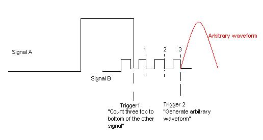
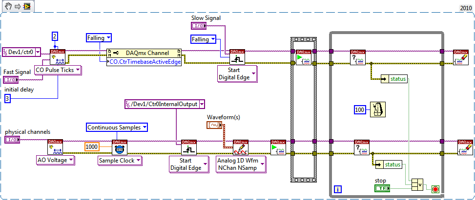
I want to create a trigger depends on two signals incoming (from external function generators) of PFI. Both are square waves, but the frequency is different. My wish is to trigger the slower from the top down as three top to bottom the faster and then generate an analog output. The picture is hopefully more descriptive than my words.
I use a NI DAQmx 6713 card. It doesn't matter if the solution is a LabVIEW VI or a C++ writes the text file. All the recommendations of good tutorials or similar is welcome. I managed to trig the arbitrary waveform after signal A or B, but I can't have the status of "County/wait three impulses."
Best regards
K. Berg
Hi K Berg,
It is possible with the 6713 - you will need to use a meter of output to generate the trigger for your AO signal. Use your signal slow to raise the output of the counter. Use the fast signal for the time base of the counter with an initial value 3 delay ticks. The meter goes off on the edge of your slow signal and once that was triggered will generate a pulse after 3 ticks of the fast signal.
Best regards
-
How do switch you between multiple channels to indicate which channel to acquire the data from?
I'm trying to builld a VI where I can have an option to enable or DISABLE multiple channels depending on the modules plugged into the chassis and then acquires the data of the channels which are turned on and where other acquisition parameters do not change. Is there any specific/switch where can I do this? Please answer as soon as possible. Its quite urgent. Thank you
You use DAQmx? To change the assignment of the data acquisition channels, you must close the currently open session and then create a new session with the new channel definition. So the order of execution:
Create task or virtual channel - read - clear task of triggering and synchronization of the configuration - set new channel list and to create a task - read - clear task, etc...
-
Select multiple channels for a single task - control and shift keys do not work
Hello
Following the advice of several other positions, I try to choose several physical channels in the drop-down list so that I can then use the function "unflatten channel channel" later. It seems that if I hold this key is pressed or cntrl, I should be able to select multiple channels in the list, however, this does not work for me. I tried to go in the "navigation key" property for the control channel to task, but there not all listed associations. Someone else has encountered this and found a solution? I previously around that by declaring several channels by a colon (for example, ai1:3), but it does not work for the unflatten function.
Thank you
Claire.
If I understand correctly, I think that you need to do is use a task property DAQmx. Try to use the channels property to get an array of strings.
-
Sampling of multiple channels on the same frequency
I have some problems to understand how to configure my cDAQ chassis. I have a work labview program that should (I guess it doesn't!) sample 5 channels at 5 Hz each channel. When I got the system data each analog channel (all in the same spot) resembles a ~1.xx Hz sampling.
I created my task to taste 3 analogue to 5 Hz, 1 sample per channel. It gives me a sample rate effectiveness of sample of 1,666 Hz per channel? That's what seem to tell me my data.
If the above is true, change my task to make a sample 3 channels at 15 Hz, 1 sample per channel will give me a sampling rate of efficiency of 5 Hz per channel?
The other 2 channels are digital and on another task and appear to be working (fingers crossed!)
Thank you and happy holidays.
Kyle
I can post code if this confusing issue.
-
Synchronization of the inputs and outputs with different sampling frequencies
I'm relatively new to LabView. I have a NOR-myDAQ, and I am trying to accomplish the following:
Square wave output 10 kHz, duty cycle 50%.
Input sampling frequency of 200 kHz, synchronized with the output that I get 20 analog input samples by square wave, and I know what samples align with the high and low output of my square wave.
So far, I used a counter to create the square wave of 10 kHz, display on a digital output line. I tried to pull the document according to (http://www.ni.com/white-paper/4322/en), but I'm not sure how sample at a different rate than my clock pulse. It seems that this example is intended rather to taste one entry by analog clock pulse. There may be a way to create a faster clock (200 kHz) in the software and use that to synchronize the analog input collection as well as a slower 10 kHz output generation square wave?
I eventually have to use the analog inputs to obtain data and an analog output to write the data channel, so I need the impetus of the square wave at the exit on a digital PIN.
How could anyone do this in LabView?
Hi Eric,.
All subsystems (, AO, CTR) derive from the STC3 clocks so they don't drift, but in order to align your sample clock HAVE with pulse train that you generate on the counter, you'll want to trigger a task out of the other. I would like to start by a few examples taken from the example Finder > Input and Output material > DAQmx. You can trigger GOT off the train of impulses, start by Gen digital Pulse Train-keep -you probably already use a VI like this to generate 10 k pulse train. AI, start with an example like Acq Cont & chart voltage-Ext Clk - Dig Start.vi-you'll want to use the internal clock so just remove the control of the "Source of the clock" and it uses the internal clock. From there, simply set the "Source of the command" either be the PFI line generates the meter, or ' /
/Ctr0InternalOutput '-assuming that you are using the counter 0. You'll want to make sure that the start of the task HAVE faced the task of counter I is ready to trigger off the first impulse. They should be aligned at this point. For debugging, you can use DAQmx export Signal to export the sample clock - you can then brought the train line and the PFI pulse to make sure that they are aligned.
Hope this helps,
Andrew S
Maybe you are looking for
-
I updated my iPhone 6 the last iOS 10.0.1 and now I'm locked out access to my limitations in settings > general > Restrictions. Yes, I know that my password, but when I enter my password I get the message "Failed password attempts", to try again in 1
-
What Linux on Toshiba Satellite L300D-10 has
Hi all. I have this notebook "Toshiba Satellite L300D-10 a" and I can't install any distro linux on it. Recently I have updated the BIOS to version 1.50 and now I am able to install Debian and PCLinuxOS, but again, they do not work as they should wor
-
My office is an imac, and I have two laptops one computers running on windows xp, the other on windows 7 starter edition. I shared the printer on my network and my laptop than rusn on windows 7 can print without problem. When I try to print from the
-
When a software completed the trail period then its can not be opened. How do I activate this kind of app without installing windows?
-
Safe icon Downloads: suggestions on safe sites for this?
As a freelance writer, I change desktop standard icons (photo looking for standard folder) for colorful images, often a link with the content of the file, to help me stay organized. However, I'm always afraid to download 'free' icon files that are