Temperature control MLC9000 + 250 West by Ethernet/IP
Could someone help me?
I'm doing the Ethernet/IP protocol for temperature control West model MLC9000 + BM250 S160 AE
I have a software MLC 9000 + workshop, but I can not find information or documents on this subject.
The best and considers
Kelbert
Hello
Got a link you send me on Ethernet/IP in LabVIEW.
I tried 2 ways:
A fo I tried with a llb modbus ethernet, but I guess the problem I know not which is the starting address, I need to put out I have no documentation or imformation from the controller I have here.
I tried with another one set up server modbus I/O, but there are a few probleml.
Check out the accessories to add.
Best regards
Kelbert
Tags: NI Hardware
Similar Questions
-
without using DAQ how a PID controller for temperature control
Mr President.
IAM trying to make a PID controller for temperature control in labview. But I have no devices data acquisition. Then without using DAQ how a PID controller.please suggest some useful block diagram.plz give me an answer. I tried one, but not working.below attached is my work.
as a learning exercise, some devices can be simulated in the Explorer to measure (performance measure explore, right click on devices, select Create new.) Select simulated device and choose your device, you can search by product code for example 4070 for a dmm)
I hope this helps you begin to learn labview, depending on how advanced you can I strongly suggest looking in training of core 2 and core 1 but also by looking at the examples that come with labview
-
guidance inertia temperature control
Dear people,
I would ask for advice from experienced people in control theory.
Recently, I'm working on a very interesting device, it is called inertial guidance vacuum calorimeter (there is a type of isothermal calorimeter). I'm doing a new LabView program for this camera, and I try to increase its stability/accuracy as much as I can. This calorimeter can measure heat sample level micro-watt powers. The principle of measurement is the following (see attached diagram):
We want to measure the heat flowing from the outside door-sample, this is done via Peltier (thermoelectric sensor) sensor. To obtain valid data, temperature must be very precisely constant everywhere in the calorimeter (isothermal method). The inner parts of the calorimeter thermally protected against ambient temperature with blank shields and high radiation. Double room empty closed circulates water through a heat exchanger, the heat reservoir.
For thermal stability, there are 3 loops controlled:
1 control loop. : this controls using PID, (method of classic platinum resistance 4W) constant water temperature
2 control loop. : this is the first step to stabilize the temperature of the inner part, PID loop classic platinum resistance and drives a pump to Peltier heat between the support and the "base". This can achieve only a constancy of temperature around 0.1 mK.
3 control loop. : when the ultimate stability is reached with the control loop 2, it is off, and his conduct of the current production constant value. Now the loop3 begins, and that's the tricky part: there is a cylindrical copper heavy 'inertial mass' with high calorific value (much higher then the base) standing on the base. Because it has a high calorific, even temperature fluctuations very tiny in the performance of temperature-controlled database a measurable voltage in the thermoelectric sensor between inertial mass and the base. This value is measured by the meter nanovoltage (Keithley). So I use this value to control the heat under the base pumps. In principle, if there is no heat flowing between inertial mass and the base, we are in thermal equilibrium.
With this concept, it is possible the stability of temperature range well below nanokelvins!
Recently, I play with the control settings, but only using simple PID controls (I have the PID toolkit). The method explained above is a kind of analogy of inertial guidance in mechanical control. I wonder if someone could give me advice or direction how I could further improve the stability of this control. Perhaps some more advanced control system? Feed-forward?
Thank you very much for the advice,
Kind regards
If I follow correctly, the feedback control loop 3 is measured using the Keithley via GPIB. And these readings take approximately 0.6 seconds. The control loop cannot work faster than the measurement system (unless you want a lot more unstable!). Most high precision instruments offer a compromise between resolution and speed. I took a look at the profile of 2182 and it seems you may have need of any resolution, so accelerate may not be an option.
The approach of bottle neck is probably a good with all that you have done so far. It will help you to avoid putting too much time into something that won't make much improvement.
Another thought: how noisy/drifty are power supplies/amplifiers driving Peltier devices? I worked on a system several years ago, where the objective was stability uK ~ 10 and noise and drift in the power circuits were the main limitations. Most of the engineers designing such devices never think of parts per million or fractions. Especially with the slow return of nanovoltmeter, drift or noise in the power circuts could be important. Also look at how the constant output mode that the external loops are open loop constantly.
Lynn
-
Relay using the temperature control
Is there a code example using a TC 120 to control PS RLY 420 FP? I am trying to enable / disable a device by using the temperature.
The first problem with your VI, is that it is not executable for several reasons. For most various terminals that must be wired which are not. Click on the broken arrow of race and it will show you these errors.
I don't think you want to put your Fieldpoint writing in a housing structure. You should wire the Boolean Fieldpoint write directly. A true value turns on the relay, a fake he died.
Another thing that I see in your VI, it is that there is not the channels defined in the Fieldpoint i/o constants.
-
updated duty cycle in PWM/PID temperature control
Hi fellow users of Labview,.
I control the temperature in a box by reading the temperature (voltage) of a PT100 element and output pulses PWM with PCI 6221 counter to close the circuit of a relay to solid state to power my heating unit.
Using PID (not quite yet set in the code below), I expect the cycle also adapt according to the proximity we are at the point (i.e. it would be pulse refine put it to not be 50% when sound near the set point, but rather be like 10% so it is not exceeded). Right now my code does nothing at the time when the process variable exceeds the set value (I have the operating factor set to 1E-5 in this case, mainly off the coast, because if I don't do this, the counter always pulse outputs...)
How to integrate the update of the PWM pulses in my code?
Thank you!
HessenMob
I think I solved the problem.
As a new person on these forums, I didn't know how to remove my post...
An updated version is attached below!
Any thoughts on how to tune the K_p, K_i, K_d settings?
Thank you
HessenMob
-
Omega CN8202 temperature control Labview (Serial Port, RS-232 Communication) Question
I'm a fidling perfect starting with Labview, as I just started with it today, so sorry if these questions are obvious.
I will work with an Omega CN8202 thermostat. As indicated in the title of the topic, one used uses serial communication and RS-232 Protocol. However, the LabVIEW version is 2007, so I don't think that all the drivers here would work
Only, I want to be able to set a temperature on the CN8202 of a computer and no need to do something about the ramp or soak time. How could I change the drivers so that they would work in the 2007 version of LabVIEW?
There is no such thing as LabVIEW 2007. The current version is displayed when you launch or open the About window. If it is really longer than 8.0, then the version conversion Commission. Link is at the top of the page on the set of LabVIEW.
-
PID tuning - temperature control
Hello
I'm working on a project of PID control with a dreaded heating control. The radiator is small enough ~ 10 watts, so the response time is very fast. My set point increases, my HP decreases. I'm controlling the radiator with a continuous feed, so the nominal value is an environment of tension and I left PID +/-100% 0 voltage swing at full scale.
The Kc is of about 0.4.
With a control P, Kp = 0.2, I get a damped oscillation, which hovers at about 2-4% higher than the set value.
With IP control, Kp = 0.2, Ki = 0.00001, I get a constant oscillation around the setpoint.
An example with PI control is attached. It seems that my sample rate is too slow (the PV and SP are made with GPIB).

The sequence of events is--> order SP-> (wait)--> PV read--> PID use to set the new SP--> (loop)
I tried to improve it by putting the measure of PV in a parallel loop. This seems to help some, but does not eliminate the oscillation. Old time loop was ~ 0.3 seconds, now it is 0.15 seconds. Faster and my loop time< pv="" measurement="">
Any suggestions? I tried the Autotune PID vi, but he could never solve the system.
I've done a few things to improve the response:
1.), I use a PID of two floors. The "inner loop" PID control constantly power from 0 to full scale. The "outer loop" adjusts the power + / to reach the set point. (fine adjustment) Each PID loop has its own set of PID parameters.
(2.) for some reason, control PID never worked well because my point was inversely proportional to the power. I created a formula that has converted my set point to a function which is proportional to the power in watts.
-
Re: Room Temperature for Satellite A100-999
Hi all
I have a Toshiba Satellite A100-999 (old lil :/) with XP
I was wondering what are the temperature ranges at low, medium or high performance for the motherboard and CPU.
at the present time about the temperature I have are: (Celsius)
Motherboard: 60 + -.
CPU: 65 years and more-When it has a high performance, it reached 90 - 95 +-. And if im right... the CPU with this temperature control can be activated automatically right?
As im not an expert in the field, can someone guide me a bit?From now to detect temperatures im using the software: Everest AIDA64. (I guess that temperatures are not 100% Reliable, but they give me an idea).
If there are ways to cool the laptop (I know cleaning is one of them of course) I would be grateful to receive some information.Thanks in advance
concerning
> I was wondering what are the temperature ranges at low, medium or high performance for the motherboard and CPU.
It is not easy to say dude. The temperature can be always different and always depends on the use of the laptop.
On the Intel page, you will find details about your CPU and you can find the temperature for the CPU limit. It s mainly around 100 C.However, if the temperature is too high, then the laptop would shut down automatically to prevent the equipment from damage. If the laptop is secure with such protection.
By the way; the temperature can occur at a higher value if cooling modules and grids are obstructed by dust. So it s advisable to clean the grilles and fans of compressed air for usinf time spraying time.
-
How to read the laptop temperature
Hi all
I searched TOSHIBA software Assits for a temperature gauge where I can read the temperature inside the computer, but have not been able to find anything.Did I miss something? Or do I have to install a third party software for that? And if so, does anyone know any good?
Hello
To my knowledge, you will not find any tools of temperature control material on Toshiba laptops. As far as I know that this tool is not preinstalled.
So, if you want to use such tool, so you can use any 3rd party application.
But I m not 100% sure what tools effective and what not.I used the wonderful ;) advanced search option of this forum and found this topic:
http://forums.computers.Toshiba-Europe.com/forums/thread.jspa?threadID=14284It seems that the tool Hmonitor can properly read the temperature of the CPU.
Maybe you could test it. -
Hello world.
I wrote a program of temperature control in labview and used the PID Toolkit for it.
The entrance to the PID is the measured temperature and the output is a PWM signal fed to a relay that turns heater on or off.
The control works but I want the temperature to be stable within a range of + - 2%.
Currently, the temperature varies more than that.
IAM sure, this is the setting of the PID.
Because I have not worked with regulators PID Iam not exactly how to tune my system.
The best way I found is to zero I and D and make the system oscillate with P.
The only problem is that the system of temperature is so slow that it takes quite a long time to reach the set point which in turn would mean a lot of hours of tests only.
Now Iam just wondering if there is a faster way to set the PID controller?
Thanks in advance,
Best regards
Michael
I've used this method several times with slow heating appliances. It can take a long time to reach a stable temperature, but at least do not monitor constantly as he approaches this value.
In figure 3.4, Yes, the Min value is the initial value that is stable. It is OK to start an initial PWM output of 0, which speeds up the process, if your radiator is already at a steady temperature (the temperature in the room).
In general, the difference between the output of the first and the last values, better will be your control (you will get best results of going from 0 to more than 50% to 5%), but it will take more time to settle to a new value and of course you must ensure that you do not exceed the capabilities of your system. It's a good idea to have a separate alarm system in place that can cut power to heater if you exceed a temperature, especially if you plan to walk away from it until it stabilizes.
To a fixed cycle, the system will not continue to heat up indefinitely unless you have a perfect insulation without heat loss - but, as I mentioned above, do not choose a value that will not cause the system to overheat.
-
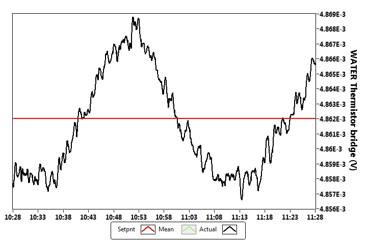
Hello
I have a loop of circulating water, and I control the temperature in the following way:
The sensor is a thermistor bridge, this bridge is driven with an accuracy of 5V reference (http://www.voltagestandard.com/New_Products.html). The output of this bridge is connected to a nanovoltmeter Keithley 2182. My LabView PID control (I bought the PID toolkit) drives a current source Keithley 2400 which is connected to a water - air heat exchanger Peltier solid state. On the side of this heat exchanger air is at a controlled temperature of the cabinet (air temperature stability is +-0.02 Celsius). The thermistor Bridge gives a signal of 50 mV/Kelvin to the excitement of 5V.
I have attached a photo where you can see measurement of a time data (sampling rate of 1 Hz). In general, I have a stability +-3rd-6 volt (standard deviation), which corresponds to the stability of Kelvin +-6-5.
I've set this PID command with the Ziegler-Nicholes tuning protocol standard, then first that I brought the stable oscillation system, and I measured the ultimate period time (1.375 minutes), and the nec plus ultra (147). The table Z - N gave to these values the following PID parameters:
P = 86.47
I have 0,687 min =
D = min 0,171
Overall, I am satisfied with my temperature control, but I'm looking for advice how to remove the visible oscillatory effect. This oscillation has a period of about 30-40 minutes, as you can see in the picture.
Is there something I could try to make my even more precise control? (it is also possible that I'm already at the possible gate given by the structural limits...)
Thank you very much!
Martins wrote:
Is there something I could try to make my even more precise control? (it is also possible that I'm already at the possible gate given by the structural limits...)
Can trace you to the output of the control loop (the value being written to the power source)? Specifically, draw out of the Keithley (if available), since the PID algorithm can output values with a finer resolution the Keithley can generate; Otherwise, around the PID output to match the resolution of the Keithley. See if the current alternates constantly between two specific output values, or if the output is continuously evolving during the swing.
What I think is happening, is that you have reached the limit of resolution of the power source, in this case, it will be difficult to eliminate this oscillation using PID, because the current source cannot output the exact value that you would allow to maintain the equilibrium temperature. If it does, the output changes between the two values from the nearest exit of you and you will always have a swing. You can try to increase the full gain (reduce integration time) to see if you can get a faster response and reduce the amplitude of the oscillation, but the trade-off is perhaps more great overtaking when you change the set value.
-
Hi all
I used to write small programs using Borland C++ Builder (very old) v3.0 control connected to the port, GPIB instruments. For this what should I include in my software is the "ni488.h" #include and bind "BorlandC_gpib - 32.obj".
Now, I want to be able to use the remote control of instruments via the ethernet port. From what I read, I think the port or the type of communication is called VXI. Ideally, I'm looking for a library to include in my projects, which is similar to ni488. If nothing is available for Borland C++ Builder v.3.0, then maybe for Borland C++ Builder 5.0 or 6.0? Or, if none is available, maybe a simple code for Visual Studio (Basic, C++, or c#) that allows me to send the command * IDN? and get the response of an instrument? I have NO Visa, IVI, and all the rest installed.
I know these days, there are a multitude of drivers written by the manufacturers, but I prefer to make my own mistakes in the treatment of channels instead of using 1 million complex functions

Kind regards
Nick
VXI - 11 is an Ethernet protocol that is supported by some providers of the instrument. If the device supports, and you are currently using VISA, that's all you need. To speak to a VXI-11 instrument controls are the same as if the instrument use a GPIB connection.
-
Connect the temperature and moisture to put in operation the fan
Guy! I need help on my connection how to connect the circuit?
The first that I want to connect is my data of thermistor. Then I connect the temperature control to turn on the fan. How to do?
Aloysius Low, student
For homework help, ask your classmates or your instructor.
BS
-
I'm working on a VI that uses different tab of monitoring the temperature controls. VI cycles in the tabs at predetermined times. I searched through the forums for a question like mine, and I've seen a few similar ones, but nothing which is exactly what I'm asking. I would like for the tab change color, change font style/size, or anything else every time that the display of the active tab. I wish that she be very obvious at a glance which tab is currently on. I've seen other posts where you can change the color of the tab, as well as its content, but I want only the tab itself to change, and that when it's highlighted. Is this possible to do? Thank you!
Altenbach says:
(there are probably better solutions, but which should you get).Here's a possible solution. Modify if needed.
-
Model: HP Pavilion dv6z-3000 CTO
Product no.: WG457AV
Age: years 3ish
So far measures: computer laptop cooling pad w / cleaned ventilation fan, Arctic Silver thermal paste, CPU undervolted
Environment: 90F
Problem: Overheating in about 20-30 minutes, drive hard cruises over the maximum temperature of operation posted by HP (35 ° C) and is close to its maximum temperature of use posted by its manufacturer (60 c).
The fan is not in its fastest mode with the CPU at 80 c / 70 c. I guess it saves it for 90 C +, but it's never there. The body is too hot to the touch (100F +), and I wouldn't hope children if she was used as a portable computer.
Things I know:
- CoolSense 2.0/2.1 + HP + current HP Support Assistant software framework lead the generic 'there is a problem with this Windows Installer package. A program run as part of the Setup did not finish as expected. Contact your personal provider or support package ".
- The software frame HP + HP Support Assistant v4/v5 listed for my laptop do not have included CoolSense block.
- SpeedFan and CPUCool cannot control the fan.
- The BIOS "fan always on" is lit. If the asset is cooling setting in Windows Power Plan.
- I tried to evaluate the DSDT table, but it seems to be formulated differently than the examples online and I can't find the speed of the fan.
- When I updated the BIOS to the latest version, the fan at full speed for the installation, so it can be controlled by the software.
- Without fan control the laptop is useless, because it fails at a random time. I can't perform long simulations or work effectively with him check every 30 minutes then cool for 10.
Give me something useful! I posted a few days ago and I got that ' when you bought it, was pre-installed CoolSense? Hell if I know, it was 3 + years ago!
I need a solution, he performs admirably in a temperature-controlled room! Why let a software controllable fan me to buy a new computer for 2 months, it must perform in 90F weather?
Since there has been no useful tips, I had to buy a new computer.
Therefore, it is a Lenovo.
It works, so more for her. You win that day, China.
Maybe you are looking for
-
I received 3 emails - "anti-spam feasibility" of Server Administrator - these are authentic or not?
Emails containing the following message is displayed: Your webmail Quota exceeded it's set/Quota limit which is 20 GB. You're running on 23 GB, due to hidden files and your mailbox from the folder. Please CLICK HERE to activate the anti-spam engine a
-
See the line between cursors on a graph
Hello I have a graph simple intensity with two sets of sliders on it, called 1 and 2 cursor cursor. I would like to make a distinction between the sliders so that when the user moves a cursor can see a line superimposed on the graph. Please see the
-
Dear Sirs, I have a problem, When I flashing WAG54G2 for the new firmware, I've been a power failure. Now my router does not work. Power LED and LED Internet is orange, DSL and wireless is GREEN. I try to connected by cable, link works, but not IP ad
-
Why always adobe must be installed after I install... Vist race im Internet 9
Whenever I log on a window pops up saying that adobe must be installed... I do and once more when I get back... he does again
-
Missing menu TIming calibration
Just bought CM1415fnw MFP. The manual says that you can change the frequency of calibration of the colors in printing quality > color calibration > calibration schedule. But the printer does NOT have this option, except the other two options: calib